www.ReadyLIFT.com - Phone: (877)759-9991 Installation Instructions 66-2215 7-11-16 MMC A NEW REPLACEMENT PART WILL BE SENT TO YOU IMMEDIATELY (877)759-9991 MON-FRI 7AM-5PM PST OR EMAIL: [email protected]WEBSITE: ReadyLIFT.COM **Please retain this document in your vehicle at all times** IF YOUR ReadyLIFT® PRODUCT IS MISSING A OR HAS A DAMAGED PART, PLEASE CONTACT CUSTOMER SERVICE DIRECTLY. For war- ranty issues please return to the place of installation and contact ReadyLIFT® . Limited Lifetime Warranty This unique product warranty proves our commitment to the quality and reliability of every product that ReadyLIFT® manufactures. The ReadyLIFT® product warranty only extends to the original pur- chaser of any ReadyLIFT® product, if it breaks, we will give you a new part. Warranty does not apply to discontinued parts. Our Limited Lifetime Warranty excludes the following ReadyLIFT® items; bushings, bump stops, ball joints, tie rod ends, heim joints and shock absorbers. These parts are subject to wear and are not considered defective when worn. They are warranted for 12 months from the date of purchase for defects in workmanship. This product warranty is voided if the vehicle is not aligned after kit installation and proper maintenance is routinely done. Product purchased directly from ReadyLIFT® has a 30 day return policy on uninstalled products from the date of purchase. Uninstalled product returns must be in the original ReadyLIFT® packaging. Please call (877)759-9991 to get an RGA# for any return. Customer is responsible for shipping costs back to ReadyLIFT®. Returns without RGA# will be refused. Contact ReadyLIFT® directly about any potentially defective parts prior to removal from vehicle. If the part in question is deemed warrantable an RGA# will be assigned and can be returned for repair or replacement. Replacement parts required prior to warranty claim completion must be purchased. Upon receipt and verification of deemed warranty parts claim, a credit or refund can then be processed to complete warranty claim transaction. ReadyLIFT® products are NOT intended for off-road abuse. Any damage or failure as a result from off-road abuse voids the warranty of the ReadyLIFT® product. ReadyLIFT® is NOT responsible for any subsequent damages to any related vehicle parts due to misuse, abuse, improper installation, or lack of maintenance. Fur- thermore, ReadyLIFT® reserves the right to change, modify or cancel this warranty without prior notice.
Transcript
www.ReadyLIFT.com - Phone: (877)759-9991
Installation Instructions 66-2215
7-11-16 MMC
A NEW REPLACEMENT PART WILL BE SENT TO YOU IMMEDIATELY
WEBSITE: ReadyLIFT.COM **Please retain this document in your vehicle at all times**
IF YOUR ReadyLIFT® PRODUCT IS MISSING A OR HAS A DAMAGED PART, PLEASE CONTACT CUSTOMER SERVICE DIRECTLY. For war-ranty issues please return to the place of installation and contact
ReadyLIFT® .
Limited Lifetime Warranty
This unique product warranty proves our commitment to the quality and reliability of every product that ReadyLIFT® manufactures. The ReadyLIFT® product warranty only extends to the original pur-chaser of any ReadyLIFT® product, if it breaks, we will give you a new part. Warranty does not apply to discontinued parts. Our Limited Lifetime Warranty excludes the following ReadyLIFT® items; bushings, bump stops, ball joints, tie rod ends, heim joints and shock absorbers. These parts are subject to wear and are not considered defective when worn. They are warranted for 12 months from the date of purchase for defects in workmanship. This product warranty is voided if the vehicle is not aligned after kit installation and proper maintenance is routinely done.
Product purchased directly from ReadyLIFT® has a 30 day return policy on uninstalled products from the date of purchase. Uninstalled product returns must be in the original ReadyLIFT® packaging. Please call (877)759-9991 to get an RGA# for any return. Customer is responsible for shipping costs back to ReadyLIFT®. Returns without RGA# will be refused. Contact ReadyLIFT® directly about any potentially defective parts prior to removal from vehicle. If the part in question is deemed warrantable an RGA# will be assigned and can be returned for repair or replacement. Replacement parts required prior to warranty claim completion must be purchased. Upon receipt and verification of deemed warranty parts claim, a credit or refund can then be processed to complete warranty claim transaction.
ReadyLIFT® products are NOT intended for off-road abuse. Any damage or failure as a result from off-road abuse voids the warranty of the ReadyLIFT® product. ReadyLIFT® is NOT responsible for any subsequent damages to any related vehicle parts due to misuse, abuse, improper installation, or lack of maintenance. Fur-thermore, ReadyLIFT® reserves the right to change, modify or cancel this warranty without prior notice.
www.ReadyLIFT.com - Phone: (877)759-9991
Installation Instructions 66-2215
2 7-11-16 MMC
Please read Instructions thoroughly and completely before beginning installation. Installation by a certified mechanic is recommended.
ReadyLIFT® Suspension is NOT responsible for any damage or failure resulting from improper installation.
Safety Warning: Suspension systems or components that enhance the on and off-road per-formance of your vehicle may cause it to handle differently than it did from the factory. Ex-treme care must be used to prevent loss of control or vehicle rollover during abrupt maneuvers. Always operate your vehicle at reduced speeds to ensure your ability to control your vehicle under all driving conditions. Failure to drive safely may result in serious injury or death to driver and passengers. Driver and passengers must ALWAYS wear your seat belts, avoid quick sharp turns and other sudden maneuvers. ReadyLIFT® Suspension does not recommend the combined use of suspension lifts, body lifts, or other lifting devices. You should never operate your vehicle under the influence of alcohol or drugs. Constant maintenance is required to keep your vehicle safe. Thoroughly inspect your vehicle before and after every off-road use. It is the responsibility of the retailer and/or the installer to review all state and local laws, with the end user of this product, related to bumper height laws and the lifting of their vehicle before the purchase and installation of any ReadyLIFT® products. It is the responsibility of the driver/s to check their surrounding area for obstructions, people, and animals before moving the vehicle. All raised vehicles have increased blind spots and damage, injury and/or death can occur if these instructions are not followed.
This suspension system was developed using a 295 - 65 R20 tire with 20” x 9” wheel and a offset of +25. If wider tires are used, offset wheels may be necessary and trimming may be required. Factory wheels can be used but are not recommended with tires over 11” wide. The stock spare rim can be run in an emergency. Please note that if running the spare factory tire, it is done for short distances and a speed not to exceed 45mph or damage to differentials may oc-cur.
www.ReadyLIFT.com - Phone: (877)759-9991
Installation Instructions 66-2215
3 7-11-16 MMC
BILL OF MATERIALS
Safety Warning Before you start installation: ReadyLIFT® Suspension highly recommends that the installation of this product be performed by a professional mechanic with experience working on and installing suspension products. Professional knowledge and skill will typically yield the best installation results. If you need an installer in your area, please contact ReadyLIFT® Suspension customer service to find one of our “Pro-Grade” Dealers. Notes:
Installation by a professional mechanic is highly recommended.
A Factory Service Manual for your specific Year / Make / Model is highly recommended for reference during installa-tion.
Vehicles with a two piece rear driveline may require a carrier bearing drop support bracket, call technical assistance fordetails.
All lifted vehicles may require additional driveline modifications and or balancing.
A four wheel vehicle alignment will need to be performed after installation of this product.
Speedometer / Computer recalibration is required if changing +/- 10% from factory tire diameter.
Use of a Vehicle Hoist will greatly reduce installation time.
Vehicle must be in excellent operating condition. Repair or replace any and all worn or damaged components prior toinstallation.
Description Qty
Aluminum Lift Spacers 2
M10 Flange Nuts 6
www.ReadyLIFT.com - Phone: (877)759-9991
Installation Instructions 66-2215
4 7-11-16 MMC
Park vehicle on a clean flat surface and block the rear wheels for safety. Engage the parking brake.
Record the stock vehicle measurements on both the front and the rear, this will provide a guideline on vehicle rake and lift height.
Measure from the center of the wheel up to the bottom edge of the fender well opening and record on the chart provided on page 2.
Disconnect the vehicle power source at the ground terminal on the battery.
Lock the steering wheel in the straight forward position with the col-umn lock or steering wheel locking device.
Raise the front of the vehicle and support with jack stands at each frame rail behind the lower control arms.
***2011 and newer models equipped with EPAS (Electronic Power Assist Steering), disconnect the power steering control module to avoid arching of the contacts in the internal power relay from a ham-mer blow or impact wrench.***
Raise the front of the vehicle and support with jack stands at each frame rail behind the lower control arms.
Remove the front wheels. (Fig 1)
Disconnect the ABS connectors in the engine compartment. Driver side is by the air box and the passenger side is next to the battery. (Fig 2, 3)
Remove the brake line brackets and ABS wires from the knuckle and frame. Make sure to hang ABS wire out of the way in a safe location so as not to damage the wire when removing the strut. (Fig 4, 5)
Disconnect vacuum line from the vacuum actuator. (Fig 6)
FIG 1
FIG 2
FIG 3
FIG 4
FIG 5
FIG 6
www.ReadyLIFT.com - Phone: (877)759-9991
Installation Instructions 66-2215
5 7-11-16 MMC
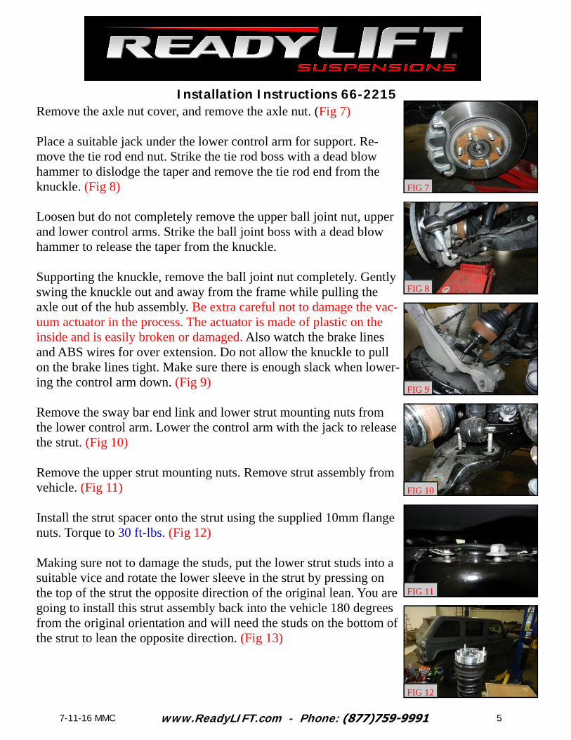
Remove the axle nut cover, and remove the axle nut. (Fig 7)
Place a suitable jack under the lower control arm for support. Re-move the tie rod end nut. Strike the tie rod boss with a dead blow hammer to dislodge the taper and remove the tie rod end from the knuckle. (Fig 8)
Loosen but do not completely remove the upper ball joint nut, upper and lower control arms. Strike the ball joint boss with a dead blow hammer to release the taper from the knuckle.
Supporting the knuckle, remove the ball joint nut completely. Gently swing the knuckle out and away from the frame while pulling the axle out of the hub assembly. Be extra careful not to damage the vac-uum actuator in the process. The actuator is made of plastic on the inside and is easily broken or damaged. Also watch the brake lines and ABS wires for over extension. Do not allow the knuckle to pull on the brake lines tight. Make sure there is enough slack when lower-ing the control arm down. (Fig 9)
Remove the sway bar end link and lower strut mounting nuts from the lower control arm. Lower the control arm with the jack to release the strut. (Fig 10)
Remove the upper strut mounting nuts. Remove strut assembly from vehicle. (Fig 11)
Install the strut spacer onto the strut using the supplied 10mm flange nuts. Torque to 30 ft-lbs. (Fig 12)
Making sure not to damage the studs, put the lower strut studs into a suitable vice and rotate the lower sleeve in the strut by pressing on the top of the strut the opposite direction of the original lean. You are going to install this strut assembly back into the vehicle 180 degrees from the original orientation and will need the studs on the bottom of the strut to lean the opposite direction. (Fig 13)
FIG 10
FIG 7
FIG 8
FIG 9
FIG 12
FIG 11
www.ReadyLIFT.com - Phone: (877)759-9991
Installation Instructions 66-2215
6 7-11-16 MMC
Though this step is not necessary, to ease reassembly to lower control arm, clamp the lower mounting pin in a suitable vice and remove the studs from the pin. Strike the end of the stud with a dead blow ham-mer until removed from the pin. Take care not to damage the threads. (Fig 14)
Rotate the strut 180 degrees from the factory orientation and install the strut with the offset studs to outside of the vehicle as stamped onto the spacer using the factory hardware. Do not tighten at this time.
Raise the lower control arm assembly to the strut and install the lower pins into the control arm. You will have to use the factory nuts to “press” studs back into the pin. Tighten the nuts until the stud is seated completely into the pin. Once seated, loosen again so the nuts can be properly torqued. If you have not removed the studs in the previous step, it will take some effort to line everything up but it will go together. Install the lower strut mount and sway bar end link to the lower control arm using factory hardware. Torque lower strut mount to 110 ft-lbs. Torque the sway bar end link to 40 ft-lbs.
Using the jack, raise the control arm and knuckle up towards the up-per ball joint while lining the axle up through the hub assembly being careful not to damage the vacuum actuator. Continue to raise the lower control arm until the upper control arm can be attached to the knuckle using the factory hardware. Do not tighten at this time. (Fig 15, 16)
***Very important*** To avoid damage to the vacuum actuator, these steps must done with major caution. Hold the axle and rotate the hub assembly while pulling outwards on the axle to engage the splines in the actuator to the splines on the axle. Once the splines are engaged, the axle will “pop” through the hub assembly. When the axle is seated you will be able to see the shoulder of the axle through the hub. If this shoulder is not visible, keep rotating the hub until it is. The shoulder will be 2mm under the mounting surface of the nut in the hub when properly seated. Install the axle using the factory hardware. Torque to 20 ft-lbs. (Fig 17, 18)
FIG 13
FIG 14
FIG 15
FIG 16
FIG 17
FIG 18
www.ReadyLIFT.com - Phone: (877)759-9991
Installation Instructions 66-2215
7 7-11-16 MMC
***Final install and checks***
Recheck that all hardware is of proper torque values and all electrical connections are hooked up. Start vehicle and verify that all dash warning lights are off. Cycle the steering wheel from lock to lock to check for any interference of steering intermediate shaft, steering extension, steering u-joint. wheels, tires, brake lines, hoses, wires, ect and ensure adequate clearance through out the suspension cycle. Adjust as necessary.
Install all warning tags and decals as directed: 1. Rear view mirror hanging warning card: Hang from rear view mirror to warn driver of vehi-
cle modification.2. Lifted truck warning decal: Apply decal to the upper left hand corner of the inside of the
windshield facing the driver.
Give all installation instructions, warranty information, and all remaining literature to the end user to keep with vehicle records.
Torque the upper ball joint nut to 85 ft-lbs.
Tighten the upper strut mounting hardware. Torque to 30 ft-lbs.
Install the tie rod end to the knuckle using factory hardware. Torque to 85 ft-lbs.
Install all brake line brackets and ABS lines to the knuckle and frame using factory hardware. Torque to 5 ft-lbs.
Install the wheels and lower the vehicle to the ground. Torque the lug nuts to the manufactures specifications.
Jounce the front suspension to get the vehicle to settle to ride height. Torque the upper and lower control arm to 120 ft-lbs.
Have the alignment set to the provided specs on the last page by a reputable alignment shop.
www.ReadyLIFT.com - Phone: (877)759-9991
Installation Instructions 66-2215
8 7-11-16 MMC
Place your message here. F or maximum i mpact, use two or thr ee sentences.
Final Checks & Adjustments
Post Installation Warnings: Once the vehicle is lowered to the ground, check all parts which have rubber or urethane components to insure proper torque. Torque wheels to factory specs. Move vehicle backwards and forwards a short distance to allow suspension components to ad-just. Turn the front wheels completely left then right and verify adequate tire, wheel, brake line, and ABS wire clearance. Test and inspect steering, brake and suspension components for tightness and proper operation. Inspect brakes hoses and ABS lines for adequate slack at full extension.
***FAILURE TO PERFORM THE POST INSPECTION CHECKS MAY RESULT IN VEHI-CLE COMPONENT DAMAGE AND/OR PERSONAL INJURY OR DEATH TO THE
DRIVER AND/OR OTHERS***
Vehicle Handling Warning: Vehicles with larger tires and wheels will handle differently than stock vehicles. Take time to familiarize yourself with the handling of your vehicle.
Wheel Alignment/Headlamp Adjustment:
It is necessary to have a proper and professional wheel alignment performed by a certi-fied alignment technician. Align the vehicle to factory specifications. It is recommended that your vehicle alignment be checked after any off-road driving. In addition to your ve-hicle alignment, for your safety and others, it is necessary to check and adjust your vehi-cle headlamps for proper aim and alignment
Vehicle Re-Torque and Safety Inspection:
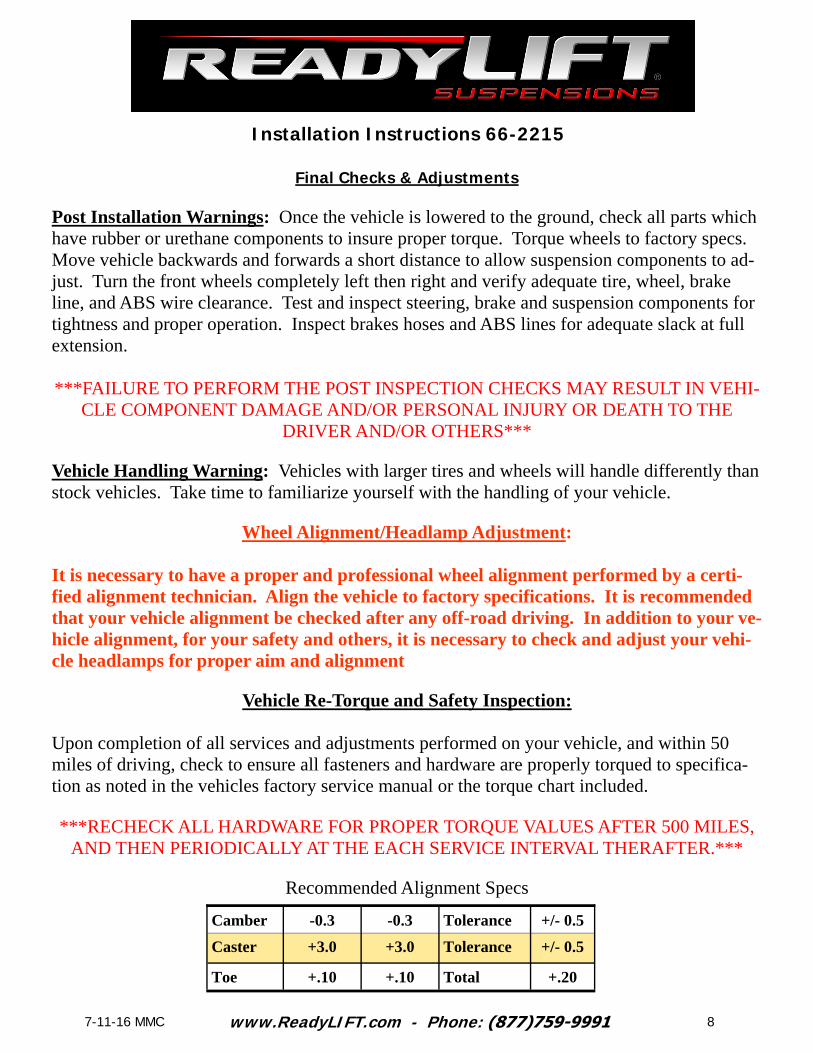
Upon completion of all services and adjustments performed on your vehicle, and within 50 miles of driving, check to ensure all fasteners and hardware are properly torqued to specifica-tion as noted in the vehicles factory service manual or the torque chart included.
***RECHECK ALL HARDWARE FOR PROPER TORQUE VALUES AFTER 500 MILES, AND THEN PERIODICALLY AT THE EACH SERVICE INTERVAL THERAFTER.***