BRACED EXCAVATION 68 BRACED EXCAVATION The following example concerns an excavation as indicated in Figure 68.1(a). The excavation is 15 m deep and 30 m wide. The geometry is such that symmetry considerations cannot be utilized. The excavation is performed in a sequence of stages and struts are inserted at regularly intervals to eventually reach the final configuration shown in Figure 68.1 (b). The medium and dense sands Medium sand Soft clay Dense sand 30 m +3 m -4 m -13 m -15 m 0 m -30 m 20 m +3 m 1.5 m To be excavated Existing wall (Rigid) 1.5 m 2 m 3 m +3 m +3 m 0 m -2 m -5 m -8 m -11 m -15 m -20 m (a) Initial (b) Final Figure 68.1: Initial (a) and final (b) configurations. 261
Transcript
BRACED EXCAVATION
68 BRACED EXCAVATION
The following example concerns an excavation as indicated in Figure 68.1 (a). The excavation is15 m deep and 30 m wide. The geometry is such that symmetry considerations cannot be utilized.The excavation is performed in a sequence of stages and struts are inserted at regularly intervalsto eventually reach the final configuration shown in Figure 68.1 (b). The medium and dense sands
Medium sand
Soft clay
Dense sand
30 m+3 m
-4 m
-13 m-15 m
0 m
-30 m
20 m+3 m
1.5 m
To be excavated
Existing wall (Rigid)
1.5 m
2 m
3 m
+3 m+3 m
0 m
-2 m
-5 m
-8 m
-11 m
-15 m
-20 m
(a) Initial
(b) Final
Figure 68.1: Initial (a) and final (b) configurations.
261
BRACED EXCAVATION
Figure 68.2: Soil materials.
are modelled as Mohr-Coulomb materials while the soft clay is modelled as a Tresca material. Theparameters of the three materials are shown in Figure 68.2. The sheet piles are modelled as Plateswhile the struts are modelled using the Connector elements. The parameters of these elements areshown in Figure 68.3. Upon installation, the struts may or may not be preloaded. In the followingboth possibilities are investigated and the response of the system for each strategy are compared.
Figure 68.3: Sheet piles (Plates) and struts (Connectors).
68.1 Without preloading
We first consider the case where the struts are not preloaded. The program is summarized in Table68.1. The first two stages (Stage 0 and 1) account for the initial stresses and the installation of thesheet piles respectively. The excavation then begins in intervals of 3 m, with a strut installed 1 m
262
BRACED EXCAVATION
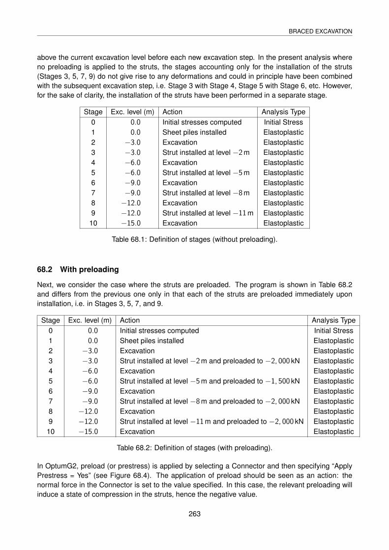
above the current excavation level before each new excavation step. In the present analysis whereno preloading is applied to the struts, the stages accounting only for the installation of the struts(Stages 3, 5, 7, 9) do not give rise to any deformations and could in principle have been combinedwith the subsequent excavation step, i.e. Stage 3 with Stage 4, Stage 5 with Stage 6, etc. However,for the sake of clarity, the installation of the struts have been performed in a separate stage.
Table 68.1: Definition of stages (without preloading).
68.2 With preloading
Next, we consider the case where the struts are preloaded. The program is shown in Table 68.2and differs from the previous one only in that each of the struts are preloaded immediately uponinstallation, i.e. in Stages 3, 5, 7, and 9.
Stage Exc. level (m) Action Analysis Type0 0.0 Initial stresses computed Initial Stress1 0.0 Sheet piles installed Elastoplastic2 −3.0 Excavation Elastoplastic3 −3.0 Strut installed at level −2m and preloaded to −2, 000 kN Elastoplastic4 −6.0 Excavation Elastoplastic5 −6.0 Strut installed at level −5m and preloaded to −1, 500 kN Elastoplastic6 −9.0 Excavation Elastoplastic7 −9.0 Strut installed at level −8m and preloaded to −2, 000 kN Elastoplastic8 −12.0 Excavation Elastoplastic9 −12.0 Strut installed at level −11m and preloaded to −2, 000 kN Elastoplastic
10 −15.0 Excavation Elastoplastic
Table 68.2: Definition of stages (with preloading).
In OptumG2, preload (or prestress) is applied by selecting a Connector and then specifying “ApplyPrestress = Yes” (see Figure 68.4). The application of preload should be seen as an action: thenormal force in the Connector is set to the value specified. In this case, the relevant preloading willinduce a state of compression in the struts, hence the negative value.
263
BRACED EXCAVATION
Prestress is applied via the property
window on the right by selecting the
Connector. Application of presstress
is indicated by a superposed on
the Connector.
Figure 68.4: Application of preload in Stage 7.
68.3 Results
68.3.1 Factor of safety analysis
Before deformations are determined, a Strength Reduction analysis is conducted for each stage.The results, shown in Figure 68.5, reveal that the factor of safety remains above 1.9 throughout theexcavation. It should be noted that preloading does not affect the factor of safety.
Excavation level (m)
1.5
2.0
2.5
3.0
3.5
4.0
4.5
5.0
Fa
cto
r o
f S
afe
ty
Initial state
Sheet piles
installed
Excavation to -3 m
Strut 1 installed
Exc. to -6 m
Strut 2 installed
Exc. to -12 m
Strut 3 installed
Strut 4 installed
Exc. to -15 m
Exc. to -9 m
0 3 6 9 12 15
Figure 68.5: Factor of safety versus excavation level.
264
BRACED EXCAVATION
68.3.2 Displacements
With a reasonable level of safety against failure verified, the next step is to determine deformationsaccording to the programs outlined in Tables 68.1-2.
The displacement fields at the final stage for the two cases – with and without preloading of thestruts – are shown in Figure 68.6.
2.5 cm
3.5 cm
7.3 cm
Without preloading
With preloading
Figure 68.6: Final configurations without (top) and with (bottom) preloading of struts.