Page 1
JAERI-Conf 96-010
6.8 EVALUATION OF LONG-TERM CREEP PROPERTIES OF HASTELLOY XR IN
SIMULATED HIGH-TEMPERATURE GAS-COOLED REACTOR HELIUM
Yuji KURATA, Yutaka OGAWA*. Tomio SUZUKI,
Masami SHINDO, Hajime NAKAJIMAand Tatsuo KONDO**
Japan Atomic Energy Research Institute.JAPAN
* now Research Institute for Metals, Tohoku University.JAPAN
** now Faculty of Engineering, Tohoku University.JAPAN
ABSTRACT
Creep properties are among the important basic items of material performance for
design of high temperature components of high-temperature gas-cooled
reactors(HTGRs). In order to evaluate creep properties of Hastelloy XR (a modified
version of the conventional Hastelloy X) developed for the High-Temperature
Engineering Test Reactor(HTTR), long-term creep tests were carried out in simulated
HTGR helium at 800, 900 and lOOO'C. The test results up to about 50,000h showed no
significant degradation in creep properties. The creep-rupture strength obtained through
the long-term tests was above the level corresponding to the design allowable creep-
rupture stress of the HTTR. Rupture lives could be estimated with sufficient accuracy
using Larson-Miller parameter. The values of the stress exponent were 4.5 to 5.7 when
the stress dependence of the steady-state creep rate was expressed in terms of the
Norton equation. It was judged that dominant creep process was dislocation creep. The
relationship between the steady-state creep rate and the rupture life was expressed in
terms of the Monkman-Grant equation. Carburization during creep in simulated HTGR
helium did not degrade creep properties of this alloy. Internally formed cavities and
cracks were initiated at sites of precipitates at grain boundaries, growing nearly
perpendicular to the stress axis. Creep fracture was caused by the nucleation, growth
and link-up of grain boundary cavities in long-term tests. Two phases, Cr-rich carbide
and Mo-rich carbide, co-exisred in specimens after long-term creep tests.
- 3 3 8 -
Page 2
JAERI-Conf 96-010
1. Introduction
The HTTR, which uses helium gas as the primary coolant, is currently under
construction as the first HTGR in Japan(1). Creep properties are among the important
basic items of material performance to be considered in high-temperature structural
design of the HTTR. Although pure helium gas is inert, the primary coolant helium,
which passes through the large mass of hot graphite core structure, cannot avoid
containing slight amount of impurity gases, i. e., H2, H2O, CO, CO2 and CH4. It is
considered that these impurities can. cause oxidation and carburization or
decarburization of heat-resistant alloys and possible effects upon creep properties are
suspected. For this reason many research works on creep tests in flowing helium
containing a small amount of impurities have been carried out. We have also conducted
creep tests in simulated HTGR helium with special care on impurity control in helium.
An intermediate heat exchanger(IHX) of the HTTR is being manufactured using
Hastelloy XR. High temperature components such as the IHX were designed using High-
Temperature Structural Design Code^2) and Design Allowable Limits^. At the time of
the design of the HTTR a lot of creep data were used to generate the Design Allowable
Limits for which the allowable stress for long-time service was determined through some
reasonable extent of extrapolation from the test data obtained up to that time. The
allowable stress up to 105 h was determined using data up to about 25,000 Ir3 ' .
Therefore, it is necessary to confirm whether the allowable stress is sufficiently marginal
or not when creep data in longer tests are obtained.
We reported that there was no significant difference between helium and air in
the creep rupture lives at 800 to lOOO'C up to about 10,000h and that the test results
showed no significant degradation in creep properties^4'5). Since a series of creep tests
for Hastelloy XR in simulated HTGR helium have been accomplished, all results
including creep data up to about 50,000 h are analyzed in this study in conjunction with
carburization behaviour, microstructure observation and mechanism estimation of creep
deformation and fracture.
339
Page 3
JAERI-Conf 96-010
2. Experimental procedure
2.1 Specimens
The material tested in this study is Hastelloy XR developed for high temperature
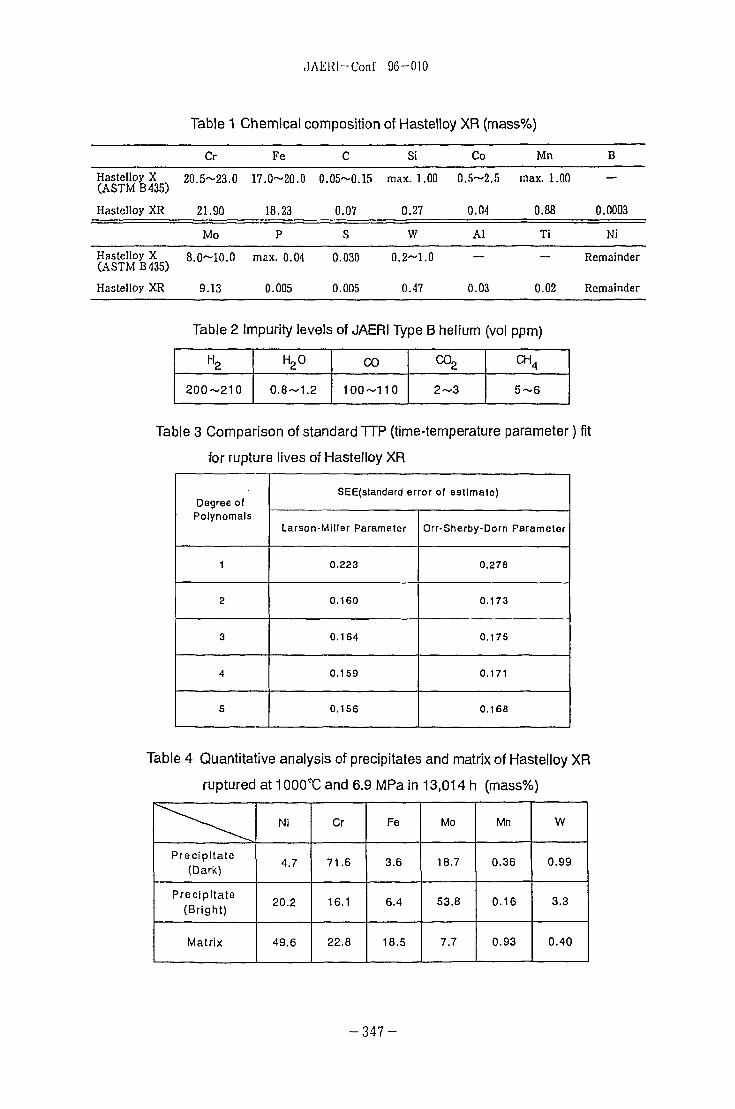
components of the HTTR. Hastelloy XR is an improved version of Hastelloy X. Table 1
shows the chemical composition of Hastelloy XR together with the specification of
Hastelloy X(ASTM B435). Hastelloy XR has a basal composition for the major
constituents common with that of Hastelloy X (i.e., nominally Ni-22Cr-18Fe-9Mo in mass
%), while contents of specific minor elements are optimized: Mn and Si are adjusted in
the optimum ranges and Al, Ti and Co are reduced to the possible lowest levels^. The
material was supplied in the form of bars of 15 mm in diameter. The solution treatment
temperature of the bars was 1180°C and the grain size was ASTM No.3-4. Specimens of
6 mm in diameter and 30 mm in gauge length were used for creep tests.
2.2 Test methods
Creep tests were carried out in helium environment designated as JAERI Type B
helium, which was one of the experimental specifications of the simulated HTGR
primary coolant environments. Impurity composition of JAERI Type B helium is shown in
Table 2. The chemical characteristic of this impure helium environment is low oxidizing
and slight carburizing for Hastelloy XR.
Single specimen type uniaxial creep machines'7' designed for a helium
environment were used. Special care was exercised in avoiding undesirable
perturbation of the local impurity composition at the test section due either to degassing
from or to reaction with the machine components.
Creep tests in the helium environment were carried out at 800,900 and lOOO'C,
and under 6.9 to 98.1 MPa. During the test, the temperature was monitored by platinum/
platinum-rhodium thermocouples attached along the specimen gauge section.
Microstructure observation was made for ruptured specimens using optical microscope ,
scanning electron microscope and EPMA.
- 3 4 0 -
Page 4
JAERI-Conf 96-010
3. Results and discussion
3.1 Creep rupture properties
Figure 1 shows the relationship between stress and time to rupture for Hastelloy
XR in JAERI Type B helium. The solid lines are the regression curves obtained from
analysis in terms of Larson-Miller parameter, and the broken lines the design allowable
creep-rupture stress (SR) of the Design Allowable Limits^. The design allowable creep
rupture stress was determined from the minimum creep rupture time which was one tenth
of the mean values obtained by applying the time-temperature parameter (TTP) method
to available creep rupture data in air and in simulated HTGR hel ium^. The strength
level of the creep-rupture data including results of creep tests up to 48,557.5h is above
SRat each test temperature, and the long-term data above 10,000 h show no significant
degradation in creep rupture lives.
The TTP method is often used to analyze creep-rupture data and to predict
rupture life and stress^8-9). In the present study, the following parameters were
investigated.
Larson-Miller: LMP=T(C+log tR ) , (1)
Orr-Sherby-Dorn: OSDP=log tR - Q/19.1425T, (2)
where tR is time to rupture, T the absolute temperature, and C and Q parameter
constants. Equation f(o), which represents stress dependence of TTP, is approximated
using polynomials of logarithmic of stress, a, as
f(a)=b0+b1log(a)+b2(log(o))2+- • •+bk(log(a))k, (3)
where bQ, b̂ ,b2, • • • , b^ are regression constants. Parameter constants in equations
(1)-(3) are optimized to minimize standard error of estimate (SEE) of log tR.
SEE=Jl(Yi-Yi)2/(nd-np-k-1), (4)
where Yi is a measured value of log tR, Yi an estimated value of log tR nd the number of
- 3 4 1 -
Page 5
JAERl-Conf 96-010
data points, np the number of parameter constant in TTP and k the degree of equation
(3). The optimization procedure was carried out following the study on standardization of
creep-rupture data evaluation of metals (9). Table 3 shows results of TTP analysis for
Hastelloy XR. It is found that the degree of polynomials is 2 for LMP and OSDP to have
good approximation. Furthermore, the application of LMP results in better fit than that of
OSDP since the SEE value of LMP is smaller than that of OSDP. On this basis, the
results obtained from analysis in terms of LMP are shown in Fig.1. These regression
curves fit experimental results containing long-term data. The final Larson-Miller
equation is shown as follows:
T(13.545293+logtR)
=23556.529+155.41729log(o)-1837.2623(log(a))2, (5)
The relationship between reduction of area and time to rupture at 800, 900 and
1000X: is shown in Fig.2. While rupture ductility generally decreases with increasing
rupture time, the results shown in Fig.2 have a tendency of leveling off in the decrease of
rupture ductility after a few thousand hours.
3.2 Creep curve and steady-state creep rate
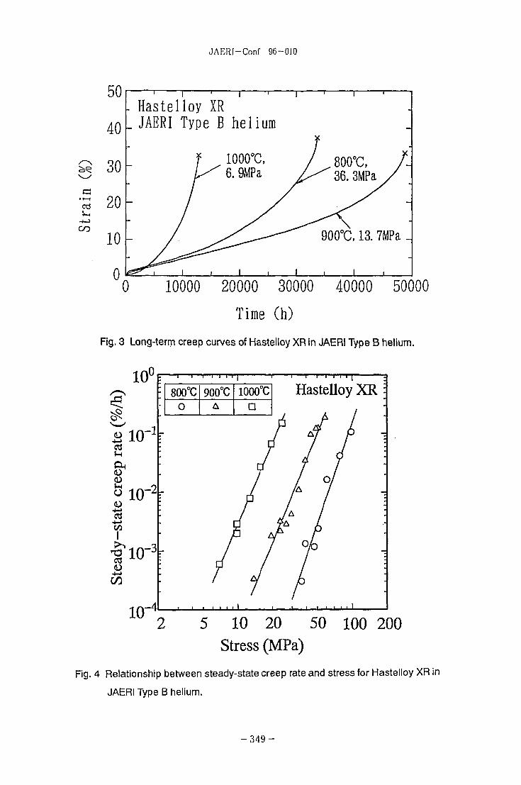
Creep curves in long-term tests are shown in Fig.3. It was reported that normal
type creep curves consisting of transient, steady-state and accelerated stages were
observed at 800^ and that, for Hastelloy XR at lOOOX), some irregular creep curves
were often observed ('™. In the present case, while long-term creep curves at 800 and
900^ are normal type curves as shown in Fig.3, the creep curve at 1000°C is the
irregular creep curve where the transient stage is hardly recognized. Figure 4 shows the
relationship between the steady-state creep rate and stress. The creep rate at 3% strain
was adopted as the steady-state creep rate when the steady-state region was not
recognized clearly in the irregular creep curves.
The relationship between the steady-state creep rate, ES, and stress, a, is
generally expressed as a power law, often called Norton's Law.
- 3 4 2 -
Page 6
JAERl-Conf 96-010
es = Ao n , (6)
where n is the stress exponent and A a constant. The stress exponent, n, obtained by
applying the least squares method to data at each temperature is 5.745 at 800T:, 4.686
at 900^ and 4.527 at lOOCC, respectively. The n value at each temperature does not
change within this experimental condition even if the stress decreases. It was reported
that n would be unity under the diffusional creep mechanism and that n would be greater
than 3 under the dislocation creep mechanism^'. The creep process of Hastelloy XR
within this experimental condition is interpreted to be dominated by the dislocation creep
mechanism since n values are above 3. Generally n value is about 5 for solution-
strengthened alloys, and it is often above 5 for precipitation-strengthened alloys^2 '.
Hastelloy XR is strengthened mainly by solution and additionally by precipitation. The
facts that the n value is above 5 at 800^) and that it decreases with increasing
temperature are explained by the decrease in the function of precipitation strengthening
due to the coarsening of precipitates at high temperatures.
An activation energy for creep, Qc can be derived from a plot of log eQ against
(1/T) at constant stress. The Qc values obtained were 340-450 kJ/mol. These values are
larger than the activation energy value, 285 kJ/mol'13', of lattice diffusion of Ni in Ni-20
at %Cr alloy. By these approaches, we can say that dislocation creep with n values of
about 5 and with Qc values larger than the activation energy for lattice diffusion of Ni in
Ni-20 at %Cr alloy is predominant under conditions applied in this study.
The following Monkman-Grant equation is useful to perform the prediction of life or
residual-life of high-temperature component.
log tR= c-mlog es , (7)
where c and m are constants. Figure 5 shows the relationship between the time to
rupture and the steady-state creep rate for Hastelloy XR. The regression curves at each
temperature or at all temperatures are also shown in this figure. Creep rupture lives for
Hastelloy XR can be predicted using the Monkman-Grant equation.
- 3 4 3 -
Page 7
JAERI-Conf 96-010
3.3 Carbon analysis and microstructure observation
Since decarburization and carburization have appreciable effects on creep
behaviour 0 4 - 1 5 ) , carbon analysis was carried out for ruptured specimens. Furthermore,
microstructure observation for surface and cross sections of ruptured specimens was
performed.
Figure 6 shows results of carbon analysis. Carbon content was analyzed for
section including rupture portion where there are many cracks and for 8-mm-diameter
section where there is little creep deformation. Carbon content in the former is high as
shown in Fig.6. This tendency becomes significant with higher temperatures and longer
times. On the other hand, there is only a little carburization in 8-mm-diameter section
even after long-term exposure to the impure helium. It can be pointed out that carbon
Intrusion during the steady-state creep stage was limited to a negligible level. No
specimen experienced decarburization which caused significant decrease in rupture
lives(14). Carburization during creep in simulated HTGR helium did not substantially
degrade creep properties of Hastelloy XR.
The following characteristic of microstructures of specimens ruptured in long-term
creep tests can be described from Fig. 7. The depth of the surface crack was about 100-
150 urn at 800 and 900^, and about 200 |xm at 1000°C. It was found that creep fracture
was caused by the growth and link-up of cavities nucleated at sites of precipitates at
grain boundaries, growing nearly perpendicular to the stress axis. Grain boundaries
perpendicular to the stress axis are under tensile stress. Precipitates at grain boundaries
under tensile stress coarsened as shown in Fig.7. In order to obtain information on
precipitates, EPMA analysis was carried out. Figure 8 shows the results of EPMA
analysis for the specimen ruptured at 900^ in 48,587.5 h. It is clear that bright
precipitates co-exist with dark precipitates in both secondary and backscattered electron
images. The bright precipitates have high molybdenum, silicon and comparatively low
chromium contents, while the dark precipitates have high chromium, carbon and
molybdenum, and low silicon contents. Table 4 shows quantitative analysis of
precipitates and matrix by EPMA. The dark phase is Cr-rich carbide presumed to be
- 3 4 4 -
Page 8
JAERI-Conf 96-010
2 3 g carb ide^ 6 ' " ' . The bright phase has high molybdenum and comparatively
low chromium contents. This bright phase enriched with Mo is presumed to be MgC type
carbide (1?).
4. Conclusions
Creep tests of Hastelloy XR were carried out in simulated HTGR helium up to
about 50,000 h at 800, 900 and 1000T:. The main results obtained are as follows:
(1)The test results up to about 50,000 h showed no significant degradation in creep
properties such as the rupture life, rupture ductility and the steady-state creep rate.
Creep-rupture stress is substantially above Spof the Design Allowable Limits.
(2)The stress dependence of the steady-state creep rate is expressed in terms of the
Norton equation. The values of the stress exponent is 4.5 to 5.7. On this basis, it is
judged that dominant creep process is dislocation creep.
(3) Rupture lives of Hastelloy XR can be estimated with sufficient accuracy using a
Larson-Miller parameter. The relationship between the steady-state creep rate and time
to rupture is expressed in terms of the Monkman-Grant equation.
(4)Some appreciable carburization was recognized in the specimens ruptured after
creep tests in simulated HTGR helium. Carburization during creep in the helium did not
substantially degrade creep properties of Hastelloy-XR.
(5)Creep fracture was caused by the growth and link-up of cavities nucleated at sites of
precipitates at grain boundaries, growing nearly perpendicular to the stress axis. There
were two phases, Cr-rich carbide presumed to be M23C6 and Mo-rich carbide presumed
to be MgC in specimens after long-term creep tests.
Acknowledgements
Authors are very grateful to staffs of Material Performance and Testing Laboratory
for their assistance during this long-term study.
- 3 4 5 -
Page 9
JAERI-Conf 96-010
References
(1)Japan Atomic Energy Research Institute : Present Status of HTGR Research and
Development (1996).
(2)HTTR Designing Laboratory, Department of Fuels and Materials Research and
Department of High-Temperature Engineering : JAERI-M 89-005 (1989) [in Japanese].
(3)HADA, K, MOTOKI, Y, and BABA, O,: JAERI-M 90-148(1990) [in Japanese].
(4)KURATA,Y, OGAWA, Y. and KONDO, T. :Nucl. Technol... 66, 250(1984).
(5)0GAWA, Y, KURATA, Y .SUZUKI, T., NAKAJIMA, H. and KONDO, T. : Nihon-
Genshiryoku-Gakkai Shi (J. At. Energy Soc. Japan), 36, 967 (1994) [in Japanese].
(6)SHINDO, M. and KONDO, T.: Proc. Conf. on Gas-Cooled Reactors Today, Bristol/UK,
1982(British Nuclear Energy Society) Vol.2, p.179.
(7)0GAWA,Y and KONDO, T.: JAERI-M 8801 (1980) [in Japanese],
(8)VISWANATHAN, R.: Damage Mechanism and Life Assessment of High-Temperature
Components, ASM International, Metals Park, Ohio, (1989).
(9)VAMAS Data Evaluation Committee : Study on Standardization of Creep-Rupture
Data Evaluation of Metals, The Iron and Steel Institute of Japan, (1994) [in Japanese].
(10)YOKOI, S., MONMA, Y, KONDO, T,., OGAWA, Y. and KURATA, Y : JAERI-M 83-138
(1983) [in Japanese].
(11)FROST, H.J. and ASHBY, M.F. : Deformation Mechanism Maps, Pergamon Press,
London, (1982).
(12)SIDEY, D. and WILSHIRE, B.: Met. Sci. J., 3, 56 (1969).
(13)MONMA, K., SUDO, H. and OIKAWA, H. : Nihon-Kinzoku-Gakkai Shi (J. Jpn. Inst.
Met.), 28, 188 (1964) [in Japanese].
(14)KURATA, Y, OGAWA, Y. and NAKAJIMA, H. : Tetsu-to-Hagane (J. Iron Steel Inst.
Jpn.), 74, 380 (1988) [in Japanese].
(15)idem.: ibid., 74, 2185 (1988) [in Japanese].
(16)SABOL, G.P. and STICKLER, R.: Phys. Stat. Sol., 35,11(1969).
(17)TANABE, T, ABE, R, SAKAI, Y and OKADA, M. : Transactions ISIJ (J. Iron Steel Inst.
Jpn.), 26, 968 (1986) .
- 3 4 6 -
Page 10
JAERl-Conf 96-010
Table 1 Chemical composition of Hastelloy XR (mass%)
Hastelloy X(ASTM B435)
Hastelloy XR
Hastelloy X(ASTM B 435)
Hastelloy XR
Cr
20.5~23.0
21.90
Mo
8.0~10.0
9.13
Fe
17.0~20.0
18.23
P
max. 0.04
0.005
C
0.05~0.15
0.07
S
0.030
0.005
Si
max. 1.00
0.27
W
0.2-1.0
0.47
Co
0.5~2.5
0.04
Al
0.03
Mn
max. 1.00
0.88
Ti
0.02
B
0.0003
Ni
Remainder
Remainder
Table 2
H2
200~210
Impurity
H2
0.8-
levels
0
'1.2
of JAERI
CO
100~11
Type
0
B helium
co2
2~3
(vol ppm)
CH4
5 ~ 6
Table 3 Comparison of standard TTP (time-temperature parameter) fit
for rupture lives of Hastelloy XR
Degree ofPolynomals
1
2
3
4
5
SEE(standard error of estimate)
Larson-Miller Parameter
0.223
0.160
0.164
0.159
0.156
Orr-Sherby-Dorn Parameter
0.278
0.173
0.175
0.171
0.168
Table 4 Quantitative analysis of precipitates and matrix of Hastelloy XR
ruptured at 10OO'C and 6.9 MPa in 13,014 h (rnass%)
Precipitate(Dark)
Precipitate(Bright)
Matrix
Ni
4.7
20.2
49.6
Cr
71.6
16.1
22.8
Fe
3.6
6.4
18.5
Mo
18.7
53.8
7.7
Mn
0.36
0.16
0.93
W
0.99
3.3
0.40
- 3 4 7 -
Page 11
JAKRI-Conf 90—010
GO
84CO
200
100
so
20
10
5
2
•
•
1 '., 800°C
*^"-.^—J1000°C
Regression curve "*"*
800°C0
900°CA
1000°C
n .
Hastelloy XR
s
1
10J 105102 103 104
Time to rupture (h)
Fig. 1 Stress vs. time to rupture for Hastelloy XR In JAERI Type B helium. The solid
lines are the regression curves obtained from application of Larson-Miller
parameter, and the broken lines the design allowable creep-rupture stress
(SR) of the Design Allowable Limits (3).
100
80
£ 60
oI 404—>
o
1? 20
' ' ' ' " I
. Hastelloy XR
0l1 I 1 1 1 III
• " I
800°C
O900°C
A
1000°C
D
D
o
Iff102 103 104
Time to rupture (h)
Fig. 2 Reduction of area vs. time to rupture for Hastelloy XR in JAERI Type B helium.
- 3 4 8 -
Page 12
JAERI-Conf 96-010
50
40
Q 30
Hastelloy XR_ JAERI Type B helium
900°C, 13. 7MPa _
0 10000 20000 30000 40000 50000
Time (h)
Fig. 3 Long-term creep curves of Hastelloy XR in JAERI Type B helium.
2 5 10 20 50 100 200Stress (MPa)
Fig. 4 Relationship between steady-state creep rate and stress for Hastelloy XR in
JAERI Type B helium.
- 3 4 9 -
Page 13
JAERI-Conf 96-010
3
B
105
104
103
102
101
io-
: ' ' ' ' ' ' " 1
r ^
- 800°C: 900°C
• iooo°c• All
: 800°C0
900°CA
,
1000°C
D
i •
Hastelloy XR \
-
10~3 10~2
Steady-state creep rate (%/h)
10o
Fig. 5 Relationship between time to rupture and steady-state creep rate (Monkman-
Grant relationship) for Hastelloy XR in JAERI Type B helium.
0.10
0.08
0.06& 0.10
COCO
I 0.08
I 0.06.coo
0.14
0.12
0.10
0.08
0.O6
2ZZ
1000'C
Open : section includingrupture portion
Solid : 8-mnrdiametersection
ZZZ As receivedr ) I t I I I i I
10' 102 103 10<
Time to rupture (h)
105
Fig. 6 Results of carbon analysis on the specimens of Hastelloy XR creep-ruptured in
JAERI Type B helium.
- 3 5 0 -
Page 14
JAERI-Conf 96-010
i- » . .V.: !i> -:"£',
x: x:o ioOJ 00IX) U)co" co"
23D.
0)
COQ.
co<6cocococu
COQ.
CO
toCOcu
oco"
2 oen a;.§ E
CO0.5enCD
COCU
w a>
P" P P§ § §co en °
UJ
CD
Q.CDCDi_O
ECD
i
cnc_o
CD
CO
CCX
o
COCO
X
§§
o ^.— CL
LL
- 3 5 1 -
Page 15
JAERI-Conf 96-010
•ocns
Pooen
"aCD
ZJ
a.CD(D
bCCX
(0X
ocoa>01
> NnJ coV m
X ooo ^
V-* r"
x: coO T-
co
- 3 5 2 -