322 Fermentation and Biochemical Engineering Handbook must also consider heating andor cooling requirements as well as to deliver the desired head pressure to overcome hydraulic pressure drop. Operating costs must also consider equipment maintenance, cost of cleaning chemicals and labor costs. CFF systems in general, have substan- tially lower maintenance and labor costs compared with other competing technologies. Cleaning chemical costs are typically low and account for only about 1 to 4% of the total operating costs.[3] 6.8 Safety and Environmental Considerations The proper and efficient operation of a cross-flow filtration system requires a design based on sound engineering principles and must rigorously adhere to safe engineering practices. CFF systems must be equipped with high pressure switches to safely diffise a high pressure situation and must also use materials and design criteria per American Society for Testing and Materials (ASTM) standards. Proper insulation is required in accordance with Occupational Safety andHealth Administration (OSHA) regulations for high surface temperatures or hot-spot when operating at elevated tempera- tures. For corrosive chemicals, proper handling and disposal procedures must be followed for operator safety. Containers approved by OSHA and other regulatory agencies must be used when transporting or transferring hazardous chemicals. In addition, proper procedures must be followedwhen mixing chemicals, either within the manufacturing process or while handling waste solutions. The majority of CFF processes are operated in a closed configuration which minimizes vapor emissions. Some traditional techniques such as centrifugal processes may generate aerosol foaming in the air (e.g., patho- gens) which is highly undesirable. 7.0 APPLICATIONS OVERVIEW Due to the highly proprietary nature of fermentation of biochemical products, the published descriptions on cross-flow filtrationperformance are very limited. This section will review some of the more important types of applications where cross-flow filtration is used. The performance descrip- tions are limited by available published information which is often incom- plete. As a result, at best, only qualitative or general comparisons can be made between the various technology alternatives.
Transcript
322 Fermentation and Biochemical Engineering Handbook
must also consider heating andor cooling requirements as well as to deliver the desired head pressure to overcome hydraulic pressure drop.
Operating costs must also consider equipment maintenance, cost of cleaning chemicals and labor costs. CFF systems in general, have substan- tially lower maintenance and labor costs compared with other competing technologies. Cleaning chemical costs are typically low and account for only about 1 to 4% of the total operating costs.[3]
6.8 Safety and Environmental Considerations
The proper and efficient operation of a cross-flow filtration system requires a design based on sound engineering principles and must rigorously adhere to safe engineering practices. CFF systems must be equipped with high pressure switches to safely diffise a high pressure situation and must also use materials and design criteria per American Society for Testing and Materials (ASTM) standards. Proper insulation is required in accordance with Occupational Safety andHealth Administration (OSHA) regulations for high surface temperatures or hot-spot when operating at elevated tempera- tures. For corrosive chemicals, proper handling and disposal procedures must be followed for operator safety.
Containers approved by OSHA and other regulatory agencies must be used when transporting or transferring hazardous chemicals. In addition, proper procedures must be followed when mixing chemicals, either within the manufacturing process or while handling waste solutions.
The majority of CFF processes are operated in a closed configuration which minimizes vapor emissions. Some traditional techniques such as centrifugal processes may generate aerosol foaming in the air (e.g., patho- gens) which is highly undesirable.
7.0 APPLICATIONS OVERVIEW
Due to the highly proprietary nature of fermentation of biochemical products, the published descriptions on cross-flow filtration performance are very limited. This section will review some of the more important types of applications where cross-flow filtration is used. The performance descrip- tions are limited by available published information which is often incom- plete. As a result, at best, only qualitative or general comparisons can be made between the various technology alternatives.
Cross-Flow Filtration 323
7.1 Clarification of Fermentation Broths
Fermentation broths tend to be very dilute and contain complex mixtures of inorganic or organic sub~tances . [~ l [~~] The recovery of a soluble product (MW range 500-2500 dalton) such as an antibiotic, organic acid or animal vaccine from fermentation broth takes several processing steps. The first step is the clarification of broth to separate the low molecular weight soluble product from microorganisms and other particulate matter such as cells, cell debris, husks, colloids and macromolecules from the broth me- d i~m. [~ ] [~*] In this step, microporous membrane filters (MWCO 10,000 to 500,000 dalton) compete with pre-coat vacuum filter or centrifuge.
When membrane filters are used, the soluble product is recovered in the permeate. This step is followed with diafiltration ofthe concentrate (continu- ous or batch) to improve yield. The permeate is then subjected to final concentration.
Many filtration processes operate in a batch configuration at or near ambient conditions (e.g., 20-30°C for penicillin) with some exceptions (e.g., 2-5OC for certain yeast fermentations and 8OoC for some higher alcohols).
Batch times can range from 12 to 22 hours depending on the desired final concentration and the required number of diafiltration volumes. At the end of a batch run, membranes are chemically cleaned. Cleaning may take up to 3 hours and involve the use ofan alkaline or acidic solution, or both, with a final sanitization step (e.g., 200 ppm NaOCI solution, a dilute solution of sodium bisulphite or a bactericide/fungicide). In some cases, steam steriliza- tion may be performed at the end of each run especially when using inorganic membrane filters.
Today many industrial fermentation broth clarifications are performed using cross-flow MF/UF membrane modules.[21[12] The advantage of CFF over traditional separation processes is not only in superior product flow rates but also in higher yields or lower product losses. Using diafiltration, up to 99% recovery can be 0btained.['*1[~~]
7.2 Purification and Concentration of Enzymes
Enzymes are proteins with molecular weights in the range of 20,000 to 200,000 dalton and are predominantly produced in small batch fermenters. UF often combined with diafiltration is widely used in the industry to produce a variety of enzymes such as trypsin, proteases, pectinases, penicillinase and carbohydrate^.[^]['^]
324 Fermentation and Biochemical Engineering Handbook
UF offers many advantages over traditional processes such as vacuum evaporation or vacuum evaporation with desalting. These include higher product purity and yields (concentration factor 10 to 50), lower operating costs, ability to fractionate when the molecular sizes of the components differ by a factor of at least 10. The availability of a wide range of MWCO membranes enables the selection of a suitable membrane to maximize flux without substantially compromising retention. UF can also minimize enzyme inactivation or denaturation by maintaining a constant pH and ionic strength. Other techniques such as solvent precipitation, crystallization or solvent extraction may sometimes denature the product owing to phase change.i8]
UF performance, however, may be influenced by process variables such as pH, nature of ions and ionic strength, temperature and shear. For example, Melling[sol has reported the effect of pH on the specific enzyme activity of E-coli penicillinase in the pH range 5 to 8 . Effects of shear inactivation associated with pumping effects are described by O’Sullivan et a1.[12] Recessed impeller centrifugal pumps or positive displacement pumps may be used to minimize enzyme inactivation due to shear.
7.3 Microfiltration for Removal of Microorganisms or Cell Debris
In recent years there has been a significant interest in the use of micro- organism-based fermentations for the production of many specialty chemicals. I5 11-[531
The product of interest may be produced by either an extracellular or intracellular process relative to the microorganisms. In either of these situations, one of the key steps is the efficient removal of microorganisms or cell debris from the fermentation b r ~ t h . [ ~ ~ ] [ ~ ~ ] In biotechnology terminology, this step, where cells are separated from the soluble components of the broth, is described as cell harvesting.
Filtration is often preferred over centrifugation due to problems associated with poor separation which results in either reduced product yield or purity. Aerosol generation during centrifugation could be a major problem. This can be alleviated in the CFF mode due to the closed nature of system operation. Additionally, centrifuges may require high energy inputs since there is no appreciable density difference between the bacterial cell walls and the surrounding medium. Pre-coat filtration, when applicable, will suffer from reduced product yield and lower filtration rates (e.g., 0.7 to 16 L/hr-m2).[52]
Cross-Flow Filtration 325
The processing steps differ depending on the location of the product relative to the microorganisms. For extracellular products, maximizing broth recovery by clarification is important since the product is in solution. When the product is located within the cell walls, concentration of cell mass is required followed by cell rupture and recovery of products from the cell debris.
Cross-flow microfilters, such as microporous hollow fiber or tubular, are preferred over plate and frame or spiral wound which are prone to plugging due to their thin channel geometry. In addition, CFF can be operated in the continuous mode with backwashing or backpulsing which has a beneficial effect on filtration performance. Process economics dictates the use of high cell concentration to maximize product yields but may hinder the recovery of soluble products (e.g., production of penicillin, cephalosporin). In other situations, high biomass concentrations may hinder the efficient removal (e.g., lactic acid, propionic acid) of inhibitory metabolites.[56] Similar situations exist in the production of acet~ne-butanol[~~] organic acids and amino acids from micro-organism-based fermentations
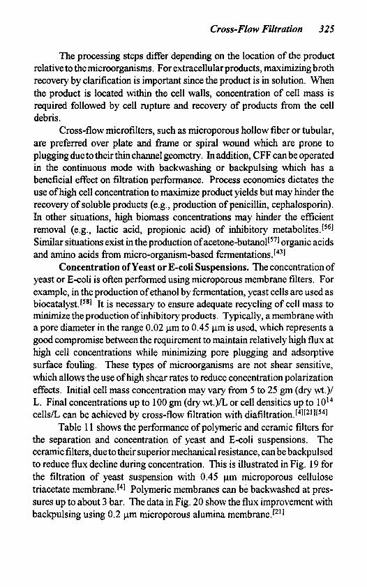
Concentration of Yeast or E-coli Suspensions. The concentration of yeast or E-coli is often performed using microporous membrane filters. For example, in the production of ethanol by fermentation, yeast cells are used as biocatalyst.[58] It is necessary to ensure adequate recycling of cell mass to minimize the production of inhibitory products. Typically, a membrane with a pore diameter in the range 0.02 pm to 0.45 pm is used, which represents a good compromise between the requirement to maintain relatively high flux at high cell concentrations while minimizing pore plugging and adsorptive surface fouling. These types of microorganisms are not shear sensitive, which allows the use of high shear rates to reduce concentration polarization effects. Initial cell mass concentration may vary from 5 to 25 gm (dry wt.)/ L. Final concentrations up to 100 gm (dry wt.)/L or cell densities up to IOl4
cells/L can be achieved by cross-flow filtration with diafiltrati0n.[~][~~1[~~] Table 11 shows the performance of polymeric and ceramic filters for
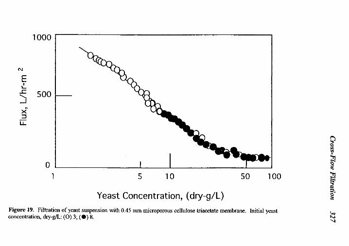
the separation and concentration of yeast and E-coli suspensions. The ceramic filters, due totheir superior mechanical resistance, can be backpulsed to reduce flux decline during concentration. This is illustrated in Fig. 19 for the filtration of yeast suspension with 0.45 pm microporous cellulose triacetate membrane.14] Polymeric membranes can be backwashed at pres- sures up to about 3 bar. The data in Fig. 20 show the flux improvement with backpulsing using 0.2 pm microporous alumina membrane.[21]
Ferm
entation and Biochem
ical Engineering H
andbook
- -
-
=E
.
Cross-F
low F
iltration 327
0
0
In 0
0
0
7
0
Ln
0
- In
-
328 F
ermentation and B
iochemical E
ngineering Handbook
0
s: 0
0
0
0
0
Ln
0
Q
Ln
h
E Ln
CD
3 m
Ln
0
m
Ln
w-
0
T
Ln
m
0
m
v)
N
0
N
v)
7
0
c
m
0
0
Cross-Flow Filtration 329
7.4 Production of Bacteria-free Water
Bacteria are living organisms composed of a single cell in the form of straight or curved rods (bacilli), spheres (cocci) or spiral structures. Their chemical composition is primarily protein and nucleic acid. Bacteria can be classified by particle sizes in the range of about 0.2 to 2 pm. Some forms of bacteria can be somewhat smaller (-0.1 pm) or somewhat larger, up to 5 pm. Microfiltration can be an effective means of bacteria removal since the pores of a microfilter are small enough to retain most forms of bacteria while maintaining relatively large flow rates for the transport of aqueous solution across the membrane barrier.[59]
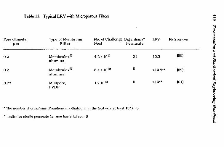
The relative efficiency of bacteria removal will, however, depend on the level of bacterial contamination and downstream processing require- ments. The filter ability to retain bacteria is commonly expressed in terms of the Log Reduction Value (LRV). The LRV is defined as the logarithm ofthe ratio of total microorganisms in the challenge to the microorganisms in the filtered fluid when a filter is subjected to a specific challenge. A 0.2 pm filter is challenged with Pseudonomas diminuta microorganisms and a 0.45 pm filter is challenged with Serratia marcescens using guidelines recommended by the Health Industry Manufacturers Association (HIMA).
Although cross-flow filtration can be effectively used for sterile filtration, dead end filtration can adequately serve these applications when the amount of contaminant is generally small (less than 1000 bacteridml). Cross-flow filtration may be more usefd when high loads (>1 O7 microorgan- isms/mL) of bacteria are involved requiring removal efficiency with a LRV value greater than 7.L6Ol At high bacterial loadings, there may be significant membrane fouling andor concentration polarization which could reduce flux and cause irreversible fouling. At high bacterial loadings, microporous membrane filters operating in the dead end configuration may be limited by low flux and require frequent cartridge replacement due to rapid pore
Table 12 shows the typical LRVvalues obtained using a polymeric and ceramic microfilter, Sterile filtration requires 100% bacteria retention by the membrane, whereas in many industrial bacteria removal applications the presence of a small quantity of bacteria in the filtrate may be acceptable. For example, drinking water obtained by microfiltration may contain nominal counts of bacteria in the filtrate which is then treated with a disinfectant such as chlorine or ozone. The use ofceramic filters may allow the user to combine the sterile filtration with steam sterilization in a single operation. This process can be repeated many times without changing filters due to their long service life (5 years or longer).
plugging.
330 F
ermentation and B
iochemical E
ngineering Handbook
3
ffi
P 3
Cross-Flow Filtration 331
7.5 Production of Pyrogen-free Water
Distillation was used in the past to produce high purity water. Distilled water is free from inorganic salts but may contain low-boiling organics. Water purity or quality can be measured by several analytical test methods. The most common water quality measure is its electrical resistance. Pure water resistivity is about 18 Mshms. A triple distilled watertypically shows a resistivity of only about 3 M-ohms. Today the combination of UF, RO, ion exchange and activated carbon is capable of producing 18 Mshms water.[8]
Ultrafiltration is used to remove pyrogens and other microorganisms from high purity water. Pyrogens are lipopolysaccharides (also known as endotoxins) withmolecular sizes ranging from 20,000 dalton (-0.005 pm) up to about 200,000 dalton (- 0.1 pm) produced from bacterial cell walls. Pyrogens induce fever when injected into animals or humans and cannot be removed by autoclaving or microfiltration.['1[62]
The lipopolysaccharide molecule is thermally unstable and destruction requires exposure to temperatures 25OOC and higher. Endotoxins can be removed using the principle of molecular size exclusion by reverse osmosis (RO) or ultrafiltration. Reverse osmosis can be used but may cause retention of low molecular weight salts which is highly undesirable in the preparation of certain non-pyrogenic parenteral solutions. [631 Ultrafiltration, on the other hand, with a 10,000 MWCO membrane can effectively remove pyrogens along with other microorganisms (not removed by prior separation tech- niques) without retaining salts.
Typical UF performance for pyrogen removal with a polymeric and ceramic membrane is shown in Table 13. It can be seen that both types of UF membranes can adequately remove pyrogens. The choice of UF membrane (ceramic or polymeric) will depend on operating conditions or other special process requirements. Ceramic membrane ultrafiltration can achieve a 5 log reduction in pyrogen level. These UF membranes have been validated for the production of water meeting the requirements of pyrogen-free water for injection (WFI) standards.[64]
332 F
ermentation and B
iochemical E
ngineering Handbook
4)
4 cc
0
2
0
E
Cross-Flow FiItration 333
8.0 GLOSSARY OF TERMS
Adsorption: It relates to the adherence of ions, molecules or particles with the membrane surfaces in contact (internal and external). In CFF this phenomenon could reduce the flux or change the retention characteristics. The tendency to form an adsorbed layer on the membrane surface may depend on the nature of the membrane surface. Typically hydrophilic surfaces adsorb less strongly than the hydrophobic surfaces, especially when organics are involved.
Asymmetric/composite membrane: This typically consist of a thin (0.5 to 20 microns) fine-pore layer responsible for separation and a support or substrate with single or multiple layers having progressively larger pores which provide the required mechanical strength. This type of structure maximizes the flux by minimizing the overall hydraulic resistance of the permeate (filtrate) flowing across the membrane structure.
Bacbpressure: It is the pressure generated by restricting retentate flow.
Bacbulse: This is achieved by rapid (typically lasting a fraction of a second) application of periodic counterpressure on the permeate side, typi- cally with the help of an automatic time switch or a microprocessor, to push back a specific (as low as possible) permeate volume in the opposite direction. It is used in many CFF applications (especially with ceramic membranes) as an effective technique to disrupt, reduce or destroy the concentration- polarization boundary layer. Backpulsing also helps to minimize particle/gel infiltration into the microporous structure. Typical backpulse frequencies (cycle times) are in the range of 3 to 10 minute .
Backwash: This is similar to the backpulse technique but is less intensive in terms of the pressures applied across the membrane to dislodge particles/gels from the membrane surface. Backpulse is typically carried out at pressures exceeding 4 bar and often in the range 6 to 10 bar, whereas a backwash is carried out at lower pressures (e.g., 2 to 3 bar).
Boundary layer: This refers to the layer adjacent to the membrane surface along the periphery of the feed channel. This contributes a major portion of the total resistance to transport and is often the controlling factor in determining the flux.
334 Fermentation and Biochemical Engineering Handbook
Bubble point: It relates to the largest pore diameter of the membrane. The bubble point is the smallest pressure difference at which the first gas bubbles appear from a liquid-saturated membrane pressurized by an inert gas. The bubble point test is also used for checking the physical integrity of the membrane for the presence of defects such as cracks or pinholes.
Cake layer: This refers tothe layer resulting from the physical deposition of solids, primarily on the membrane surface.
Channel: It is the opening or section of a module through which the fluid enters (feed) and exits (retentate). Most commercial modules have multiple lumens or channels.
Clean waterflux: It refers to the original flux of filtered deionized water with a virgin membrane. In most applications, after cleaning is performed the clean water flux is restored to approximately within 10% of its original value. It is seldom recovered to its original value after membrane cleaning due to monomolecular irreversible adsorption of foulants.
Concentration factor: The ratio of initial feed volume or weight to the volume or weight remaining at the end of filtration. The calculations differ for batch versus other modes such as batch feed-and-bleed or continuous cascade configuration.
Concentration polarization: This occurs when solutes or particles rejected by the membrane accumulate on or near the membrane surface. As a direct consequence ofthis condition, there is an increase in the resistance to solvent transport resulting in a flux decrease and possibly changes in the retention characteristics.
Continuous diafiltration: Under this mode of operation, water or other solution is continuously added to the feed or retentate at a rate equal to permeate rate.
Cross-flow velocity: This is the average rate ( d s or ft/sec) at which the feed or retentate flows parallel to the membrane surface.
Dynamic membrane: This type of membrane structure, also referred to as formed-in-place membrane, can be produced in several different ways. A commonly used technique involves introducing solutions of organic or
Cross-Flow Filtration 335
inorganic polyelectrolytes into the feed channel(s) and forming filtering layers on a porous support by applying a pressure difference. Another process uses the components in the feed stream itself to form a filtration layer (or cake).
Feed and bleed: A continuous mode of CFF where the feed is pumped into the recirculation loop at a rate which equals the summation ofthe permeation rate and the flow rate of retentate. It allows for increased control over the effect of concentration on the filtration performance.
Flow excursion: It describes the optimization of retentate flow at a constant transmembrane pressure.
Gel layer: This refers to the concentration polarization boundary layer with the highest solute (gel forming components of the feed) concentration.
Hydrophilic: A property characterized by a strong tendency to bind or adsorb water. Examples of hydrophilic materials are carbohydrates, vegetable gums, pectins and starches, and some complex proteins such as gelatin and collagen.
Hydrophobic: It is related to the water repelling property of a membrane material or a substance. This property is characteristic of all oils, fats, waxes, resins, as well as finely divided powders such as carbon black and magnesium carbonate.
Internalpore fouling: This is caused by the deposition of material inside the porous structure which often leads to significant flux decline and irreversible fouling. Internal pore fouling can be due to adsorption, precipitation, pore plugging or particle adhesion.
Membrane fouling: A phenomenon characteristic of all membrane-based filtration processes in which the membrane adsorbs or interacts with feed components. Membrane fouling causes a flux decrease and may also increase the retention ofcertain components in the feed. Membrane fouling is typically a time-dependent phenomenon and often independent of concentration. In some situations a partial dependence on concentration may be observed.
336 Fermentation and Biochemical Engineering Handbook
Molecular weight cutof It refers to be smallest molecular weight of a macrosolute for which the membrane shows at least 90% rejection. This value is typically determined under a set of well-defined conditions using model compounds (e.g., polyethylene glycols, dextrans and proteins such as BSA) at low concentration.
Normalizedflux: Permeation rate per unit filtering surface, normalized to a given set of operating conditions such as constant temperature, pressure and/ or concentration.
Permeability: This is defined as flux per unit transmembrane pressure for a given solvent at a fixed temperature. It differs from process flux and should only be used with respect to clean liquids.
Pressure excursion: This refers to the incremental increases in transmem- brane pressure while maintaining a constant retentate flow.
Rejection or retention coeflcient: Th i s describes the ability ofthe membrane to retain the desired species from the feed on the membrane surface. Since the rejection is often dependent on membrane characteristics and operating parameters, these must be clearly stated sothat a fair comparison can be made between different types of membranes for a given application. It is defined as: R = 1- C,/C,, where, Cp is the concentration of the species in permeate and C, is its concentration in the retentate. If a significant passage of the species occurs, then an average concentration is used.
Reynold’s number: It describes the nature of hydraulic regime such as laminar flow, transitional flow or turbulent flow. It is defined as the ratio of the product of hydraulic diameter and mass flow velocity to that of fluid viscosity. Mass velocity is the product of cross-flow velocity and fluid density. Laminar flow exists for Reynold’s numbers below 2000 whereas turbulent is characterized by Reynold’s numbers greater than 4000.
Retentate: It refers to that portion of the feed that does not cross the filtering surface in a single pass. It is also described as concentrate since in many situations the depleting particle-free permeate leaves higher solids in the retentate stream.
Cross- Flow Filtration 33 7
Transmembrane pressure: It is the average driving force for permeation across the membrane, Neglecting osmotic pressure effects for most MF/UF applications, it is defined as the difference between the average pressure on the feed (or retentate) side and that on the permeate (or shell side).
Zeta potential: It relates to the electrokinetic potential across the interface of all solids and liquids and specifically to that of the diffise layer of ions surrounding a charged colloidal particle. Such a diffise aggregation of positive and negative electric charges surrounding a suspended colloidal particle is largely responsible for colloidal stability.
ACKNOWLEDGMENT
The author wants to thank Dr. H. S. Muralidhara for his careful review of the manuscript. He also made many useful suggestions and some contributions pertaining to the discussions on membrane fouling, cleaning and concentration polarization.
338 Fermentation and Biochemical Engineering Handbook
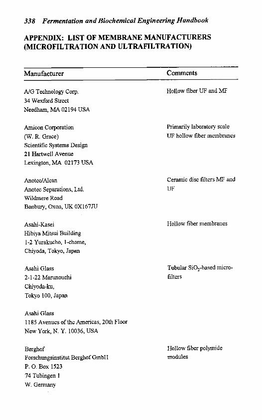
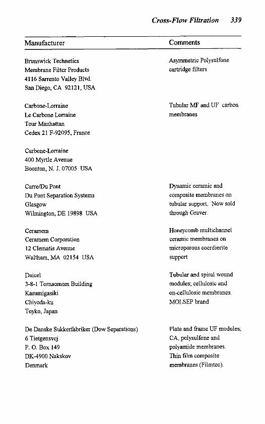
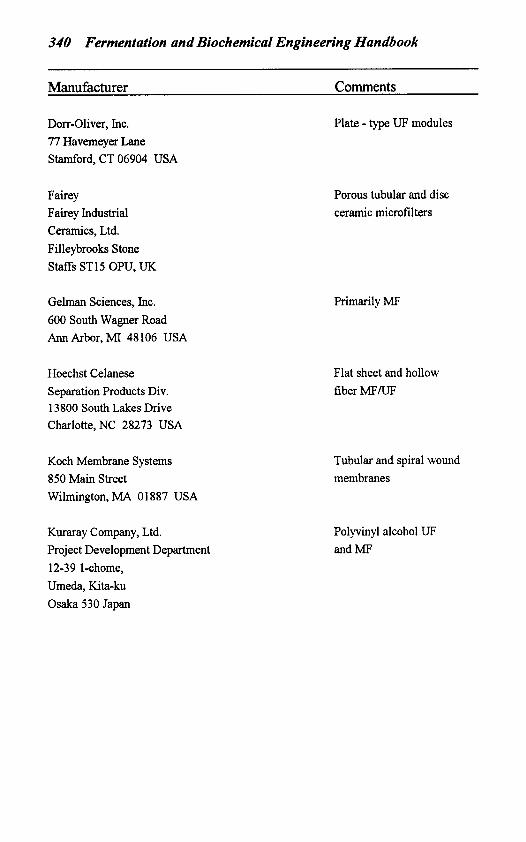
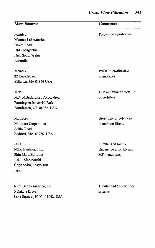
APPENDIX: LIST OF MEMBRANE MANUFACTURERS (MICROFILTRATION AND ULTRAFILTRATION)
Manufacturer Comments
A/G Technology Corp. 34 Wexford Street Needham, MA 02 194 USA
Amicon Corporation (W. R. Grace) Scientific Systems Design 2 1 Hartwell Avenue Lexington, MA 02173 USA
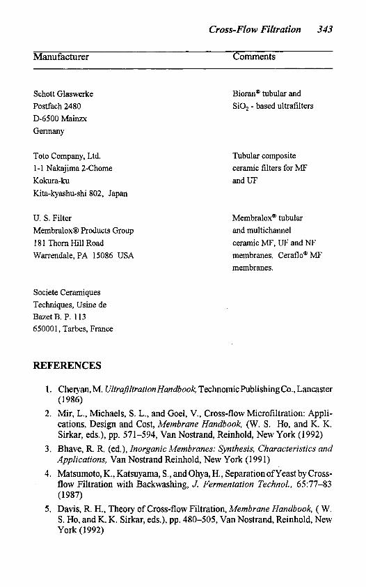
Toto Company, Ltd. 1-1 Nakajima 2-Chome Kokura-ku Kita-kyashu-shi 802, Japan
U. S. Filter MembraloxB Products Group 18 1 Thorn Hill Road Warrendale, PA 15086 USA
Bioran@ tubular and SiO, - based ultrafilters
Tubular composite ceramic filters for MF and UF
Membralox@ tubular and multichannel ceramic MF, UF and NF membranes. Ceraflo@ MF membranes.
Societe Ceramiques Techniques, Usine de Bazet B. P. 113 65000 1, Tarbes, France
REFERENCES
1. Cheryan, M. Ultrafiltration Handbook, Technomichblishing Co., Lancaster ( 1986)
2. Mir, L., Michaels, S. L., and Goel, V., Cross-flow Microfiltration: Appli- cations, Design and Cost, Membrane Handbook, (W. S . Ho, and K. K. Sirkar, eds.), pp. 571-594, Van Nostrand, Reinhold, New York (1 992)
3. Bhave, R. R. (ed.), Inorganic Membranes: Synthesis, Characteristics and Applications, Van Nostrand Reinhold, New York (1991)
4. Matsumoto, K., Katsuyama, S., and Ohya, H., Separation ofyeast by Cross- flow Filtration with Backwashing, J. Fermentation Techno]., 65:77-83 (1987)
5 . Davis, R. H., Theory of Cross-flow Filtration, Membrane Handbook, ( W . S . Ho, and K. K. Sirkar, eds.), pp. 480-505, Van Nostrand, Reinhold, New York (1992)
344 Fermentation and Biochemical Engineering Handbook
6. Michaels, S. L., Cross-flow Microfilters, Chemical Eng., pp. 84-91 (Jan.,
7. Kulkarni, S. S., Funk, E. W., and Li, N. N., Ultrafiltration, in Membrane Handbook (W. S . Ho and K. K. Sirkar, eds.) pp. 391-453, Van Nostrand, Reinhold, New York (1992)
8. Schweitzer, P. A. (ed.), Handbook of Separation Techniques for Chemical Engineers, pp. 2-3 to 2-103 McGraw-Hill, New York (1979)
9. Hsieh, H. P., General Characteristics of Inorganic Membranes, (R. R. Bhave, ed.), Inorganic Membranes: Synthesis, Characteristics and Appli- cations, Van Nostrand, Reinhold, New York (1991)
10. Paulson, D. J., Wilson, R. L, and Spatz, D. D., Cross-flow Membrane Technology and its Applications, Food Technology, 77-1 11 @ec., 1984)
11. Burggraaf, A. J. and Keizer, K., Synthesis of Inorganic Membranes, Inorganic Membranes: Synthesis, Characteristics andApplications, (R. R. Bhave, ed.), Van Nostrand, Reinhold, New York (1991)
12. O’Sullivan, T. J., Epstein, A. C., Korchin, S. R., and Beaten, N. C., Applications of Ultrafiltration in Biotechnology, Chem. Eng. Progress, 68- 75 (Jan., 1984)
13. Ng, P., Lundblad, J., and Mitra, G., Optimization of Solute Separation by Diafiltration, Separation Science, 11(5):499-502 (1976)
14. Breslau, B. R., The Theory and Practice of Ultrafiltration, Proc. Scientific Conference Corn-Refiners Association, Food and Food Chemistry, 17:36- 90 (1982)
15. Epstein, A. C., Batch Versus Continuous Systems for Ultrafiltration, Proc. Fifth Annual Membrane Technology Planning Conference, Cambridge (1987)
16. Taniguchi, M., Kotani, N., and Kobayashi, T., High-Concentration Culti- vation of Lactic Acid Bacteria in Fermenter with Cross-flow Filtration, J. Fermentation Technol., 65(2): 179-84 (1987)
17. Ripperger, S. and Schulz, G., Microporous Membranes in Biotechnical Application, Bioprocess Engineering, 1 :43-49 (1986)
18. Olesen, N. and Jensen, F., Microfiltration: The Influence of Operation Parameters on the Process, Michwissenschajl, 44(8):476-79.
19. Sandblom, R. M., Filtering Process, U. S. Patent 4,105,547 (Aug. 8, 1978) 20. Blatt, W.E.,Dravid, A.,Michaels, A. S., andNelson,L., SolutePolarization
and Cake Formation in Membrane Ultrafiltration: Causes, Consequences and Control Techniques, Membrane Science and Technology, (J. E. Flinn, ed.), Plenum Press, New York (1970)
21. Matsumoto, K., Kawahara, M., and Ohya, H., Cross-Flow Filtration of Yeast by Microporous Ceramic Membrane with Backwashing, J. Ferment. Technol., 66(2):199-205 (1988)
1989)
Cross-Flow Filtration 345
22. Bennasar, M. andTarodo de IaFuente, B., Model ofthe Fouling Mechanism and of the Working of a Mineral Membrane in Tangential Filtration, Sciences Des Ailments, 7:647455 (1987)
23. Glimenius, R., Microfiltration-State ofthe Art, Desalination, 53:363-372 (1 985)
24. Beechold, H., Ultrafiltration and Electro-Ultrafiltration, Colloid Chemis- fry, Vol. 1, (J. Alexander, ed.), The Chemical Catalog Company (1926)
25. Belfort, G., Membrane Modules; Comparisons of Different Configurations Using Fluid Mechanics; J. Membrane Sci., 35:245-270 (1988)
26. Brian, P. L. T., Concentration Polarization in Reverse Osmosis Desalina- tion with Variable Flux and Incomplete Salt Rejection, Ind. Chem. Fund., 4:438-445 (1965)
27. Rios, G. M., Rakotoarisoa, M., and Tarodo de la Fuente, B., Basic Transport Mechanisms of Ultrafiltration in the Presence of Fluidized Particles, J. Membrane Sci., 34:331-343 (1987)
28. Langer, P. and Schnabel, R., Porous Glass Membranes for Downstream Processing, Chem. Biochem. Eng. Q., 2(4):242-244 (1988)
29. Langer, P., Breitenbach, S., and Schnabel, R., Ultrafiltration with Porous Glass Membranes, Proc. Int. Techn. Conj on Membrane Separation Processes, Brighten, U. K. (May 24-26, 1989)
30. Hodgson, P. H. andFane, A. G., Cross-flow Microfiltration ofBiomass with Inorganic Membranes: The Influence of Membrane Surface and Fluid Dynamics, Key Engineering Materials, 61,62: 167-174 (1992)
31. Mermann, C. C., High Frequency Excitation and Vibration Studies on Hyperfiltration Membranes, Desalination, 42:329-338 (1982)
32. Muralidhara, H. S., The Combined Field Approach to Separations, Chem. Tech., 224-235 (1988)
33. Bier, M. (ed.), Electrophoresis, Vol. 1, p. 263, Academic Press, New York (1959)
34. Henry, J. D., Lawler, L. F., and Kuo, C. H. A., A Solid/Liquid Separation Process Based on Cross-Flow and Electrofiltration, A. I. Ch. E. Journal,
35. Muralidhara, H. S., Membrane Fouling: Techno-Economic Implications, Proceedings of the Second International Conference on Inorganic Mem- branes, pp. 301-306, Trans Tech Publications, Zurich (1991)
36. Attia, H., Bennasar, M., and Trodo de la Fuente, B., Study of the Fouling of Inorganic Membranes by Acidified Milks Using Scanning Electron Microscopy and Electrophoresis, J. of Dairy Research, 58:39-50 (199 1)
37. Knez, Z., Ultrafiltration Processes in Biotechnology, Proc. Filtech Confer- ence, pp. 194-203 (1987)
23(6):85 1-859 (1977)
346 Fermentation and Biochemical Engineering Handbook
38. Johnson, J. N., Cross-flow Microfiltration Using Polypropylene Hollow Fibers, Fifrh Annual Membrane Technology Planning Conference, Cam- bridge ( a t . 1987)
39. Mateus, M. and Cabral, J. M. S., Pressure-Driven Membrane Processes for Steroid Bioseparation: A Comparison of Membrane, Hydrodynamic and Operating Aspects, Bioseparation, 2:279-287 (199 1)
40. Raaska, E., Cell Harvesting with Tangential Flow Filtration: Optimization of Tangential Flow, Proc. Membrane Technology Group Symposium, Tylosand, Sweden (May 28-30, 1985)
41. Hsieh, H. P., Bhave, R. R. and Fleming, H. L., Microporous Alumina Membranes, J. Membrane Science, 39:221-241 (1988)
42. Muller, W., MicrofiltrationProcess and Apparatus, U. S. Patent, 5,076,93 1 @ec. 31,1991)
43. Merin, U. and Daufh, G., Separation Processes Using Inorganic Mem- branes in the Food Industry, Proc. of the First International Conference on Inorganic Membranes, pp. 27 1-28 1, Montpelier (1989)
44. Gabler, R. and Messinger, S., Scaling-up Membrane Filter Systems, Chem Tech., pp. 616-621 (Oct., 1986)
45. Haggin, J., Membranes Play Growing Role in Small-Scale Industrial Processing, Chem. & Eng. News, pp. 23-32 (July 11,1988).
46. Bhave, R. R., Guibaud, J., Tarodo de la Fuente, B., and Venkataraman, V. K., Inorganic Membranes in Food and Biotechnology Applications, (R. R. Bhave, ed.), Inorganic Membranes: Synthesis, Characteristics and Appli- cations, Van Nostrand, Reinhold, New York (1991)
47. Inman, F. N., Filtration and Separation in Antibiotic Manufacture, Proc. Filtration Society, London (Jan. 24, 1984)
48. Ripperger, S., Schultz, G., and Pupa, W., Membrane Separation Processes, Biotechnology, Proc. Fifth Annual Membrane Technology Planning Con- ference, Cambridge (Oct., 1987)
49. Tutunjan, R. A. and Breslau, R., Pharm. Tech. Conference, New York ( 1982)
50 Melling, J., Process. Biochem., 9:7 (Sept., 1974) 51. Gerster, D. and Veyre, R., Mineral Ultrafiltration Membranes in Industry,
Reverse Osmosis and Ultrajltration, ( S . Sourirajan, and T. Matswura, eds.), pp, 225-30, h e r . Chem. Soc., Washington, D.C. (1985)
52. Belter, P. A., Cussler, E. L., andHu, W. S . , Bioseparations: Downstream Processing for Biotechnology, John Wiley, New York (1988)
53. Leiva, M. L. and Tragardh, G., Chem. Tech., 35(8):381 (1983) 54. Lasky, M. and Grant, D., Use of Microporous Hollow Fiber Membranes in
Cell Harvesting, Analytical Laboratory, pp. 16-2 1 (Nov./Dec., 1985) 55. Bjurstrom, E., Chemical Eng., (Feb. 18, 1985)
Cross-Flow Filtration 347
56. Boyaval, P. and Corre, C., Biofechnol. Lett., 9(11):801 (1987) 57. Minnier, M., Ferras, E., Goma, G., and Soucaille, P., presented at the VI1
International Biotechnology Symposium, New Delhi (1984) 58. Hoffmann, H., Scheper, T. and Schugerl, K., Use ofMembranes to Improve
Bioreactor Performance, Chemical Eng, J., 34:B13-B19 (1987) 59. Morgart, J. R., Filson, J. L., Peters, J., and Bhave, R. R., Bacteria Removal
by Ceramic Microfiltration, U. S. Patent #5,242,595 (1993) 60. Leahy, T. J. and Sullivan, M. J., Validation ofBacterial-Retention Capabili-
ties of Membrane Filters, Pharm Tech., 2(11):65-75 (1978) 61. Goel, V., Accomazzo, M. A., DiLeo, A. J., Meier, P., Pitt, A., and Pluskal,
M., Deadend Microfiltration; Applications, Design and Cost, Membrane Handbook, (W. S. Ho, and K. K. Sirkar, 4 s . ) pp. 506-570, Van Nostrand, Reinhold, New York (1992)
62. Filson, J. L., Bhave, R. R., Morgart, J., and Graaskamp, J., Pyrogen Separations by Ceramic Ultrafiltration, U. S. Patent 5,047,155 (1991)
63. Allegra, A. E., Jr. and Goel, V., Virus removal from therapeutic proteins, IMSTEC 1992 Conference, Sydney (Nov., 1992)
64. Reinholz, W., Making Water for Injection with Ceramic Membrane Ultra- filtration, Pharm. Tech., pp. 84-96 (Sep., 1995)


![Index [ftp.feq.ufu.br]ftp.feq.ufu.br/Luis_Claudio/Books/E-Books... · Aeration-agitation 20, 46 Aeration-agitation bioreactor 58, 62 Aerobic fermentation 3, 18 1 Aerobic metabolic](https://static.documents.pub/doc/80x56/5ecd4084c5979741945851bb/index-ftpfequfubrftpfequfubrluisclaudiobookse-books-aeration-agitation.jpg)


