SERIES 682XXB/683XXB SYNTHESIZED SIGNAL GENERATORS SCPI PROGRAMMING MANUAL P/N: 10370-10288 REVISION: E PRINTED: OCTOBER 1997 COPYRIGHT 1994 ANRITSU CO. 490 JARVIS DRIVE MORGAN HILL, CA 95037-2809
Transcript
SERIES682XXB/683XXB
SYNTHESIZED SIGNAL GENERATORS
SCPI PROGRAMMING MANUAL
P/N: 10370-10288REVISION: E
PRINTED: OCTOBER 1997COPYRIGHT 1994 ANRITSU CO.
490 JARVIS DRIVEMORGAN HILL, CA 95037-2809
WARRANTYThe ANRITSU product(s) listed on the title page is (are) warranted against defects in materials andworkmanship for one year from the date of shipment, except for YIG-tuned oscillators and all AN-RITSU manufactured microwave components, which are warranted for two years.
ANRITSU’s obligation covers repairing or replacing products which prove to be defective during thewarranty period. Buyers shall prepay transportation charges for equipment returned to ANRITSUfor warranty repairs. Obligation is limited to the original purchaser. ANRITSU is not liable for con-sequential damages.
LIMITATION OF WARRANTYThe foregoing warranty does not apply to ANRITSU connectors that have failed due to normal wear.Also, the warranty does not apply to defects resulting from improper or inadequate maintenance bythe Buyer, unauthorized modification or misuse, or operation outside of the environmental specifica-tions of the product. No other warranty is expressed or implied, and the remedies provided hereinare the Buyer’s sole and exclusive remedies.
TRADEMARK ACKNOWLEDGEMENTSAdobe Acrobat is a registered trademark of Adobe Systems Incorporated.
NOTICEANRITSU Company has prepared this manual for use by ANRITSU Company personnel and cus-tomers as a guide for the proper installation, operation, and maintenance of ANRITSU Companyequipment and computor programs. The drawings, specifications, and information contained hereinare the property of ANRITSU Company, and any unauthorized use or disclosure of these drawings,specifications, and information is prohibited; they shall not be reproduced, copied, or used in wholeor in part as the basis for manufacture or sale of the equipment or software programs without theprior writtten consent of WILTRON Company.
1-1 SCOPE OF MANUAL This manual provides information for remote operation of the Series682XXB/683XXB Synthesized Signal Generators using commands sentfrom an external controller via the IEEE-488 General Purpose Inter-face Bus (GPIB). It includes the following:
q A general description of the GPIB and the bus data transfer andcontrol functions.
q A listing of the IEEE-488 Interface Function Messages recog-nized by the signal generator with a description of its response.
q A complete listing and description of all the Standard Commandsfor Programmable Instruments (SCPI) commands that can beused to control signal generator operation with examples of com-mand usage.
This manual is intended to be used in conjunction with the Series682XXB/683XXB Synthesized Signal Generators Operation Manual,P/N 10370-10284. Refer to that manual for general information aboutthe 682XXB/683XXB, including equipment set up and front panel(manual mode) operating instructions.
ElectronicManual
This manual is available on CD ROM as an AdobeAcrobat Portable Document Format (*.pdf) file. Thefile can be viewed using Acrobat Reader, a free pro-gram that is also included on the CD ROM. The fileis “linked” such that the viewer can choose a topic toview from the displayed “bookmark” list and “jump”to the manual page on which the topic resides. Thetext can also be word-searched. Contact ANRITSUCustormer Service for price and availability.
GPIB Pro-grammingManual
In addition to the SCPI programming commands de-scribed in this manual, the signal generator’s GPIBinterface also accepts and implements a set of682XXB/683XXB GPIB Product-Specific (“NATIVE”)commands. These GPIB commands are listed anddescribed in the Series 682XXB/683XXB Synthe-sized Signal Generators GPIB Programming Man-ual, P/N 10370-10286.
682XXB/683XXB SCPI PM 1-3
1-4 682XXB/683XXB SCPI PM
GENERAL GPIB IEEE-488 INTERFACEINFORMATION BUS DESCRIPTION
HANDSHAKE Lines(3 signal lines)
(5 signal lines)
DATA L INES
Data Byte Transfer Control Bus
Data Bus
General InterfaceManagement Bus
IEEE-488 BUS (16 Lines)
(8 signal lines)
Management CONTROL Lines
D EVI C E A
Able to talk, listen,and control(e.g. COMPUTER)
DEVICE B
Able to talk and listen(e.g. 682XXB/683XXBSIGNALGENERATOR)
D EVI C E D
Only able to talk (e.g. OTHER INSTRUMENT**)
DAV - DATA VALID
NRFD - NOT READY FO R DATA*NDAC - NOT DATA ACCEPTED*
IFC - INTERFACE CLEAR
ATN - ATTENTIONSRQ - SERVICE REQUEST
REN - REMOTE ENABLE
EOI - END OR IDENTIFY
D EVI C E C
Only able to listen(e.g. OTHER INSTRUMENT**)
DATA INPUT/OUTPUT, DIO 1 thru DIO 8
* NEGATION IS REPRESENTED BY LO W S T AT E O N T HES E T WO LI N ES** IF USED
Figure 1-1. Interface Connections and GPIB Bus Structure
1-2 INTRODUCTION This chapter provides a general description of the GPIB and the busdata transfer and control functions. It also contains a listing of the682XXB/683XXB’s GPIB interface function subset capability and re-sponse to IEEE-488 interface function messages.
The GPIB information presented in this chapter is general in nature.For complete and specific information, refer to the following docu-ments: ANSI/IEEE Std 488.1-1987 IEEE Standard Digital Interfacefor Programmable Instrumentation and ANSI/IEEE Std 488.2-1987IEEE Standard Codes, Formats, Protocols and Common Commands.These documents precisely define the total specification of the me-chanical and electrical interface, and of the data transfer and controlprotocols.
1-3 IEEE-488 INTERFACEBUS DESCRIPTION
The IEEE-488 General Purpose Interface Bus (GPIB) is an instrumen-tation interface for integrating instruments, computers, printers, plot-ters, and other measurement devices into systems. The GPIB uses 16signal lines to effect transfer of information between all devices con-nected on the bus.
The following requirements and restrictions apply to the GPIB.
q No more than 15 devices can be interconnected by one contiguousbus; however, an instrumentation system may contain more thanone interface bus.
q The maximum total cumulative cable length for one interface busmay not exceed twice the number of devices connected (in me-ters), or 20 meters—whichever is less.
q A maximum data rate of 1 Mb/s across the interface on any sig-nal line.
q Each device on the interface bus must have a unique address,ranging from 00 to 30.
The devices on the GPIB are connected in parallel, as shown in Figure1-1. The interface consists of 16 signal lines and 8 ground lines in ashielded cable. Eight of the signal lines are the data lines, DIO 1 thruDIO 8. These data lines carry messages (data and commands), onebyte at a time, among the GPIB devices. Three of the remaining linesare the handshake lines that control the transfer of message bytes be-tween devices. The five remaining signal lines are referred to as inter-face management lines.
The following paragraphs provide an overview of the GPIB including adescription of the functional elements, bus structure, bus data transferprocess, interface management bus, device interface function require-ments, and message types.
682XXB/683XXB SCPI PM 1-5
GENERAL GPIB IEEE-488 INTERFACEINFORMATION BUS DESCRIPTION
FunctionalElements
Effective communications between devices on theGPIB requires three functional elements; a talker, alistener, and a controller. Each device on the GPIB iscategorized as one of these elements depending onits current interface function and capabilities.
TalkerA talker is a device capable of sending device-dependent data to another device on the bus whenaddressed to talk. Only one GPIB device at a timecan be an active talker.
ListenerA listener is a device capable of receiving device-dependent data from another device on the buswhen addressed to listen. Any number of GPIB de-vices can be listeners simultaneously.
ControllerA controller is a device, usually a computer, capableof managing the operation of the GPIB. Only oneGPIB device at a time can be an active controller.The active controller manages the transfer ofdevice-dependent data between GPIB devices bydesignating who will talk and who will listen.
System ControllerThe system controller is the device that always re-tains ultimate control of the GPIB. When the sys-tem is first powered-up, the system controller is theactive controller and manages the GPIB. The sys-tem controller can pass control to a device, makingit the new active controller. The new active control-ler, in turn, may pass control on to yet another de-vice. Even if it is not the active controller, thesystem controller maintains control of the InterfaceClear (IFC) and Remote Enable (REN) interfacemanagement lines and can thus take control of theGPIB at anytime.
1-6 682XXB/683XXB SCPI PM
GENERAL GPIB IEEE-488 INTERFACEINFORMATION BUS DESCRIPTION
BusStructure
The GPIB uses 16 signal lines to carry data andcommands between the devices connected to thebus. The interface signal lines are organized intothree functional groups.
q Data Bus (8 lines)q Data Byte Transfer Control Bus (3 lines)q General Interface Management Bus (5 lines)
The signal lines in each of the three groups are des-ignated according to function. Table 1-1 lists thesedesignations.
Data BusDescription
The data bus is the conduit for the transfer of dataand commands between the devices on the GPIB. Itcontains eight bi-directional, active-low signal lines—DIO 1 thru DIO 8. Data and commands are trans-ferred over the data bus in byte-serial, bit-parallelform. This means that one byte of data (eight bits) istransferred over the bus at a time. DIO 1 representsthe least-significant bit (LSB) in this byte andDIO 8 represents the most-significant bit (MSB).Bytes of data are normally formatted in seven-bitASCII (American Standard Code for Information In-terchange) code. The eighth (parity) bit is not used.
Each byte placed on the data bus represents either acommand or a data byte. If the Attention (ATN) in-terface management line is TRUE while the data istransferred, then the data bus is carrying a buscommand which is to be received by every GPIB de-vice. If ATN is FALSE, then a data byte is beingtransferred and only the active listeners will receivethat byte.
682XXB/683XXB SCPI PM 1-7
GENERAL GPIB IEEE-488 INTERFACEINFORMATION BUS DESCRIPTION
Bus TypeSignal Line
NameFunction
Data Bus DIO1–DIO8 Data Input/Output, 1 thru 8
Data ByteTransferControl Bus
DAVNRFDNDAC
Data AvailableNot Ready For DataNot Data Accepted
GeneralInterfaceManagementBus
ATNIFCSRQRENEOI
AttentionInterface ClearService RequestRemote EnableEnd Or Identify
Table 1-1. Interface Bus Signal Line Designations
Data ByteTransferControl BusDescription
Control of the transfer of each byte of data on thedata bus is accomplished by a technique called the“three-wire handshake”, which involves the threesignal lines of the Data Byte Transfer Control Bus.This technique forces data transfers at the speed ofthe slowest listener, which ensures data integrity inmultiple listener transfers. One line (DAV) is con-trolled by the talker, while the other two (NRFD andNDAC) are wired-OR lines shared by all active lis-teners. The handshake lines, like the other GPIBlines, are active low. The technique is describedbriefly in the following paragraphs and is depictedin Figure 1-2. For further information, refer toANSI/IEEE Std 488.1.
DAV (Data Valid)This line is controlled by the active talker. Beforesending any data, the talker verifies that NDAC isTRUE (active low) which indicates that all listenershave accepted the previous data byte. The talkerthen places a byte on the data lines and waits untilNRFD is FALSE (high) which indicates that all ad-dressed listeners are ready to accept the informa-tion. When both NRFD and NDAC are in the properstate, the talker sets the DAV line TRUE (activelow) to indicate that the data on the bus is valid(stable).
NRFD (Not Ready For Data)This line is used by the listeners to inform thetalker when they are ready to accept new data. Thetalker must wait for each listener to set the NRFD
1-8 682XXB/683XXB SCPI PM
GENERAL GPIB IEEE-488 INTERFACEINFORMATION BUS DESCRIPTION
1st Data Byte 2nd Data Byte
ValidNot
ValidValid
NotValid
AllReady
NoneReady
AllReady
NoneReady
AllAccept
NoneAccept
NoneAccept
AllAccept
DIO1-DIO8(composite)
DAV
NRFD
NDAC
Figure 1-2. Typical GPIB Handshake Operation
line FALSE (high) which they will do at their ownrate. This assures that all devices that are to acceptthe data are ready to receive it.
NDAC (Not Data Accepted)This line is also controlled by the listeners and isused to inform the talker that each device addressedto listen has accepted the data. Each device releasesNDAC at its own rate, but NDAC will not go FALSE(high) until the slowest listener has accepted thedata byte.
GeneralInterfaceManagementBusDescription
The general interface management bus is a group offive signal lines used to manage the flow of informa-tion across the GPIB. A description of the function ofeach of the individual control lines is provided be-low.
ATN (Attention)The active controller uses the ATN line to definewhether the information on the data bus is a com-mand or is data. When ATN is TRUE (low), the busis in the command mode and the data lines carrybus commands. When ATN is FALSE (high), the busis in the data mode and the data lines carry device-dependent instructions or data.
EOI (End or Identify)The EOI line is used to indicate the last byte of amultibyte data transfer. The talker sets the EOI lineTRUE during the last data byte.
The active controller also uses the EOI line in con-junction with the ATN line to initiate a parallel pollsequence.
IFC (Interface Clear)Only the system controller uses this line. When IFCis TRUE (low), all devices on the bus are placed in aknown, quiescent state (unaddressed to talk, unad-dressed to listen, and service request idle).
REN (Remote Enable)Only the system controller uses this line. WhenREN is set TRUE (low), the bus is in the remotemode and devices are addressed either to listen or totalk. When the bus is in remote and a device is ad-dressed, it receives instructions from the GPIBrather than from its front panel. When REN is setFALSE (high), the bus and all devices return to localoperation.
682XXB/683XXB SCPI PM 1-9
GENERAL GPIB IEEE-488 INTERFACEINFORMATION BUS DESCRIPTION
SRQ (Service Request)The SRQ line is set TRUE (low) by any device re-questing service by the active controller.
DeviceInterfaceFunctionCapability
An interface function is the GPIB system elementwhich provides the basic operational facility throughwhich a device can receive, process, and send mes-sages. Each specific interface function may onlysend or receive a limited set of messages within par-ticular classes of messages. As a result, a set ofinterface functions is necessary to achieve completecommunications among devices on the GPIB.ANSI/IEEE Std 488.1 defines each of the interfacefunctions along with its specific protocol.
ANSI/IEEE Std 488.2 specifies the minimum set ofIEEE 488.1 interface capabilities that each GPIBdevice must have. This minimum set of interfacefunctions assures that the device is able to send andreceive data, request service, and repond to a deviceclear message. Table 1-2 lists the interface functioncapability of the series 682XXB/683XXB signal gen-erators.
1-10 682XXB/683XXB SCPI PM
GENERAL GPIB IEEE-488 INTERFACEINFORMATION BUS DESCRIPTION
FunctionIdentifier
Function 682XXB/683XXB Capability
AH1 Acceptor Handshake Complete Capability
SH1 Source Handshake Complete Capability
T6 Talker No Talk Only (TON)
L4 Listener No Listen Only (LON)
SR1 Service Request Complete Capability
RL1 Remote/Local Complete Capability
PP1 Parallel Poll Complete Capability
DC1 Device Clear Complete Capability
DT1 Device Trigger Complete Capability
C0, 1, 2, 3,28
Controller CapabilityOptions
C0, No Capability;C1, System Controller;C2, Send IFC and Take Charge;C3, Send REN;C28, Send IF Messages
E2 Tri-State Drivers Three-state bus drivers
Table 1-2. 682XXB/683XXB Interface Function Capability
MessageTypes
There are three types of information transmittedover the GPIB—interface function messages,device-specific commands, and data and instrumentstatus messages.
Interface Function MessagesThe controller manages the flow of information onthe GPIB using interface function messages, usuallycalled commands or command messages. Interfacefunction messages perform such functions as initial-izing the bus, addressing and unaddressing devices,and setting device modes for remote or local opera-tion.
There are two types of commands—multiline anduniline. Multiline commands are bytes sent by theactive controller over the data bus (DIO1-DIO8)with ATN set TRUE. Uniline commands are signalscarried by the individual interface managementlines.
The user generally has control over these com-mands; however, the extent of user control dependson the implementation and varies with the specificGPIB interface hardware and software used withthe external controller.
Device-Specific CommandsThese commands are keywords or mnemonic codessent by the external controller to control the setupand operation of the addressed device or instru-ment. The commands are normally unique to a par-ticular instrument or class of instruments and aredescribed in its documentation.
Device-specific commands are transmitted over thedata bus of the GPIB to the device in the form of AS-CII strings containing one or more keywords orcodes.They are decoded by the device’s internal con-troller and cause the various instrument functionsto be performed.
Data and Instrument Status MessagesThese messages are sent by the device to the exter-nal controller via the GPIB. They contain measure-ment results, instrument status, or data files thatthe device transmits over the data bus in responseto specific requests from the external controller. Thecontents of these messages are instrument specificand may be in the form of ASCII strings or binarydata.
682XXB/683XXB SCPI PM 1-11
GENERAL GPIB IEEE-488 INTERFACEINFORMATION BUS DESCRIPTION
In some cases data messages will be transmittedfrom the external controller to the device. For exam-ple, messages to load calibration data.
An SRQ (service request) is an interface functionmessage sent from the device to the external control-ler to request service from the controller, usuallydue to some predetermined status condition or error.To send this message, the device sets the SRQ lineof the General Interface Management Bus true,then sends a status byte on the data bus lines.
An SRQ interface function message is also sent bythe device in response to a serial poll message fromthe controller, or upon receiving an Output StatusByte(s) command from the controller. The protocolsassociated with the SRQ functions are defined in theANSI/IEEE Std 488.2 document.
The manner in which interface function messagesand device-specific commands are invoked in pro-grams is implementation specific for the GPIB inter-face used with the external controller. Even thoughboth message types are represented by mnemonics,they are implemented and used in different ways.
Normally, the interface function messages are sentautomatically by the GPIB driver software in re-sponse to invocation of a software function. For ex-ample, to send the IFC (Interface Clear) interfacefuction message, one would call the ibsic function ofthe National Instruments software driver. On theother hand, the command *RST (Reset) is sent in acommand string to the addressed device. In the caseof the National Instruments example, this would bedone by using the ibwrt function call.
1-12 682XXB/683XXB SCPI PM
GENERAL GPIB IEEE-488 INTERFACEINFORMATION BUS DESCRIPTION
1-4 682XXB/683XXB GPIBOPERATION
All Series 682XXB/683XXB Synthesized Signal Generator functions,settings, and operating modes (except for power on/standby) are con-trollable using commands sent from an external controller via theGPIB. When in the remote (GPIB) mode, the signal generator func-tions as both a listener and a talker. The GPIB interface function ca-pability of the 682XXB/683XXB is listed in Table 1-2 (page 1-10).
Setting GPIBOperatingParameters
The 682XXB/683XXB leaves the factory with theGPIB address value set to 5 and the data delimitingterminator set to carriage return and line feed(CR/LF). A different address value can be enteredfrom the front panel using the Configure GPIBmenu. Using this same menu, the data delimitingterminator can be changed to carriage return (CR)only. Refer to Chapter 2 of the Series 682XXB/683XXB Synthesized Signal Generators OperationManual for the procedure.
Selecting theInterfaceLanguage
Series 682XXB/683XXB Synthesized Signal Genera-tors with Option 19 can be remotely operated usingone of two external interface languages—Native orSCPI. The Native interface language uses a set of682XXB/683XXB GPIB Product Specific commandsto control the instrument; the SCPI interface lan-guage uses a set of the Standard Commands for Pro-grammable Instruments commands to control theunit. Selecting which of these external interface lan-guages is to be used can be made from the frontpanel using the Configure GPIB menu. Refer topage 2-11 for the procedure.
Response toGPIB Inter-face Func-tion Mes-sages
Table 1-3 (page 1-14) lists the GPIB Interface Func-tion Messages that the 682XXB/683XXB will recog-nize and respond to. With the exception of theDevice Clear and Selected Device Clear messages,these messages affect only the operation of the682XXB/683XXB GPIB interface. The signal genera-tor’s response for each message is indicated.
Interface function messages are transmitted on theGPIB data lines and interface management lines aseither unaddressed or addressed commands. Themanner in which these messages are invoked in pro-grams is implementation dependent. For program-ming information, refer to the documentationincluded with the GPIB Interface used for the exter-nal controller.
682XXB/683XXB SCPI PM 1-13
GENERAL GPIB 682XXB/683XXBINFORMATION GPIB OPERATION
1-14 682XXB/683XXB SCPI PM
Interface Function MessageAddressedCommand
682XXB/683XXB Response
Device Clear (DCL)Selected Device Clear(SDC)
NoYes
Resets the 682XXB/683XXB to itsdefault state. (Equivalent to sendingthe *RST command.)
Go To Local (GTL) Yes Returns the 682XXB/683XXB tolocal (front panel) control.
Group Execute Trigger(GET)
Yes Executes a string of commands, ifprogrammed.
Interface Clear (IFC) No Stops the 682XXB/683XXB GPIBinterface from listening or talking.(The front panel controls are notcleared.)
Local Lockout (LLO) No Disables the front panel menuRETURN TO LOCAL soft-key.
Remote Enable (REN) No Places the 682XXB/683XXB underremote (GPIB) control when it hasbeen addressed to listen.
Serial-Poll Enable (SPE) No Outputs the serial-poll status byte.
Serial-Poll Disable (SPD) No Disables the serial-poll function.
Parallel-Poll Configure (PPC) Yes Responds to a parallel-poll message(PPOLL) by setting assigned databus line to the logical state (1,0) thatindicates its correct SRQ status.
Parallel-Poll Unconfigure(PPU)
No Disables the parallel-poll function.
Table 1-3. 682XXB/683XXB Response to GPIB Interface Function Messages
GENERAL GPIB 682XXB/683XXB GPIBINFORMATION OPERATION
2-1 INTRODUCTION This chapter provides an introduction to SCPI programming that in-cludes descriptions of the command types, hierarchial command struc-ture, data parameters, and notational conventions. Information on682XXB/683XXB status system and trigger system programming isalso provided.
2-2 INTRODUCTION TO SCPIPROGRAMMING
The Standard Commands for Programmable Instruments (SCPI) de-fines a set of standard programming commands for use by all SCPIcompatible instruments. SCPI is intended to give the ATE user a con-sistent environment for program development. It does so by definingcontroller messages, instrument responses, and message formats forall SCPI compatible instruments. The IEEE-488 (GPIB) interface forthe 682XXB/683XXB was designed to conform to the requirements ofSCPI 1993.0. The set of SCPI commands implemented by the 682XXB/683XXB GPIB interface provides a comprehensive set of programmingfunctions covering all the major functions of the 682XXB/683XXB sig-nal generators.
SCPICommandTypes
SCPI commands, which are also referred to as SCPIinstructions, are messages to the instrument to per-form specific tasks. The 682XXB/683XXB commandset includes:
q “Common” commands (IEE488.2 mandatedcommands)
q SCPI required commandsq SCPI optional commands (per SCPI 1993.0)q SCPI compliant commands that are unique to
the 682XXB/683XXB.
The SCPI conformance information for the682XXB/683XXB command set is contained in Ap-pendix B — SCPI Conformance Information.
682XXB/683XXB SCPI PM 2-3
CommonCommands
The required common commands are IEEE-488.2mandated commands that are defined in IEEE-488.2 and must be implemented by all SCPI com-patible instruments. These commands (see table atleft) are identified by the asterisk (*) at the begin-ning of the command keyword. These commands areused to control instrument status registers, statusreporting, synchronization, and other common func-tions. The common commands and their syntax aredescribed in detail in Chapter 3, paragraph 3-2.
Requiredand OptionalSCPICommands
The required SCPI commands are listed in the tableat left and are described in detail in Chapter 3,paragraphs 3-11 and 3-12. The optional SCPIcommands and 682XXB/683XXB unique commandscomprise the remainder (major portion) of the682XXB/683XXB command set. They control themajority of the programmable functions of the682XXB/683XXB. They are described in detail inChapter 3 starting at paragraph 3-3.
QueryCommands
All commands, unless specifically noted in thesyntax descriptions in Chapter 3, have a query form.As defined in IEEE-488.2, a query is a commandwith a question mark symbol appended (examples:*ESR?, and :FREQuency:CENTer?). When a queryform of a command is received, the current settingassociated with the command is placed in the outputbuffer.
2-4 682XXB/683XXB SCPI PM
PROGRAMMING WITH INTRODUCTION TOSCPI COMMANDS SCPI PROGRAMMING
:STATus
:OPERation
[:EVENt]?
:CONDit ion?
:ENABle
:PRESet
:QUEStionable
[:EVENt]?
:CONDit ion?
:ENABle
:SYSTem
:ERRor?
:VERSion?
SCPI Required Commands
*CLS *RST
*ESE *SRE
*ESE? *SRE?
*ESR? *STB?
* IDN? *TST?
*OPC *WAI
*OPC?
Common Commands
CommandNames
Typical SCPI commands consist of one or more key-words, parameters, and punctuation. SCPI com-mand keywords can be a mixture of upper and lowercase characters. Except for common commands,each keyword has a long and a short form. In thismanual, the long form is presented with the shortform in upper case and the remainder in lower case.For example, the long form of the command keywordto control the instrument display is: DISPlay.
The short form keyword is usually the first fourcharacters of the long form (example: DISP forDISPlay). The exception to this is when the longform is longer than four characters and the fourthcharacter is a vowel. In such cases, the vowel isdropped and the short form becomes the first threecharacters of the long form. Example: the short formof the keyword POWer is POW.
Some command keywords may have a numeric suf-fix to differentiate between multiple instrument fea-tures such as dual channel inputs. For example:keywords EXTernal1 and EXTernal2 (or EXT1 andEXT2) are used to differentiate between the682XXB/683XXB front panel and rear panelMODULATION connectors.
As with any programming language, the exact com-mand keywords and command syntax must be used.The syntax of the individual commands is describedin detail in Chapter 3. Unrecognized versions of longform or short form commands, or improper syntax,will generate an error. Error reporting is describedin Chapter 4.
682XXB/683XXB SCPI PM 2-5
PROGRAMMING WITH INTRODUCTION TOSCPI COMMANDS SCPI PROGRAMMING
HierarchicalCommandStructure
All SCPI commands, except the common commands,are organized in a hierarchical structure similar tothe inverted tree file structure used in most comput-ers. The SCPI standard refers to this structure as“the Command Tree.” The command keywords thatcorrespond to the major instrument control func-tions are located at the top of the command tree.The command keywords for the 682XXB/683XXBSCPI command set are shown in the diagram below.
All 682XXB/683XXB SCPI commands, except theABORt command, have one or more subcommands(keywords) associated with them to further definethe instrument function to be controlled. The sub-command keywords may in turn also have one ormore associated subcommands (keywords). Eachsubcommand level adds another layer to the com-mand tree. The command keyword and its associ-ated subcommand keywords form a portion of thecommand tree called a command subsystem. The:CONTrol command subsystem is shown below.
An overall command tree for the 682XXB/683XXBSCPI command set is shown in Figure A-1 of Appen-dix A.
2-6 682XXB/683XXB SCPI PM
PROGRAMMING WITH INTRODUCTION TOSCPI COMMANDS SCPI PROGRAMMING
root
:ABORt :CONTrol :DIAGnostic :DISPLAY :INITiate
:OUTPut :SOURce :STATus :SYSTem :TRIGger :UNIT
:CONTrol
:BLANking :RAMP :PENLift
:POLarity :REST [:STATe] :TIME :POLarity
DataParameters
Data parameters, referred to simply as “parame-ters,” are the quantitative values used as argumentsfor the command keywords. The parameter type as-sociated with a particular SCPI command is deter-mined by the type of information required to controlthe particular instrument function. For example,Boolean (ON | OFF) type parameters are used withcommands that control switch functions.
The command descriptions in Chapter 3 specify thetype of data parameter to be used with each com-mand. The most commonly used parameter typesare numeric, extended numeric, discrete, and Boo-lean.
NumericNumeric parameters comprise integer numbers, orany number in decimal or scientific notation andmay include polarity signs. This includes <NR1>,<NR2>, and <NR3> numeric data as defined in Pa-rameter Notations on page 2-9. This type of numericelement is abbreviated as <NRf> throughout thisdocument.
Extended NumericExtended numeric parameters include values suchas MAXimum and MINimum.
DiscreteDiscrete parameters, such as INTernal and EXTer-nal, are used to control program settings to a prede-termined finite value or condition.
BooleanBoolean parameters represent binary conditions andmay be expressed as ON, OFF or 1, 0.
Unit Suffixes Unit suffixes are not required for data parameters,provided the values are scaled for the global defaultunits. The 682XXB/683XXB SCPI default units are:Hz (Hertz) for frequency related parameters and S(seconds) for time related parameters. For example,the command below sets the 682XXB/683XXB out-put frequency to 3 GHz.
:SOURce:FREQuency:CW 3000000000
The global default units may be changed via use ofthe :UNIT Subsystem commands described in Chap-ter 3, paragraph 3-15.
682XXB/683XXB SCPI PM 2-7
PROGRAMMING WITH INTRODUCTION TOSCPI COMMANDS SCPI PROGRAMMING
2-3 NOTATIONALCONVENTIONS
The SCPI interface standardizes command syntax and style whichsimplifies the task of programming across a wide range of instrumen-tation. As with any programming language, the exact command key-words and command syntax must be used. Unrecognized commands,or improper syntax, will generate an error (refer to Chapter 4 for errorreporting).
GeneralNotations
The syntax conventions that are used for all SCPIcommand keywords and data parameter descrip-tions in this manual are described below.
: A colon links command keywords together toform commands. The colon is not an actual partof the keyword but is a signal to the SCPI inter-face parser. A colon must precede a root key-word immediately following a semicolon. (SeeNotational Examples on page 2-10.)
; A semicolon separates commands if multiplecommands are placed on a single program line.(See Notational Examples on page 2-10.)
[] Square brackets enclose one or more optionalparameters.
{} Braces enclose one or more parameters thatmay be included one or more times.
| A vertical bar indicates “or” and is used to sepa-rate alternative parameter options.Example: ON | OFF is the same as ON or OFF.
<> Angle brackets enclose parameter descriptions.
: := means “is defined as.” For example:<a>::=<b><c> indicates that <b><c> canreplace <a>.
sp space(s), referred to as whitespace, must beused to separate keywords from their associ-ated data parameters. It must not be used be-tween keywords, or inside keywords.
XXX indicates a root command name.
For further information about SCPI command syn-tax and style, refer to the Standard Commands forProgrammable Instruments (SCPI) 1993.0 docu-ment.
2-8 682XXB/683XXB SCPI PM
PROGRAMMING WITH NOTATIONALSCPI COMMANDS CONVENTIONS
ParameterNotations
The following syntax conventions are used for alldata parameter descriptions in this manual.
<arg> ::=a generic command argument consistingof one or more of the other data types.
<bNR1> ::=boolean values in <NR1> format;numeric 1 or 0
<boolean> ::=ON | OFF. Can also be represented as1 or 0, where 1 means ON and 0 meansOFF. Boolean parameters are alwaysreturned as 1 or 0 in <NR1> format byquery commands.
<integer> ::=an unsigned integer without a decimalpoint (implied radix point)
<NR1> ::=a signed integer without a decimal point(implied radix point).
<NR2> ::=a signed number with an explicit radixpoint.
<NR3> ::=a scaled explicit decimal point numericvalue with and exponent (e.g., floating pointnumber)
<NRf> ::=<NR1>|<NR2>|<NR3>
<nv> ::=SCPI numeric value: <NRf>|MIN|MAX|UP|DOWN|DEF|NAN|INF|NINF or other types
<char> ::=<CHARACTER PROGRAM DATA>.Examples: CW, FIXed, UP, and DOWN,
<string> ::=<STRING PROGRAM DATA>.ASCII characters surrounded by doublequotes, example: “OFF”
<block> ::=IEEE-488.2 block data format
<NA> ::=Not Applicable
682XXB/683XXB SCPI PM 2-9
PROGRAMMING WITH NOTATIONALSCPI COMMANDS CONVENTIONS
NotationalExamples
The following is an example showing command syn-tax (It is not an actual command):
Command statements read from left to right andfrom top to bottom. In the command statementabove, the :STEP keyword immediately follows the:AMPLitude keyword with no separating space. Aspace ( sp ) is used between the command stringand its argument (a <nv> type data parameter).
Note that the first keyword in the command stringdoes not require a leading colon; however, it is goodpractice to always use a leading colon for all key-words. Note also that the :SOURce keyword is op-tional. This is a SCPI convention for all voltage orsignal source type instruments that allows shortercommand statements to be used.
The following is an example of a multiple commandstatement that uses two seperate commands in asingle statement. Note the semicolon used to jointhe commands. (Also note the leading colon used im-mediately after the semicolon.)
:FREQuency:STARt 10E6;:FREQuency:STOP 20E9
2-10 682XXB/683XXB SCPI PM
PROGRAMMING WITH NOTATIONALSCPI COMMANDS CONVENTIONS
2-4 SCPI INTERFACELANGUAGE SELECTION
The Series 682XXB/683XXB Synthesized Signal Generators can be re-motely operated using one of two external interface languages—Na-tive or SCPI. (The Native interface language uses a set of682XXB/683XXB GPIB Product Specific commands to control the in-strument.) Before programming with SCPI commands it is necessaryto select SCPI as the external interface language.
Front PanelSelection
SCPI can be selected as the 682XXB/683XXB inter-face language from the front panel Configure GPIBmenu.
To access the Configure GPIB Menu, first press theSYSTEM main menu key on the front panel to ac-cess the System Menu. At the menu display, pressConfig to access the System Configuration Menu.Then, press GPIB . The Configure GPIB Menu isdisplayed.
The Configure GPIB menu has an additional menudisplay. Language selection is made from this addi-tional menu. To access the additional menu, pressMore . At the menu, press SCPI/Native to select
SCPI. The language selection will appear on the dis-play.
RemoteSelection
SCPI can be selected as the 682XXB/683XXB inter-face language during remote operations.
To change the interface language from Native toSCPI use the command
SYST:LANG “SCPI”
Do not use the long form of the command and do notuse a leading colon (:) with the command. The com-mand :SYSTem:LANGuage “SCPI” results in a syn-tax error.
NOTEWhen the 682XXB/683XXB signal generatoris remotely operated using the SCPI inter-face lanuage, cycling the power returns theinstrument to a reset condition.
682XXB/683XXB SCPI PM 2-11
PROGRAMMING WITH SCPI INTERFACESCPI COMMANDS LANGUAGE SELECTION
2-5 STATUS SYSTEMPROGRAMMING
The 682XXB/683XXB status system (shown in Figure 2-1) consists ofthe following SCPI-defined status-reporting structures:
q The Instrument Summary Status Byte Groupq The Standard Event Status Groupq The Operational Status Groupq The Questionable Status Group
The following paragraphs describe the registers that make up a statusgroup and explain the status information that each status group pro-vides.
Status GroupRegisters
In general, a status group consists of a conditionregister, a transition filter, an event register, and anenable register. Each component is briefly describedin the following paragraphs.
Condition RegisterThe condition register is continuously updated to re-flect the current status of the 682XXB/683XXB.There is no latching or buffering for this register, itis updated in real time. Reading the contents of acondition register does not change its contents.
Transition FilterThe transition filter is a special register that speci-fies which types of bit state changes in the conditionregister will set corresponding bits in the event reg-ister. Negative transition filters (NTR) are used todetect condition changes from True (1) to False (0);postive transition filters (PTR) are used to detectcondition changes from False (0) to True (1). Settingboth positive and negative filters True allows anevent to be reported anytime the condition changes.Transition filters are read-write. Transition filtersare unaffected by queries or *CLS (clear status) and*RST commands.
The command :STATus:PRESet sets all negativetransition filters to all 0’s and sets all positive tran-sition filters to all 1’s.
Event RegisterThe event register latches transition events fromthe condition register as specified by the transitionfilter. Bits in the event register are latched, andonce set they remain set until cleared by a query ora *CLS command. Event registers are read only.
2-12 682XXB/683XXB SCPI PM
PROGRAMMING WITH STATUS SYSTEMSCPI COMMANDS PROGRAMMING
STANDARD
EVENT
b0
b1
b2
b3
b4
b5
b6
b7
b8
b9
b10
b11
b12
b13
b14
b15
b0
b1
b2
b3
b4
b5
b6
b7
b8
b9
b10
b11
b12
b13
b14
b15
b0
b1
b2
b3
b4
b5
b6
b7
b8
b9
b10
b11
b12
b13
b14
b15
&
CONDition EVENt ENABle
ANALOG SWEEP LOCK ERROR
SELF TEST FAILED
Not Used
Not Used
Not Used
RF Unleveled
Not Used
Lock Error or RF Unlocked
Not Used
Modulation Range Error
Not Used
XTAL OVEN FAILURE
Not Used
Not Used
Not Used
Not Used (= 0)
:STAT:QUES:ENAB?:STAT:QUES:EVEN?
:STAT:QUES:COND?
QUESTIONABLE STATUS
Not Used
Self Test In Progress
Not Used
Not Used
Not Used
Sweeping
Measuring
Waiting for Trigger
Not Used
Not Used
Not Used
Not Used
Not Used
Not Used
Not Used
Not Used (= 0)
b0
b1
b2
b3
b4
b5
b6
b7
b8
b9
b10
b11
b12
b13
b14
b15
b0
b1
b2
b3
b4
b5
b6
b7
b8
b9
b10
b11
b12
b13
b14
b15
b0
b1
b2
b3
b4
b5
b6
b7
b8
b9
b10
b11
b12
b13
b14
b15
&
OPERATIONAL STATUS
b0
b1
b2
b3
b4
b5
b6
b7
b0
b1
b2
b3
b4
b5
b6
b7
&
EVENt ENABle
*ESE n*ESE?*ESR?
Operation Complete (OP)
Not Used
Query Error
Device Dependent Error
Execution Error
Command Error
Not Used
Not Used
STANDARD EVENT STATUS
b0-b7
b0-b15
b0-b15
b0
b1
b2
b3
b4
b5
b6
b7
b0
b1
b2
b3
b4
b5
b6
b7
&
SummarySTATUS BYTE
SummaryENABle
*SRE n*SRE?*STB?
Not Used
Not Used
Mssg Available (MAV)
INSTRUMENT SUMMARYSTATUS BYTE
b0-b7
Master Summary Status (MSS/RQS)
QUESTIONABLE
EVENT
OPERATIONAL
EVENT
Error Queue
Error Code/Error Description
Bit Weight256512
1024204840968192
1638432768
b8b9
b10b11b12b13b14b15
1248
163264
128
b0b1b2b3b4b5b6b7
Error Queue
not empty
*CLS
*CLS
ERRQ
QUESTMAV
STD
OPER
*CLS
b0
b1
b2
b3
b4
b5
b6
b7
b8
b9
b10
b11
b12
b13
b14
b15
b0
b1
b2
b3
b4
b5
b6
b7
b8
b9
b10
b11
b12
b13
b14
b15
NTRPTR
:STAT:QUES:NTR:STAT:QUES:PTR
CONDition EVENt ENABle
:STAT:OPER:ENAB?:STAT:OPER:EVEN?
:STAT:OPER:COND? NTRPTR
:STAT:OPER:NTR:STAT:OPER:PTR
b0
b1
b2
b3
b4
b5
b6
b7
b8
b9
b10
b11
b12
b13
b14
b15
b0
b1
b2
b3
b4
b5
b6
b7
b8
b9
b10
b11
b12
b13
b14
b15
*CLS
PROGRAMMING WITH STATUS SYSTEMSCPI COMMANDS PROGRAMMING
Enable RegisterThe enable register specifies the bits in the eventregister that can produce a summary bit. The682XXB/683XXB logically ANDs corresponding bitsin the event and enable registers, and ORs all theresulting bits to obtain a summary bit. Summarybits are recorded in the Summary Status Byte. En-able registers are read-write. Querying an enableregister does not affect it.
The command :STATus:PRESet sets the OperationalStatus Enable register and the Questionable StatusEnable register to all 0’s.
Status GroupReporting
The state of certain 682XXB/683XXB hardware andoperational events and conditions can be deter-mined by programming the status system. As shownin Figure 2-1, the three lower status groups providestatus information to the Summary Status Bytegroup. The Summary Status Byte group is used todetermine the general nature of an event or condi-tion and the other status groups are used to deter-mine the specific nature of the event or condition.
NOTEProgramming commands for the status sys-tem, including examples of command usage,can be found in Chapter 3.
The following paragraphs explain the informationthat is provided by each status group.
2-14 682XXB/683XXB SCPI PM
PROGRAMMING WITH STATUS SYSTEMSCPI COMMANDS PROGRAMMING
Summary Status Byte GroupThe Summary Status Byte group, consisting of theSummary Status Byte Enable register and the Sum-mary Status Byte, is used to determine the generalnature of a 682XXB/683XXB event or condition. Thebits in the Summary Status Byte provide the follow-ing information:
682XXB/683XXB SCPI PM 2-15
Bit Description
0,1 Not Used. These bits are always set to 0.
2 Set to indicate the Error Queue contains data. TheError Query command can then be used to readthe error message(s) from the queue.
3 Set to indicate the Questionable Status summarybit has been set. The Questionable Status Eventregister can then be read to determine the specificcondition that caused the bit to be set.
4 Set to indicate that the 682XXB/683XXB has dataready in its output queue.
5 Set to indicate that the Standard Event Status sum-mary bit has been set. The Standard Event Statusregister can then be read to determine the specificevent that caused the bit to be set.
6 Set to indicate that the 682XXB/683XXB has atleast one reason to require service. This bit is alsocalled the Master Summary Status Bit (MSS). Theindividual bits in the Status Byte are ANDed withtheir corresponding Service Request Enable Regis-ter bits, then each bit value is ORed and input tothis bit.
7 Set to indicate that the Operational Status sum-mary bit has been set. The Operational StatusEvent register can then be read to determine thespecific condition that caused the bit to be set.
PROGRAMMING WITH STATUS SYSTEMSCPI COMMANDS PROGRAMMING
Standard Event Status GroupThe Standard Event Status group, consisting of theStandard Event Status register (an Event register)and the Standard Event Status Enable register, isused to determine the specific event that set bit 5 ofthe Summary Status Byte. The bits in the StandardEvent Status register provide the following informa-tion:
2-16 682XXB/683XXB SCPI PM
Bit Description
0 Set to indicate that all pending 682XXB/683XXBoperations were completed following execution ofthe “*OPC” command.
1 Not Used. The bit is always set to 0.
2 Set to indicate that a query error has occurred.Query errors have SCPI error codes from –499 to–400.
3 Set to indicate that a device-dependent error hasoccurred. Device-dependent errors have SCPIerror codes from –399 to –300 and 1 to 32767.
4 Set to indicate that a execution error hasoccurred. Execution errors have SCPI errorcodes from –299 to –200.
5 Set to indicate that a command error hasoccurred. Command errors have SCPI errorcodes from –199 to –100.
6,7 Not Used. The bits are always set to 0.
PROGRAMMING WITH STATUS SYSTEMSCPI COMMANDS PROGRAMMING
Operational Status GroupThe Operational Status group, consisting of the Op-erational Condition register, the Operational Posi-tive Transition register, the Operational NegativeTransition register, the Operational Event register,and the Operational Event Enable register, is usedto determine the specific condition that set bit 7 inthe Summary Status Byte. The bits in the Opera-tional Event register provide the following informa-tion:
682XXB/683XXB SCPI PM 2-17
Bit Description
0-2 Not Used. The bits are always set to 0.
3 Set to indicate that a sweep is in progress.
4 Set to indicate that the 682XXB/683XXB is meas-uring.
5 Set to indicate that the 682XXB/683XXB is in anarmed “wait for trigger” state.
6 Not Used. The bit is always set to 0.
7 Not Used. The bit is always set to 0.
8 Not Used. The bit is always set to 0.
9 Set to indicate that 682XXB/683XXB self-test is inprogress.
10-14 Not Used. The bits are always set to 0.
*15 Always 0. The use of Bit 15 is not allowed bySCPI.
PROGRAMMING WITH STATUS SYSTEMSCPI COMMANDS PROGRAMMING
Questionable Status GroupThe Questionable Status group, consisting of theQuestionable Condition register, the QuestionablePositive Transition register, the Questionable Nega-tive Transition register, the Questionable Event reg-ister, and the Questionable Event Enable register, isused to determine the specific condition that set bit3 in the Summary Status Byte. The bits in theQuestionable Event register provide the followinginformation:
2-18 682XXB/683XXB SCPI PM
Bit Description
0-2 Not Used. The bits are always set to 0.
3 Set to indicate an RF unleveled condition.
4 Not Used. The bit is always set to 0.
5 Set to indicate a phase-lock error or RF unlockedcondition.
6 Not Used. The bit is always set to 0.
7 Set to indicate a modulation range error.
8 Not Used. The bit is always set to 0.
9 Set to indicate that self-test failed.
10 Set to indicate an analog sweep phase-lock error.
11 Set to indicate a failure of the crystal oven.
12-14 Not Used. The bits are always set to 0.
*15 Always 0. The use of Bit 15 is not allowed bySCPI.
PROGRAMMING WITH STATUS SYSTEMSCPI COMMANDS PROGRAMMING
2-6 TRIGGER SYSTEMPROGRAMMING
The 682XXB/683XXB trigger system is used to synchronize signal gen-erator actions with software trigger commands. The 682XXB/683XXBfollows the layered trigger model used in SCPI instruments. The fol-lowing paragraphs describe operation and programming of the signalgenerator trigger system. The structure and components of the682XXB/683XXB trigger model are shown in Figure 2-2.
TriggerSystemOperation
Turning power on, or sending *RST or :ABORt forcesthe trigger system into the idle state. The triggersystem remains in the idle state until it is initiated.Trigger system initiation can happen on a continu-ous basis (:INITiate:CONTinuous ON) or on a demandbasis (:INITiate:CONTinuous OFF). When the com-mand :INITiate:CONTinuous is set to OFF, the triggersystem is initiated by the :INITiate[:IMMediate] com-mand. Note that *RST sets :INITiate:CONTinuous toOFF.
PROGRAMMING WITH TRIGGER SYSTEMSCPI COMMANDS PROGRAMMING
Once initiated, the trigger system enters an armed(wait for trigger) state. The trigger signal selectedby the command :TRIGger[:SEQuence]:SOURce isexamined until a TRUE condition is detected. Thetrigger signal selections are:
IMMediate the trigger signal is always TRUE.BUS the trigger signal is either the GPIB
<GET> (Group Execute Trigger)message or the *TRG command.
HOLD the trigger signal is never TRUE.
When a TRUE condition is detected, sweep genera-tion of the selected sweep starts.
The command :TRIGger[:SEQuence][:IMMediate] pro-vides a one-time override of the normal downwardpath in the trigger-event-detection state by forcing aTRUE trigger signal regardless of the setting for:TRIGger[:SEQuence]:SOURce.
Upon sweep completion, if :INITiate:CONTinuous isset OFF, the trigger system returns to the idle state.If :INITiate:CONTinuous is set to ON, the trigger sys-tem returns to the armed (wait for trigger) state.
Auto Trigger ModeSetting the command :INITiate:CONTinuous to ONand the command :TRIGger[:SEQuence]:SOURce toIMMediate, places the trigger system in an auto trig-ger mode. This causes continuous generation of theselected sweep.
ABORtThe :ABORt command resets any sweep in progressand immediately returns the trigger system to theidle state. Unlike *RST, :ABORt does not change thesettings programmed by other commands.
2-20 682XXB/683XXB SCPI PM
PROGRAMMING WITH TRIGGER SYSTEMSCPI COMMANDS PROGRAMMING
3-1 INTRODUCTION This chapter contains information on all SCPI programming com-mands accepted and implemented by the Series 682XXB/683XXBSynthesized Signal Generators.
3-2 COMMON COMMANDS Common commands are used to control instrument status registers,status reporting, synchronization, data storage, and other commonfunctions. All common commands are identified by the leading aster-isk in the command word. The common commands are fully defined inIEEE 488.2.
IEEE 488.2MandatedCommands
The 682XXB/683XXB implements the followingIEEE-488.2 mandated common commands.
*CLS (Clear Status Command)Clear the Status Byte, the Data Questionable EventRegister, the Standard Event Status Register, theStandard Operation Status Register, the errorqueue, the OPC pending flag, and any other regis-ters that are summarized in the Status Byte.
*ESE sp <nv> (Standard Event Status EnableCommand)Sets the Standard Event Status Enable Registerbits. The binary weighted <NR1> data parameterused with this command must have a value between0 to 255. Refer to “Status System Programming” inChapter 2.
*ESE? (Standard Event Status Enable Query) ?Returns the value of the Standard Event Status En-able Register in <NR1> format. Refer to “Status Sys-tem Programming” in Chapter 2.
*ESR? (Standard Event Status Register Query)Returns the value of the Standard Event StatusRegister in <NR1> format. This command clears theStandard Event Status Register. Refer to “StatusSystem Programming” in Chapter 2.
682XXB/683XXB SCPI PM 3-7
*IDN? (Identification Query)This query returns an instrument identificationstring in IEEE- 488.2 specified <NR1> format (fourfields separated by commas). The fields are: <Manu-facturer>, <Model>, <Serial #>, <Firmware revisionlevel>; where the actual model number, serialnumber, and firmware version of the682XXB/683XXB queried will be passed.
*OPC (Operation Complete Command)Enables the Operation Complete bit in the StandardEvent Status Register after all pending operationsare complete.
*OPC? (Operation Complete Query)Places an ASCII “1” in the Output Queue and setsthe MAV bit true in the Status Byte when all pend-ing operations are completed (per IEEE-488.2 sec-tion 12.5.3). Message is returned in <NR1> format.
*RST (Reset Command)Resets the 682XXB/683XXB to a pre-defined condi-tion with all user programmable parameters set totheir default values. These default parameter valuesare listed under each SCPI command in this man-ual. This command does not affect the OutputQueue, Status Byte Register, Standard Event Regis-ter, or calibration data.
NOTEThis command clears the current front panelsetup. If this setup is needed for future test-ing, save it as a stored setup using the *SAVcommand before issuing the *RST com-mand.
*SRE sp <nv> (Service Request Enable Com-mand)Sets the Service Request Enable Resister bits. Theinteger data parameter used with this commandmust have a value between 0 to 255. A zero value re-sets the register. Refer to “Status System Program-ming” in Chapter 2.
*SRE? (Service Request Enable Query)Returns the value of the Service Request EnableRegister in <NR1> format. Bit 6 is always zero.
3-8 682XXB/683XXB SCPI PM
PROGRAMMING COMMONCOMMANDS COMMANDS
*STB? (Read Status Byte Query)Returns the content of the Status Byte Register(bits 0–5 and 7). Bit 6 is the Master SummaryStatus bit value. This command does not reset thestatus byte values.
*TST? (Self-Test Query)Causes the 682XXB/683XXB to perform a full inter-nal self-test. Status messages which indicate self-test results are placed in the error queue in the or-der they occur. Bits in the status register are also af-fected.
Returns the number of errors placed in the errorqueue. 0 means the unit passed self-test.
*WAI (Wait-to-Continue Command)This command suspends the execution of any fur-ther commands or queries until all operations forpending commands are completed. For example, thecommand *TRG;*WAI permits synchronous sweepoperation. It causes the 682XXB/683XXB to start asweep and wait until the sweep is complete beforeexecuting the next command.
OptionalCommonCommands
The 682XXB/683XXB implements the followingIEEE 488.2 optional common commands:
*OPT? (Option Identification Query)This command returns a string identifying any de-vice options.
*RCL sp <n> (Recall Stored State)This command restores the 682XXB/683XXB to afront panel setup state that was previously saved tolocal (instrument) memory using the *SAV com-mand (below). The *RCL sp <n> command restoressetup <n>, where n shall be in the range of 0 to 9.
*SAV sp <n> (Save Current State)Saves the current front panel setup parameters inlocal (instrument) memory. The new stored setupstate will be assigned the Setup Number specifiedby <n>, where n shall be in the range of 0 to 9.
682XXB/683XXB SCPI PM 3-9
PROGRAMMING COMMONCOMMANDS COMMANDS
CAUTION
682XXB/683XXB self-test re-quires RF output power to beon. Always disconnect sensi-tive equipment from the unitbefore performing a self-test.
*TRG (Trigger Command)Triggers instrument if :TRIGger:SOURce commanddata parameter is BUS. Refer to INITiate and TRIG-ger subsystem commands.)
Performs the same function as the Group ExecuteTrigger <GET> command defined in IEEE 488.1.
3-3 SUBSYSTEMCOMMANDS
Subsystem commands control all signal generator functions and somegeneral purpose functions. All subsystem commands are identified bythe colon used between keywords, as in :INITiate:CONTinuous.
The following information is provided for each subsystem command.
q The path from the subsystem root command.q The data parameters used as arguments for the command. This
includes the parameter type, the available parameter choices, therange for numeric parameters, and the default parameter that isset by the *RST command.
q A description of the purpose of the command.q The query form of the command (if applicable).q An example of the use of the command.q Where necessary, notes are included to provide additional infor-
mation about the command and its usage.
An overall command tree for the 682XXB/683XXB SCPI command setis shown in Figure A-1 of Appendix A.
3-10 682XXB/683XXB SCPI PM
PROGRAMMING SUBSYSTEMCOMMANDS COMMANDS
3-4 ABORT COMMAND(SUBSYSTEM)
The :ABORt command is a single command subsystem. There are nosubcommands or associated data parameters, as shown below. The:ABORt command, along with the :TRIGger and :INITiate commands,comprise the “Trigger Group” of commands.
:ABORt
Parameters: None
Description: Forces the trigger system to the idle state. Any sweepin progress is aborted as soon as possible.
Query Form: None
Example: :ABORt
Sets 682XXB/683XXB trigger system to idle state.
Associatedcommands: :TRIGger and :INITiate
682XXB/683XXB SCPI PM 3-11
PROGRAMMING :ABORt SUBSYSTEMCOMMANDS :ABORt
3-5 CONTROL SUBSYSTEM The :CONTrol subsystem sets the state of the following rear panel con-trol outputs; RETRACE BLANK OUT, PENLIFT OUT, and HORIZ OUT.The subsystem commands and parameters are described below.
:CONTrol
:BLANking
:POLarity
Parameters: NORMal|INVerted
Type: <char>
Default: NORMal
Description: Sets the level of the rear panel RETRACE BLANK OUTblanking signal output during sweep retrace as fol-lows:NORMal cause the blanking signal to be a +5V level.INVerted causes the blanking signal to be a –5V level.
Query Form :CONTrol:BLANking:POLarity?
Examples: :CONTrol:BLANking:POLarity sp INVerted
Set a –5V level for the rear panel blanking signal out-put during sweep retrace.
:CONTrol:BLANking:POLarity?
Requests the currently programmed level for the rearpanel blanking signal output during sweep retrace.
Description: Sets the internal penlift relay contacts to control thestate of the rear panel PENLIFT OUT signal as fol-lows:NORMal sets the relay contacts to be normally open.INVerted sets the relay contacts to be normally closed.
Query Form: :CONTrol:PENLift :POLarity?
Examples: :CONTrol:PENLift :POLarity sp INVerted
Set the penlift relay contacts to be normally closed.
:CONTrol:PENLift :POLarity?
Requests the currently programmed state of the penliftrelay contacts.
Description: Sets the sweep rest point for the rear panel HORIZ OUTsweep ramp as follows:STARt sets the sweep to rest at the bottom of thesweep ramp.STOP sets the sweep to rest at the top of the sweepramp.
Query Form: :CONTrol:RAMP:REST?
Examples: :CONTrol:RAMP:REST sp STOP
Set the sweep to rest at the top of the sweep ramp.
:CONTrol:RAMP:REST?
Requests the currently programmed rest point for thesweep ramp.
3-14 682XXB/683XXB SCPI PM
PROGRAMMING :CONTrol SUBSYSTEMCOMMANDS :RAMP:REST
:CONTrol
:RAMP
[:STATe]
Parameters: ON | OFF | 1 | 0
Type: <boolean>
Default: OFF
Description: Turns the rear panel HORIZ OUT sweep ramp signalon/off.
Query Form: :CONTrol:RAMP[:STATe]?
Examples: :CONTrol:RAMP:STATe sp ON
Turns the rear panel HORIZ OUT sweep ramp signal on.
:CONTrol:RAMP:STATe?
Requests the currently programmed state of the HORIZOUT sweep ramp signal.
Description: Sets the rear panel HORIZ OUT sweep ramp signal timeby changing the analog sweep time.[:SOURce]:SWEep:TIME will also be changed.May not be changed while the unit is sweeping.
Query Form: :CONTrol:RAMP:TIME?
Examples: :CONTrol:RAMP:TIME sp 100 ms
Sets the rear panel HORIZ OUT sweep ramp signal timeto 100 ms.
:CONTrol:RAMP:TIME?
Requests the currently programmed time for the HORIZOUT sweep ramp signal.
3-16 682XXB/683XXB SCPI PM
PROGRAMMING :CONTrol SUBSYSTEMCOMMANDS :RAMP:TIME
3-6 DIAGNOSTICSUBSYSTEM
The :DIAGnostic subsystem consists of the query command describedbelow.
:DIAGnostic
:SNUM?
Description: Allows the serial number of the instrument to be read.
Query Form :DIAGnostic:SNUM?
682XXB/683XXB SCPI PM 3-17
KEYWORD
:DIAGnostic
:SNUM?
PROGRAMMING :DIAGnostic SUBSYSTEMCOMMANDS :SNUM?
3-7 DISPLAY SUBSYSTEM The :DISPlay subsystem controls the display of all frequency, powerlevel, and modulation parameters on the front panel data display.
:DISPlay
[ :WINDow]
:TEXT
:STATe
Parameters: ON | OFF | 1 | 0
Type: <boolean>
Default: ON
Description: Turns the display of the frequency, power level, andmodulation parameters on the front panel data dis-play on/off.
Query Form :DISPlay:TEXT:STATe?
Example: :DISPlay:TEXT:STATe sp OFF
Turns off the display of the frequency, power level, andmodulation parameters on the 682XXB/683XXB frontpanel data display (Secure mode of operation).
3-8 INITIATE SUBSYSTEM The :INITiate subsystem controls the state of the 682XXB/683XXB trig-ger system. The subsystem commands and parameters are describedbelow. The :INITiate commands, along with the :ABORt and :TRIGgercommands, comprise the Trigger Group of commands.
:INITiate
[ : IMMediate]
Parameters: none
Description: Places the 682XXB/683XXB trigger system into thearmed state from the idle state. If trigger system isnot in idle state, or if :INITiate:CONTinuous is ON, willproduce error –213.
Query Form: None
Example: : INITiate:IMMediate
Sets 682XXB/683XXB trigger to the armed state.
Associatedcommands: :ABORt and :TRIGger
NOTES:
When :INITiate or :TSWeep is received by the 682XXB/683XXB, allsweep-related parameters are checked for compatibility and bounds.The system will not arm is any errors exist. These errors are reportedin the error queue.
Description: Continuously rearms the 682XXB/683XXB triggersystem after completion of a triggered sweep.
Query Form: : INITiate:CONTinuous?
Examples: : INITiate:CONTinuous sp ON
Sets 682XXB/683XXB trigger to continuously armedstate.
Associatedcommands: :ABORt and TRIGger
NOTE:
:INITiate:CONTinuous ON has the same action as :INITiate:IMMediateplus it sets an internal flag that causes the trigger system to rearmafter completing a triggered action.
If :TRIGger:SOURce IMMediate, :INITiate will start a sweep if one is notalready in progress. In this case, to abort and restart a sweep eithersend :ABORt;:INITiate or :TSWeep .
If the trigger system is not idle, :INITiate will cause the error:–213, “Init ignored, trigger not idle”
3-9 OUTPUT SUBSYSTEM The :OUTPut subsystem controls the 682XXB/683XXB RF outputpower. The commands are used to turn the RF output power on/off andto set the state of the RF output power during frequency changes inCW and step sweep modes and during sweep retrace. The subsystemcommands and parameters are described below.
:OUTPut
[ :STATe]
Parameters: ON | OFF | 1 | 0
Type: <boolean>
Default: OFF (see note below)
Description: Turns 682XXB/683XXB RF output power on/off.
Query Form :OUTPut[:STATe]?
Example: :OUTPut:STATe sp ON
Turns 682XXB/683XXB RF output power on.
NOTE:
The SCPI programming mode reset default for RF output power stateis OFF.The 682XXB/683XXB Native GPIB programming mode reset defaultfor the RF output power state is ON.
682XXB/683XXB SCPI PM 3-21
KEYWORD PARAMETER FORM NOTES
:OUTPut
[:STATe] <boolean> Default: OFF
:PROTection <boolean> Default: ON
:RETRace <boolean> Default: OFF
: IMPedance?
PROGRAMMING :OUTPut SUBSYSTEMCOMMANDS [:STATe]
:OUTPut
:PROTection
Parameters: ON | OFF | 1 | 0
Type: <boolean>
Default: ON
Description: ON causes the 682XXB/683XXB RF output to beturned off (blanked) during frequency changes in CWor step sweep mode. OFF leaves RF output turned on(unblanked).
Query Form :OUTPut:PROTection?
Example: :OUTPut:PROTection sp OFF
Causes the 682XXB/683XXB RF output signal to beleft on during frequency changes in CW or step sweepmode.
:OUTPut:PROTection?
Requests the currently programmed state of the682XXB/683XXB RF output during frequency changesin CW or step sweep mode.
3-22 682XXB/683XXB SCPI PM
PROGRAMMING :OUTPut SUBSYSTEMCOMMANDS :PROTection
:OUTPut
:PROTection
:RETRace
Parameters: ON | OFF | 1 | 0
Type: <boolean>
Default: OFF
Description: ON causes the 682XXB/683XXB RF output to beturned off during sweep retrace. OFF leaves RF out-put turned on.
Query Form :OUTPut:PROTection:RETRace?
Example: :OUTPut:PROTection:RETRace sp ON
Turns the 682XXB/683XXB RF output off duringsweep retrace.
:OUTPut:PROTection:RETRace?
Requests the currently programmed state of the682XXB/683XXB RF output during sweep retrace.
Description: Queries the 682XXB/683XXB RF output impedance.The impedance is nominally 50 ohms and is not setta-ble.
Query Form :OUTPut:IMPedance?
3-24 682XXB/683XXB SCPI PM
PROGRAMMING :OUTPut SUBSYSTEMCOMMANDS :IMPedance?
3-10 SOURCE SUBSYSTEM The [:SOURce] subsystem provides control of a majority of the682XXB/683XXB functions. The subsystem commands are used to con-trol the frequency, power level, and modulation of the RF output sig-nal. The [:SOURce] subsystem commands and parameters are listed inthe table contained on this and the following three pages. The sub-sytem commands are described in detail on following pages.
Note that the [:SOURce] keyword is optional for all command state-ments in the :SOURce subsystem.
682XXB/683XXB SCPI PM 3-25
KEYWORD PARAMETER FORM NOTES
[:SOURce]
:AM
:LOGSens
:SENSitivity
:LOGDepth
:INTernal
:WAVE
:FREQuency
:DEPTh
:EXTernal
:IMPedance
:SOURce
:STATe
:TYPE
<numeric_value>
<numeric_value>
<numeric_value>
SINE | GAUSsian | RDOWn | RUP |
SQUare | TRIangle | UNIForm
<numeric_value>
<numeric_value>
50 | 600 | MIN | MAX
INTernal | EXTernal1 | EXTernal2
<boolean>
LINear | LOGarithmic
Default: 3 dB/V
Default: 50 PCT/V
Default: 3 dB
Default: SINE
Default: 1 kHz
Default: 50 PCT
Default: 600
Default: EXTernal1
Default: OFF
Default: LINear
:CORRection
[:STATe]
:CSET
:SELect
<boolean>
NONE | USER1 | USER2 | USER3 |
USER4 | USER5
Default: OFF
Default: NONE
:FM
:INTernal
:WAVE
:FREQuency
:DEViation
:MODE
:BWIDth
:EXTernal
:IMPedance
:SENSitivity
:SOURce
:STATe
SINE | GAUSsian | RDOWn | RUP |
SQUare | TRIangle | UNIForm
<numeric_value>
<numeric_value>
LOCKed1 | LOCKed2 | UNLocked
MIN | MAX
50 | 600 | MAX | MIN
<numeric_value>
INTernal | EXTernal1 | EXTernal2
<boolean>
Default: SINE
Default: 1 kHz
Default: 1 MHz
Default: UNLocked
Default: MIN
Default: 600
Default: 1 MHz/V
Default: EXTernal1
Default: OFF
:SOURce Subsystem Commands (1 of 4)
PROGRAMMING SOURCECOMMANDS SUBSYSTEM
3-26 682XXB/683XXB SCPI PM
KEYWORD PARAMETER FORM NOTES
[:SOURce]
:FREQuency
[:CW | :FIXed]
STEP
[:INCRement]
CENTer
:MODE
:SPAN
:FULL
:STARt
:STOP
:MULTipl ier
<numeric_value>
<numeric_value>
<numeric_value>
CW |FIXed| SWEep[1] | SWCW |
ALSW
<numeric_value>
<numeric_value>
<numeric_value>
<numeric_value>
Default: (MIN+MAX)/2
Default: 0.1 GHz
Default: (MIN+MAX)/2
Default: CW
Default: MAX–MIN
Default: MIN
Default: MAX
Default: 1
:MARKer<n>
:AOFF
:FREQuency
:STATe
:INTensity
:VIDeo
:POLarity
<numeric_value>
<boolean>
<boolean>
<boolean>
POSitive | NEGative
Where: 1 £ n ³ 10
Default: OFF
Default: OFF
Default: OFF
Default: POSitive
:PM
:BWIDth
:DEViation
:INTernal
:WAVE
:FREQuency
:EXTernal
:IMPedance
:SENSitivity
:SOURce
:STATe
MIN | MAX
<numeric_value>
SINE | GAUSsian | RDOWn | RUP |
SQUARe | TRIangle | UNIForm
<numeric_value>
50 | 600 | MIN | MAX
<numeric_value>
INTernal | EXTernal1 | EXTernal2
<boolean>
Default: MIN
Default: 1.0000 radians
Default: SINE
Default: 1 kHz
Default: 600
Default: 1.0000 radians
Default: EXTernal1
Default: OFF
:SOURce Subsystem Commands (2 of 4)
PROGRAMMING SOURCECOMMANDS SUBSYSTEM
682XXB/683XXB SCPI PM 3-27
KEYWORD PARAMETER FORM NOTES
[:SOURce]
:POWer
[:LEVel]
[: IMMediate]
[:AMPLitude]
:STEP
[:INCRement]
ALTernate
:ALC
:GAIN
:STEP
[:INCRement]
:SOURce
:ATTenuation
:STEP
[:INCRement]
:AUTO
:DISPlay
:OFFSet
:STATe
:SLOPe
:STEP
[:INCRement]
:STATe
:PIVot
:MODE
:CENTer
:SPAN
:FULL
:STARt
:STOP
<numeric_value>
<numeric_value>
<numeric_value>
<numeric_value>
<numeric_value>
INTernal | DIODe[1] | DIODe[2] |
FIXed | PMETer[1] | PMETer[2]
<numeric_value>
<numeric_value>
<boolean>
<numeric_value>
<boolean>
<numeric_value>
<numeric_value>
<boolean>
<numeric_value>
CW | FIXed | SWEep[1] | SWEep2
| ALSW
<numeric_value>
<numeric_value>
<numeric_value>
<numeric_value>
Default: 0 dBm
Default: 0.1 dB
Default: 0 dBm
Default: 128
Default: 1
Default: INTernal
Default: 0 dB
Default: 10 dB
Default: ON
Default: 0 dB
Default: OFF
Default: 128
Default: 1
Default: OFF
Default: 2 GHz
Default: FIXed
Default: (MIN+MAX)/2
Default: (See Command)
Default: MIN
Default: MAX
:SOURce Subsystem Commands (3 of 4)
PROGRAMMING SOURCECOMMANDS SUBSYSTEM
3-28 682XXB/683XXB SCPI PM
KEYWORD PARAMETER FORM NOTES
[:SOURce]
:PULM
:INTernal
:FREQuency
:POLarity
:SOURce
:STATe
<numeric_value>
NORMal | INVerted
NTernal1 | INTernal2 | EXTernal1 |
EXTernal2
<boolean>
Default: 1 kHz
Default: NORMal
Default: INTernal1
Default: OFF
:PULSe
:COUNt
:DELay<n>
:PERiod
:WIDTh<n>
:STEP
:STARt
:STOP
:INCRement
:TIME
<numeric_value>
<numeric_value>
<numeric_value>
<numeric_value>
<boolean>
<numeric_value>
<numeric_value>
<numeric_value>
<numeric_value>
Default: 1
Default: 100 ms
Default: 1 ms
Default: 500 ms
Default: OFF
Default: 100 ms
Default: 100 ms
Default: 100 ms
Default: 1 ms
:SCAN
:STATe <boolean> Default: OFF
:SWEep <n>
:DIRection
:GENeration
:DWELl
:AUTO
:POINts
[:FREQuency]
:STEP
:POWer
:STEP
:TIME
:LLIMint
:AUTO
UP | DOWN
ANAlog | STEPped
<numeric_value>
<boolean>
<numeric_value>
<numeric_value>
<numeric_value>
<numeric_value>
<numeric_value>
<boolean>
SWEep1 = freq sweep;
SWEep2 = power sweep
(see text).
Default: 1
Default: UP
Default: (See Command)
Default: 1 ms
Default: ON
Default: (See Command)
Default: 1,999,900 Hz
Default: (See Command)
Default: (See Command)
Default: 2 ms
Default: ON
:SOURce Subsystem Commands (4 of 4)
PROGRAMMING SOURCECOMMANDS SUBSYSTEM
The [:SOURce]:AM command and its subcommands comprise the AMSubsystem within the :SOURce subsystem. These commands controlthe Amplitude Modulation function of the 682XXB/683XXB.
[:SOURce]
:AM
:LOGSens
Parameters: sensitivity (in dB/V)
Type: <NRf>
Range: 0 to 25 dB/V
Default: 3 dB/V
Description: Sets the AM sensitivity for the external AM Logmode.
Query Form: [ :SOURce]:AM:LOGSens?
Example: [ :SOURce]:AM:LOGSens sp 20 dB/V
Set the AM sensitivity for the external AM Log mode to20 dB/V.
[ :SOURce]:AM:LOGSens?
Requests the currently programmed AM sensitivityvalue for the external AM Log mode.
Description: Sets the modulation depth of the AM signal in the in-ternal AM Linear mode.
Query Form: [ :SOURce]:AM:DEPTh?
Example: [ :SOURce]:AM:DEPTh sp 80 Pct
Set the modulation depth in the internal AM Linearmode to 80%.
[ :SOURce]:AM:DEPTh?
Requests the currently programmed modulation depthvalue for the internal AM Linear mode.
3-34 682XXB/683XXB SCPI PM
PROGRAMMING [:SOURce] SUBSYSTEMCOMMANDS :AM:DEPTh
[:SOURce]
:AM
:EXTernal
:IMPedance
Parameters: 50 | 600 | MIN | MAX
Type: <nv>
Range: MIN = 50; MAX = 600
Default: 600
Description: Sets the input impedance of the selected (front panelor rear panel) AM IN connector. The two valid numericvalues are 50 and 600 (ohms). The extended numericvalues MIN or MAX may also be used.
Query Form: [ :SOURce]:AM:EXTernal: IMPedance?
Example: [ :SOURce]:AM:EXTernal: IMPedance sp 600
Sets the input impedance of the selected AM IN connec-tor to 600 ohms.
Description: Enable/disable amplitude modulation of 682XXB/683XXB RF output signal.
Query Form [ :SOURce]:AM:STATe?
Example: [ :SOURce]:AM:STATe sp ON
Turns amplitude modulation on.
[ :SOURce]:AM:STATe?
Requests currently programmed amplitude modula-tion state (on/off).
682XXB/683XXB SCPI PM 3-37
PROGRAMMING [:SOURce] SUBSYSTEMCOMMANDS :AM:STATe
[:SOURce]
:AM
:TYPE
Parameters: LINear | LOGarithmic
Type: <char>
Default: LINear
Description: Selects the AM operating mode.
Query Form [ :SOURce]:AM:TYPE?
Example: [ :SOURce]:AM:TYPE sp LOGarithmic
Selects the AM Log mode.
[ :SOURce]:AM:TYPE?
Requests the currently programmed AM operatingmode.
3-38 682XXB/683XXB SCPI PM
PROGRAMMING [:SOURce] SUBSYSTEMCOMMANDS :AM:TYPE
The [:SOURce]:CORRection command and its subcommands comprisethe Correction Subsystem within the :SOURce subsystem. These com-mands are used to select and apply level flatness correction to the682XXB/683XXB RF output. (Refer to “Leveling Operations” in Chap-ter 3 of the 682XXB/683XXB Synthesized Signal Generators OperationManual.)
[:SOURce]
:CORRection
[:STATe]
Parameters: ON | OFF | 1 | 0
Type: <boolean>
Default: OFF
Description: Turns the selected user level flatness correctionpower-offset table on/off.
Query Form [ :SOURce]:CORRection[:STATe]?
Example: [ :SOURce]:CORRection:STATe sp ON
Turns on the selected user level correction power-offsettable.
NOTE:
If :CORRection:CSET:SELect is NONE, sending the command :COR-Rection:STATe ON returns an error.
Description: Selects the user level flatness correction power-offsettable to be applied to the 682XXB/683XXB output bythe command [:SOURce]:CORRection:STATe sp ON.
The [:SOURce]:FM command and its subcommands comprise the FMSubsystem within the :SOURce subsystem. These commands controlthe Frequency Modulation function of the 682XXB/683XXB.
If LOCKed[1] or LOCKed2 is set, the YIG phase-lockedloop is used in synthesizing the FM signal. If UN-Locked is set, the YIG phase-lock loop is disabled andthe FM signal is obtained by applying the modulatingsignal to the tuning coils of the YIG-tuned oscillator.
Query Form [ :SOURce]:FM:MODE?
Example: [ :SOURce]:FM:MODE sp LOCKed[1]
Set the synthesis mode used to generate the FM signalto Locked Narrow FM.
[ :SOURce]:FM:MODE?
Requests the currently programmed synthesis modeused to generate the FM signal.
NOTES:
UNLocked FM synthesis mode can be set for wide or narrow mode ofoperation. (See [:SOURce]:FM:BWIDth)
3-44 682XXB/683XXB SCPI PM
PROGRAMMING [:SOURce] SUBSYSTEMCOMMANDS :FM:MODE
[:SOURce]
:FM
:BWIDth
Parameters: MIN | MAX
Type: <nv>
Range: MIN = narrow mode; MAX = wide mode
Default: MIN
Description: Sets the Unlocked FM synthesis mode to wide or nar-row mode of operation.
The Unlocked Wide FM synthesis mode allows maxi-mum deviations of ±100 MHz for DC to 100 Hz rates.
The Unlocked Narrow FM synthesis mode allowsmaximum deviations of ±10 MHz for DC to 8 MHzrates.
Query Form [ :SOURce]:FM:BWIDth?
Example: [ :SOURce]:FM:BWIDth sp MAX
Set the Unlocked FM synthesis mode to Wide mode ofoperation.
[ :SOURce]:FM:BWIDth?
Requests the currently programmed Unlocked FM syn-thesis mode of operation (narrow or wide).
Description: Sets the input impedance of the selected (front panelor rear panel) FM IN connector. The two valid numericvalues are 50 and 600 (ohms). The extended numericvalues MIN or MAX may also be used.
Query Form [ :SOURce]:FM:EXTernal: IMPedance?
Example: [ :SOURce]:FM:EXTernal: IMPedance sp 50
Sets the input impedance of the selected FM IN connec-tor to 50 ohms.
Description: Enable/disable frequency modulation of682XXB/683XXB RF output signal.
Query Form [ :SOURce]:FM:STATe?
Example: [ :SOURce]:FM:STATe sp ON
Turns frequency modulation on.
[ :SOURce]:FM:STATe?
Requests the currently programmed frequency modula-tion state (on/off).
682XXB/683XXB SCPI PM 3-49
PROGRAMMING [:SOURce] SUBSYSTEMCOMMANDS :FM:STATe
The [:SOURce]:FREQuency command and its subcommands make upthe Frequency Subsystem within the :SOURce subsystem. These com-mands control the frequency characteristics of the 682XXB/683XXB.
[:SOURce]
:FREQuency
[:CW | :FIXed]
Parameters: frequency (in Hz) | UP | DOWN | MIN | MAX
Type: <nv>
Range: MIN to MAX (see notes below)
Default: (MIN + MAX) / 2
Description: Sets the RF output frequency of the 682XXB/683XXBto the value entered. Parameters UP | DOWN incre-ment/decrement the frequency by the value set by[:SOURce]:FREQuency:STEP:INCRement command.
Requests the current value of the frequency parameter.
NOTES:
Keywords :CW and :FIXed are equivalent and may be used inter-changeably; they also are optional and may be omitted.
MIN £ frequency ³ MAX; values for the MINimum and MAXimumfrequencies for each 682XXB/683XXB model are listed in the table onthe following page.
The query [:SOURce]:FREQuency:CW? sp MAX will return the upperfrequency to which the particular model 682XXB/683XXB may be pro-grammed. Similarly, the query [:SOURce]:FREQuency:CW? sp MINwill return the lower frequency limit.
Requests the current step increment value of the fre-quency parameter.
NOTE:
For 682XXB/683XXBs equipped with Option 11, the minimum valuefor frequency step increment is 0.1 Hz. (The frequency resolution forstandard models is 1.0 kHz; for models with Option 11 it is 0.1 Hz.)
Description: Sets the 682XXB/683XXB RF output center frequencyto the value entered. :CENTER and :SPAN frequenciesare coupled values. Entering the value for one willcause the other to be recalculated. (See notes under:FREQuency :SPAN)
Query Form: [ :SOURce]:FREQuency:CENTer?
Examples: [ :SOURce]:FREQuency:CENTer sp 4GHz
Set the 682XXB/683XXB RF output center frequencyto 4GHz.
[ :SOURce]:FREQuency:CENTer?
Requests the current value of the RF output center fre-quency.
NOTES:
Stepped Sweep Center Range = MIN to MAX, where:MIN = MIN + minimum step sizeMAX = MAX – minumum step size
Analog Sweep Center Range = MIN to MAX, where;MIN = MIN + (minimum analog span)/2MAX = MAX – (minimum analog span)/2
Description: Specifies which command subsystem controls the682XXB/683XXB frequency, as follows:
CW | FIXed = [:SOURce]:FREQuency:CW | FIXedSWEep[1] = [:SOURce]:SWEep[1] (see notes)SWCW = (see notes)ALSW = (see notes)
In :SWEep[1] mode, output frequency is controlled by:STARt, :STOP, CENTer, and :SPAN commands.:SWEep and :SWEep1may be used interchangeably.
Query Form: [ :SOURce]:FREQuency:MODE?
Examples: [ :SOURce]:FREQuency:MODE sp CW
Specifies that the 682XXB/683XXB RF frequency out-put is to be controlled by [:SOURce]:FREQuency:CW |FIXed commands.
[ :SOURce]:FREQuency:MODE?
Requests the currently selected programming mode forfrequency control.
NOTES:
In SWEep[1] mode, frequency will be determined by programmed val-ues for the following :FREQuency subsystem commands: :CENTer and:SPAN, or, :STARt and :STOP.
Setting ALSW will cause the 682XXB/683XXB to do alternate sweep-ing when properly triggered.
Setting FIXed will return CW upon query.
Setting SWCW will set CW and turn on CW ramp, the same as thecommand statement :FREQuency:MODE CW;:CONTrol:RAMP ONA query returns CW.
Parameters: reference multiplier value | MIN | MAX
Type: <nv>
Range: 0.1 to 14; MIN = 0.1; MAX = 14
Default: 1
Description: Sets the value of the reference multiplier for the fre-quency scaling function. This command affects all en-tered and displayed frequencies, but it does not affectthe output of the instrument.
Query Form: [ :SOURce]:FREQuency:MULTipl ier?
Examples: [ :SOURce]:FREQuency:MULTipl ier sp 4
Set the frequency scaling reference multiplier value to4.
[ :SOURce]:FREQuency:MULTipl ier?
Requests the current value for the frequency scalingreference multiplier.
NOTES:
The coupling equation is:Entered/Displayed Frequency = (Hardware Frequency x Multiplier)
The [:SOURce]:MARKer command and its subcommands comprise theMarker Subsystem within the :SOURce subsystem. These commandscontrol the Frequency Marker function of the 682XXB/683XXB.
[:SOURce]
:MARKer<n> (see note)
:AOFF
Parameters: None
Description: Turns all markers off. This command is an event,therefore there is no data parameter and no queryform.
Query Form: None
Examples: [ :SOURce]:MARKer:AOFF
Turn all markers off.
NOTE:
A numeric suffix <n> may be appended to any of the MARKer com-mand headers. This specifies which of the 10 markers (1 to 10) is beingaltered by the command. In some cases, the command function isglobal to all 10 markers, such as the command :MARKers<n>:AOFF(all markers off). In these cases, the <n> in the command header is ig-nored.
Description: Turns intensity markers on/off. Intensity markers areavailable only from the 683XXB models operating inanalog sweep frequency mode; i.e. only with:SWEep[1] mode of operation (refer to :FREQuency:MODE command). For further information about fre-quency markers, refer to Frequency Markers in Chap-ter 3 of the Series 682XXB/683XXB Synthesized Sig-nal Generators Operation Manual.
Query Form: [ :SOURce]:MARKer:INTensity?
Examples: [ :SOURce]:MARKer:INTensity sp ON
Turns on intensity markers. Turns off video markers ifpreviously active.
NOTE:
[:SOURce]:MARKer:INTensity and [:SOURce]:MARKer:VIDeo are mutu-ally exclusive commands. That is, turning on one turns the other off.Turning both off turns off all markers.
Description: Turns video markers on/off. Video markers are avail-able in both analog and step sweep frequency mode.For further information about frequency markers, re-fer to Frequency Markers in Chapter 3 of the Series682XXB/683XXB Synthesized Signal Generators Op-eration Manual.
Query Form: [ :SOURce]:MARKer:VIDeo?
Examples: [ :SOURce]:MARKer:VIDeo sp ON
Turns on video markers. Turns off intensity markers ifpreviously active.
NOTE:
[:SOURce]:MARKer:INTensity and [:SOURce]:MARKer:VIDeo are mutu-ally exclusive commands. That is, turning on one turns the other off.Turning both off turns off all markers.
Description: Selects +5V or –5V pulse output for each video markeras follows:POSitive selects a +5V pulse output for each marker.NEGative selects a –5V pulse output for each marker.This command is active only in the video markermode (see :MARKer :VIDeo command).
Query Form: [ :SOURce]:MARKer:POLarity?
Examples: [ :SOURce]:MARKer:POLarity sp NEGative
Specifies –5V pulse output for each video marker.
[ :SOURce]:MARKer:POLarity?
Requests current polarity of the pulse output for eachvideo marker.
The [:SOURce]:PM command and its subcommands comprise thePhase Modulation Subsystem with the :SOURce subsystem. Thesecommands control the phase modulation subsystem function (Option6) of the 682XXB/683XXB.
[:SOURce]
:PM
:BWIDth
Parameters: MIN | MAX
Type: <nv>
Range: MIN = narrow mode; MAX = wide modeDefault: MIN
Description: Selects the phase modulation (FM) operating mode.
The Narrow FM mode allows maximum deviations of±3 radians for DC to 8 MHz rates.
The Wide FM mode allows maximum deviations of±400 radians for DC to 1 MHz rates.
Query Form: [ :SOURce]:PM:BWIDth?
Example: [ :SOURce]:PM:BWIDth sp MAX
Selects the phase modulation wide operating mode.
[ :SOURce]:PM:BWIDth?
Requests the currently programmed phase modulationoperating mode.
NOTE:
If the phase modulation function (Option 6) is not installed in theinstrument, the PM command and its subcommands produce syntaxerrors.
Description: Sets the input impedance of the selected (front panelor rear panel) FM/FM IN connector. The two valid nu-meric values are 50 and 600 (ohms). The extended nu-meric values MIN and MAX may also be used.
Query Form: [ :SOURce]:PM:EXTernal: IMPedance?
Example: [ :SOURce]:PM:EXTernal: IMPedance sp 50
Sets the input impedance of the selected FM / FM INconnector to 50 ohms.
NOTE:
If the phase modulation function (Option 6) is not installed in theinstrument, the PM command and its subcommands produce syntaxerrors.
Description: Enable/disable phase modulation of the 682XXB/683XXB RF output signal.
Query Form: [ :SOURce]:PM:STATe?
Example: [ :SOURce]:PM:STATe sp ON
Turns phase modulation on.
[ :SOURce]:PM:STATe?
Requests the currently programmed phase modulationstate (on/off)
NOTE:
If the phase modulation function (Option 6) is not installed in theinstrument, the PM command and its subcommands produce syntaxerrors.
682XXB/683XXB SCPI PM 3-77
PROGRAMMING [:SOURce] SUBSYSTEMCOMMANDS :PM:STATe
The [:SOURce]:POWer command and its subcommands comprise thePower Subsystem within the :SOURce subsystem. These commandscontrol the RF power output level of the 682XXB/683XXB.
[:SOURce]
:POWer
[:LEVel]
[: IMMediate]
[:AMPLitude]
Parameters: power level (in dBm) | UP | DOWN | MIN | MAX
Type: <nv>
Range: MIN to MAX (see notes below)
Default: 0 dBm
Description: Sets the power level of the unswept RF output signal(see notes below).
Requests the value currently programmed for the RFoutput power level.
[ :SOURce]:POWer? MAX
Requests the maximum RF output power level valuethat can be programmed for the particular 682XXB/683XXB model.
NOTES:
The MINimum and MAXimum RF output power levels that can be en-tered for each 682XXB/683XXB model are listed in the table on the fol-lowing page. Note that these power levels are the limits of what can beentered, but do not guarantee leveled operation.
For units equipped with an attenuator (Option 02), changes in RFpower output level >10 dB may change attenuator setting (see com-mand [:SOURce]:POWer:ATTenuation:AUTO).
Requests the current step increment value for the RFoutput power level parameter.
NOTES:
For standard 682XXB/683XXB models, a maximum step size up to28 dB may be used (up to 131 dB for models with option 2 stepattenuator). For 682XXB/683XXB models with option 15B, a maxi-mum step size up to 22 dB can be used (up to 125 dB with option 2step attenuator). However, the step size, in conjunction with the initialRF power output setting, must not produce a programmed power levelbelow the minimum leveled output power for the particular682XXB/683XXB model. Refer to Appendix B — Performance Specifi-cations — in the Series 682XXB/683XXB Synthesized Signal Genera-tors Operation Manual.
Sets the RF output power level for the alternate sweepto +5 dBm.
[ :SOURce]:POWer:LEVel:ALTernate?
Requests the currently programmed value for the alter-nate sweep RF output power level.
NOTES:
The MINimum and MAXimum RF output power levels that can be en-tered for each 682XXB/683XXB model are listed in the table on page3-79. Note that these power levels are the limits of what can be en-tered, but do not guarantee leveled operation.
For units equipped with an attenuator (Option 02), changes in RFpower output level >10 dB may change attenuator setting (see com-mand [:SOURce]:POWer:ATTenuation:AUTO).
Use related command :OUTPut[:STATe] sp ON | OFF to turn the682XXB/683XXB RF power output on/off.
Description: Sets the ALCgain when using the feedback signalfrom an external detector or power meter. This is ac-complished by setting the Level Reference DAC to thebinary weighted integer value entered. (Refer to “Lev-eling Operations” in Chapter 3 of the Series682XXB/683XXB Synthesized Signal Generator Op-eration Manual.)
Query Form: [ :SOURce]:POWer:ALC:GAIN?
Examples: [ :SOURce]:POWer:ALC:GAIN sp 100
Sets the ALC gain (Level Reference DAC setting) to avalue of 100.
[ :SOURce]:POWer:ALC:GAIN?
Requests the currently programmed value for the LevelReference DAC setting (ALC gain).
Description: Selects (1) whether the ALC loop controls the outputpower level and (2) the source of the feedback signalfor the ALC.
FIXed places the instrument in a fixed gain powerlevel mode (ALC off). RF output power is unleveled;use the [:SOURce]:POWer[:LEVel][:IMMediate][:AMPLitude] command to set the output power to thedesired level.
The other parameters turn on the ALC function andselect the source of the ALC feedback signal. INTernalspecifies the ALC feedback signal from the instru-ment’s internal level detector. The remaining parame-ter choices select an external detector or power metersignal as the feedback signal source for the ALC, asfollows:
Parameters: attenuation (in dB) | UP | DOWN | MIN | MAX
Type: <nv>
Range: 0 – 110 dB (0 – 90 dB for 68X75B, 68X77B, 68X85B,and 68X87B models)
Default: 0 dB
Description: This command applies only to 682XXB/683XXBsequipped with an internal step attenuator (Option 02).This command sets the step attenuator (in 10 dB in-crements) throughout its 110 dB range (90 dB rangefor 68X75B, 68X77B, 68X85B,and 68X87B models).
This command decouples the step attenuator from theautomatic leveling control (ALC) system (see the com-mand :POWer:ATTenuation:AUTO sp OFF).
Query Form: [ :SOURce]:POWer:ATTenuation?
Examples: [ :SOURce]:POWer:ATTenuation sp 100
Sets the step attenuator setting to 100 dB.
[ :SOURce]:POWer:ATTenuation?
Requests the currently programmed value for the stepattenuator setting.
WARNINGIf POWer:ATTenuation:AUTO was set ON, the commandPOWer:ATTenuation <arg> will momentarily set outputpower and attenuation to 0 before going to the pro-grammed attenuation. If this could possibly damage equip-ment, set :OUTput[:STATe] sp OFF before issuing thiscommand.
NOTES:
Values entered for parameter<dB> must be exact multiples of 10 db.Parameters UP and DOWN can be used to increase/decrease the stepattenuator setting in 10 dB steps.MIN = 0 dB attenuation, MAX = 110 dB(or 90 dB) attenuation.If the 682XXB/683XXB does not have a step attenuator installed,sending this command will result in–241,"Hardware missing;Attenuator" .
Description: This command applies only to 682XXB/683XXBsequipped with an internal step attenuator (Option 2).Setting to ON couples the step attenuator to the ALCsystem; setting to OFF decouples the step attenuatorfrom the ALC system.
Query Form: [ :SOURce]:POWer:ATTenuation:AUTO?
Examples: [ :SOURce]:POWer:ATTenuation:AUTO sp ON
Couple the step attenuator to the ALC system.
[ :SOURce]:POWer:ATTenuation:AUTO?
Requests the currently programmed coupling state forthe step attenuator.
WARNINGPOWer:ATTenuation:AUTO sp OFF/ON sets the outputpower and attenuation to 0. If this could possibly damageequipment, set :OUTput[:STATe] sp OFF before issuing thiscommand.
NOTES:
In 682XXB/683XXBs without a step attenuator, this command’s valueis always OFF. Attempting to set it ON results in the error message–241,"Hardware missing;Attenuator".
Description: Turns the power level display offset function on/off.When the function it turned on, the offset value, setby the command :POWer:DISPlay:OFFSet <arg>, isadded to the displayed RF output power level. A nega-tive offset value decreases the displayed power level.
Parameters: slope characteristic value | UP | DOWN | MIN | MAX |DEF
Type: <nv>
Range: 0 to 255; MIN = 0; MAX = 255
Default: 128
Description: Sets the value of the slope characteristic parameterfor the ALC power slope function (refer to “LevelingOperations” in Chapter 3 of the 682XXB/683XXB Op-eration Manual). This parameter is a relative numberthat defines the slope characteristic; a value of 128produces a 0 dB/V slope. Parameters UP | DOWN in-crement/decrement the characteristic parameter bythe value set by the [:SOURce]:POWer:SLOPe:STEP[:INCRement] command.
Query Form: [ :SOURce]:POWer:SLOPe?
Examples: [ :SOURce]:POWer:SLOPe sp 140
Sets the value of the slope characteristic for the powerslope function to 140.
[ :SOURce]:POWer:SLOPe?
Requests the current value of the slope characteristicfor the power slope function.
Description: Turns ALC power slope function on/off (refer to “Lev-eling Operations” in Chapter 3 of the682XXB/683XXB Synthesized Signal Generators Op-eration Manual).
Range: Frequency range of the 682XXB/683XXB modelDefault: 2 GHz
Description: Sets the frequency where the ALC power slope func-tion correction is zero (pivot point). The frequencyrange for this function is model dependent (see notesunder [:SOURce]:FREQuency[:CW | :FIXed]).
Query Form: [ :SOURce]:POWer:SLOPe:PIVot?
Examples: [ :SOURce]:POWer:SLOPe:PIVot sp 5 GHz
Sets the ALC power slope function pivot point to5 GHz.
Specifies that the 682XXB/683XXB RF output powerlevel is to be controlled by [:SOURce]:POWer:CW |FIXed commands.
[ :SOURce]:POWer:MODE?
Requests the currently selected programming mode forRF output power level control.
NOTES:
In SWEep[1] and SWEep2 modes, RF output power level is deter-mined by programmed values for the following :POWer subsystemcommands: :CENTer and :SPAN, or, :STARt and :STOP.
When [:SOURce]:POWer:Mode is set to CW, the query [:SOURce]:POWer:MODE? will return FIXed.
Description: Sets the RF output power level at the center of thepower sweep to the value entered. See notes below.
Query Form: [ :SOURce]:POWer:CENTer?
Examples: [ :SOURce]:POWer:CENTer sp –20 dBm
Set the RF output power level at the center of thepower sweep span to –20 dBm.
[ :SOURce]:POWer:CENTer?
Requests the currently programmed value for the RFoutput power level at the center of the power sweepspan.
NOTES:
The MINimum and MAXimum RF output power levels that can be en-tered for each 682XXB/683XXB model are listed in the table on page3-79. Note that these power levels are the limits of what can beentered, but do not guarantee leveled operation.
:CENTer and :SPAN are coupled values. Setting the value for one willcause the other to be recalculated. See notes for the command:POWer:SPAN.
Range: MIN to MAX (see text).Default: Leveled power span of the instrument
Description: Sets sweep span for power sweep to value entered.See notes below.
Query Form: [ :SOURce]:POWer:SPAN?
Examples: [ :SOURce]:POWer:SPAN sp 10 dBm
Set the power sweep span to 10 dBm.
[ :SOURce]:POWer:SPAN:?
Requests the current value for power sweep span.
NOTES:
:SPAN, :CENTer, :STARt, and :STOP are coupled values. Entering thevalue for :SPAN cause the values for :STARt and :STOP to be recalcu-lated.
When the 682XXB/683XXB is powered up, or when *RST command isissued, :SPAN is set to the leveled power span of the instrument, and:CENTer is set to (MIN + MAX) / 2.
The MINimum and MAXimum RF output power levels that can be en-tered for each 682XXB/683XXB model are listed in the table on page3-79. Note that these power levels are the limits of what can be en-tered, but do not guarantee leveled operation.
The [:SOURce]:PULM command and its subcommands make up thePulse Modulation Subsystem within the :SOURce subsystem. Thesecommands control the pulse modulation function of the 682XXB/683XXB.
Description: Sets the pulse repetition frequency (PRF) of the inter-nal pulse generator to the value entered. The PRFrange is determined by the pulse generator clock rate(see note)
Requests the value currently programmed for the inter-nal PRF.
NOTE:
[:SOURce]:PULM:SOURce sp INTernal1 | INTernal2 is used to select theinternal pulse generator and its clock rate. Setting INTernal1 selectsthe internal pulse generator operating at a 40 MHz clock rate; settingINTernal2 selects the internal pulse generator operating at a 10 MHzclock rate.
Description: Selects the pulse modulation signal source, as follows:INTernal1 selects the signal from the internal pulsegenerator operating at a 40 MHz clock rate
INTernal2 selects the signal from the internal pulsegenerator operating at a 10 MHz clock rate
EXTernal1 selects the front panel external pulseinput
EXTernal2 selects the rear panel external pulseinput
Query Form: [ :SOURce]:PULM:SOURce?
Examples: [ :SOURce]:PULM:SOURce sp EXTernal2
Selects the rear panel pulse input as the pulse modula-tion signal source.
[ :SOURce]:PULM:SOURce?
Requests the currently programmed pulse modulationsignal source.
The [:SOURce]:PULSe command and its subcommands make up thePulse Subsystem within the :SOURce subsystem. These commandscontrol the internal pulse generation function of the 682XXB/683XXB.
[:SOURce]
:PULSe
:COUNt
Parameters: number of pulses
Type: < NR1>
Range: 1 to 4
Default: 1
Description: Sets the number of pulses generated by the internalpulse generator for each period of the pulsed wave-form.
Query Form: [ :SOURce]:PULSe:COUNt?
Examples: [ :SOURce]:PULSe:COUNt sp 2
Set the number of pulses per pulse period to 2.
[ :SOURce]:PULSe:COUNTt?
Requests the currently programmed number of pulsesper pulse period.
Description: Sets the pulse delay for the selected pulse to the valueentered. The pulse delay range for each pulse is deter-mined by the pulse generator clock rate (see note).
Query Form: [ :SOURce]:PULSe:DELay<n>?
Examples: [ :SOURce]:PULSe:DELay2 sp 200 US
Set the pulse 2 delay to 200 ms.
[ :SOURce]:PULSe:DELay3?
Requests the currently programmed pulse 3 delay.
NOTES:
[:SOURce]:PULM:SOURce sp INTernal1 | INTernal2 is used to select theinternal pulse generator and its clock rate. Setting INTernal1 selectsthe internal pulse generator operating at a 40 MHz clock rate; settingINTernal2 selects the internal pulse generator operating at a 10 MHzclock rate.
The pulse delay range for each pulse is shown in the following table.
Range: 250 ns to 419 ms (at 40 MHz pulse generator clockrate);600 ns to 1.6s (at 10 MHz pulse generator clock rate)
Default: 1 ms
Description: Sets the pulse period of the internal pulse generatorto the value entered. The pulse period range is deter-mined by the pulse generator clock rate (see note).
Query Form: [ :SOURce]:PULSe:PERiod?
Examples: [ :SOURce]:PULSe:PERiod sp 50 MS
Set the pulse period to 50 ms.
[ :SOURce]:PULSe:PERiod?
Requests the currently programmed pulse period.
NOTES:
[:SOURce]:PULM:SOURce sp INTernal1 | INTernal2 is used to select theinternal pulse generator and its clock rate. Setting INTernal1 selectsthe internal pulse generator operating at a 40 MHz clock rate; settingINTernal2 selects the internal pulse generator operating at a 10 MHzclock rate.
At a 40 MHz pulse generator clock rate, the pulse period must be125 ns longer than the sum of the pulse widths and delays; at a10 MHz pulse generator clock rate, the pulse period must be 500 nslonger than the sum of the pulse widths and delays .
Range: 25 ns to 419 ms (at 40 MHz pulse generator clockrate);100 ns to 1.6s (at 10 MHz pulse generator clock rate.)
Default: 500 ms
Description: Sets the pulse width for the selected pulse to thevalue entered.The pulse width range is determined bythe pulse generator clock rate (see note).
Query Form: [ :SOURce]:PULSe:WIDTh<n>?
Examples: [ :SOURce]:PULSe:WIDTh1 sp 250 US
Set the width of pulse 1 to 250 ms.
[ :SOURce]:PULSe:WIDTh2?
Requests the currently programmed width of pulse 2.
NOTE:
[:SOURce]:PULM:SOURce sp INTernal1 | INTernal2 is used to select theinternal pulse generator and its clock rate. Setting INTernal1 selectsthe internal pulse generator operating at a 40 MHz clock rate; settingINTernal2 selects the internal pulse generator operating at a 10 MHzclock rate.
Description: Turns the internal pulse stepped delay mode on/off.When on, stepped delay mode automatically incre-ments or decrements the pulse delay 1 value accord-ing to step delay parameters. This mode is only avail-able when the Delayed (:TRIGger:SEQuence3:TYPEsp
DELayed) or Triggered w/delay (:TRIGger:SEQuence3:TYPE sp TRGDelay) triggering mode is specified.
Query Form: [ :SOURce]:PULSe:STEP?
Example: [ :SOURce]:PULSe:STEP sp ON
Turn the internal pulse stepped delay mode on.
[ :SOURce]:PULSe:STEP?
Requests currently programmed internal pulse steppeddelay mode state (on/off).
NOTE:
If the step delay parameters that are set result in a fractional numberof increments, then the last (fractional) one is not taken.
Parameters: pulse delay 1 starting time (in seconds)
Type: <NRf>
Range: 0 to 419 ms (at 40 MHz pulse generator clock rate);0 to 1.6s (at 10 MHz pulse generator clock rate)
Default: 100 ms
Description: Sets the pulse delay 1 starting time used with the:PULSe:STEP command to the value entered. Thepulse delay range is determined by the pulse genera-tor clock rate (see note).
Query Form: [ :SOURce]:PULSe:STEP:STARt?
Examples: [ :SOURce]:PULSe:STEP:STARt sp 80 US
Set the stepped delay mode pulse delay 1 starting timeto 80 ms.
[ :SOURce]:PULSe:STEP:STARt?
Requests the currently programmed stepped delaymode pulse delay 1 starting time.
NOTE:
[:SOURce]:PULM:SOURce sp INTernal1 | INTernal2 is used to select theinternal pulse generator and its clock rate. Setting INTernal1 selectsthe internal pulse generator operating at a 40 MHz clock rate; settingINTernal2 selects the internal pulse generator operating at a 10 MHzclock rate.
Parameters: pulse delay 1 ending time (in seconds)
Type: <NRf>
Range: 0 to 419 ms (at 40 MHz pulse generator clock rate);0 to 1.6s (at 10 MHz pulse generator clock rate)
Default: 100 ms
Description: Sets the pulse delay 1 ending time used with the:PULSe:STEP command to the value entered. Thepulse delay range is determined by the pulse genera-tor clock rate (see note).
Query Form: [ :SOURce]:PULSe:STEP:STOP?
Example: [ :SOURce]:PULSe:STEP:STOP sp 120 US
Set the stepped delay mode pulse delay 1 ending timeto 120 ms.
[ :SOURce]:PULSe:STEP:STOP?
Requests the currently programmed stepped delaymode pulse delay 1 ending time.
NOTE:
[:SOURce]:PULM:SOURce sp INTernal1 | INTernal2 is used to select theinternal pulse generator and its clock rate. Setting INTernal1 selectsthe internal pulse generator operating at a 40 MHz clock rate; settingINTernal2 selects the internal pulse generator operating at a 10 MHzclock rate.
Range: 0 to 419 ms (at 40 MHz pulse generator clock rate);0 to 1.6s (at 10 MHz pulse generator clock rate)
Default: 100 ms
Description: Sets the step increment size used with the:PULSe:STEP command to the value entered. Thepulse delay range is determined by the pulse genera-tor clock rate (see note).
Query Form: [ :SOURce]:PULSe:STEP:INCRement?
Examples: [ :SOURce]:PULSe:STEP:INCRement sp 10 US
Set the step increment size for the stepped delay modeto 10 ms.
[ :SOURce]:PULSe:STEP:INCRement?
Requests the currently programmed stepped delaymode step increment size.
NOTE:
[:SOURce]:PULM:SOURce sp INTernal1 | INTernal2 is used to select theinternal pulse generator and its clock rate. Setting INTernal1 selectsthe internal pulse generator operating at a 40 MHz clock rate; settingINTernal2 selects the internal pulse generator operating at a 10 MHzclock rate.
The [:SOURce]:SCAN command and its subcommand comprise theScan Modulation Subsystem within the :SOURce subsystem. Thesecommands control the scan modulation function (Option 20) of the682XXB/683XXB.
[:SOURce]
:SCAN
:STATe
Parameters: ON | OFF | 1 | 0
Type: <boolean>
Default: OFF
Description: Enables/disables scan modulation of the 682XXB/683XXB RF output signal (see notes below).
Query Form: [ :SOURce]:SCAN:STATe?
Examples: [ :SOURce]:SCAN:STATe sp ON
Sets scan modulation on.
[ :SOURce]:SCAN:STATe?
Requests currently programmed scan modulation state(on/off).
NOTES:
Scan modulation uses an internal SCAN modulator, added by Option20, to amplitude modulate RF output signals from 1 to 20 GHz atmodulation depths up to 60 dB. It requires a modulating signal froman external source and is only available in models 68237B/68337B,68245B/68345B, and 68247B/68347B.
If the SCAN modulator (Option 20) is not installed in the instrument,this command produces a syntax error.
The [:SOURce]:SWEep command and its subcommands comprise theSweep Subsystem within the :SOURce subsystem. These commandscontrol the standard stepped and analog frequency sweep functionsand the step power level sweep function of the 682XXB/683XXB.
[:SOURce]
:SWEep<n> (1 £ n £ 2; see note)
:DIRection
Parameters: UP | DOWN
Type: <char>
Default: UP
Description: Selects the direction of sweep, in the power levelsweep mode only. (Sweep direction is always in the UPdirection for frequency sweeps.)
Query Form: [ :SOURce]:SWEep:DIRection?
Examples: [ :SOURce]:SWEep:DIRection sp DOWN
Set the power level sweep from a high level to a lowlevel.
[ :SOURce]:SWEep:DIRection?
Requests the currently programmed sweep direction.
NOTE:
:SWEep1 (or :SWEep) signifies frequency sweep; :SWEep2 signifiespower sweep.
OFF OFF No coupling between :SWEep:DWELl, :SWEep:TIME, and:SWEep:POINts.
OFF ON :SWEep:TIME is always set to the minimum value that iscompatible with other settings, as follows:If :SWEep:GENeration ANALog, then :SWEep:TIME =the larger of :SWEep:TIME:LLIMit or 30 ms
If :SWEep:GENeration STEPped, then :SWEep:TIME =(:DWELl ´ :POINts)
ON OFF When :SWEep:TIME or :SWEep:POINts are changed,:SWEep:DWELl is set to the larger of(:DWELl = :TIME/:POINts) or :DWELl Min.
ON ON :SWEep:TIME is always set to minimum. In stepped sweepmode, :SWEep:DWELl is adjusted to its minimum value,then :SWEep:TIME is computed.If :SWEep:GENerator ANALog, then :SWEep:TIME =the larger of :SWEep:TIME:LLIMit or 30 msSWEep:DWELl is unaffected by changes in :TIMEor:POINts
If :SWEep:GENerator STEPped, then :SWEep:DWELl =:DWELl Min (the larger of .001 or :TIME:LLIMit/:POINts):SWEep:TIME = :DWELl Min ´ :POINts
➀ Analog sweep (ANALog) is only available from series 683XXB signal generators.
[:SOURce]
:SWEep<n> (1 £ n £ 2)
:GENeration
Parameters: ANALog | STEPped (see notes)
Type: <char>
Default: SWEep1 is ANAlog; SWEep2 is STEPped (Series683XXB Signal Generators)SWEep1 is STEPped; SWEep2 is STEPped (Series682XXB Signal Generators)
Description: For series 683XXB signal generators, selects betweenanalog and stepped frequency sweeps, in theSWEep[1] (frequency sweep) mode only. Selectsstepped sweeps in the SWEep2 (power level sweep)mode.
For series 682XXB signal generators, selects onlystepped sweeps in the SWEep[1] and SWEep2 modes.See notes below.
Query Form: [ :SOURce]:SWEep:GENeration?
Examples: [ :SOURce]:SWEep:GENeration sp ANAlog
Set SWEep[1] for analog frequency sweep.
[ :SOURce]:SWEep:GENeration?
Requests the currently programmed frequency sweepmode.
NOTES:
The series 683XXB signal generators generate both analog andstepped frequency sweeps; the series 682XXB signal generators pro-duce only stepped frequency sweeps.
SWEep2 (power level sweeps) are always stepped sweeps.
Range: 2 to 10,001 (MAXimum) for Stepped Frequencysweeps
Default: 10,001 for SWEep1The default value for SWEep2 depends on the powerrange of the particular 682XXB/683XXB model (seenotes).
Description: Sets the number of points in each sweep in thestepped frequency sweep or power level sweep to thevalued entered. See notes below.
Query Form: [ :SOURce]:SWEep:POINts?
Examples: [ :SOURce]:SWEep:POINts sp 500
Set the number of points for each sweep to 500.
[ :SOURce]:SWEep:POINts?
Requests the currently programmed value forpoints/sweep.
NOTES:
The default values for SWEep2 points and time are set up to give themaximum number of points at the minimum step size for the particu-lar 682XXB/683XXB model. The default values are dependent on theinstrument’s available power range.
:POINts and :STEP are coupled values. Entering the value for one willcause the other to be recalculated, per formula below. Entering a newvalue for either parameter will not change :SPAN.
:POINts = (:SPAN/:STEP) + 1
An error will be generated if the :POINts value entered results in astep size (1) less than 1 kHz (or 0.1 Hz for models with Option 11) for astepped frequency sweep or (2) less than 0.01 dB for a power levelsweep.
Set the step size for each step in the stepped frequencysweep to 5 GHz.
[ :SOURce]:SWEep:FREQuency:STEP?
Requests the currently programmed step size for eachstep in the stepped frequency sweep.
NOTES:
:SWEep2 is not valid for this command; only :SWEep[1] will be recog-nized.
:POINts and :STEP are coupled values. Entering the value for one willcause the other to be recalculated; see notes under :SWEep:POINtscommand.
The maximum frequency sweep step size is equal to maximum fre-quency span for the particular 682XXB/683XXB model/(minimumpoints – 1). For the model 68347B with option 11 (0.1 Hz FrequencyResolution), the minimum step size is 0.1 Hz and the maximum stepsize is 19,990,000,000 Hz.
Refer to notes under :FREQuency:CW | :FIXed command for the fre-quency span values for each 682XXB/683XXB model.
An error will be generated if the :STEP size value entered exceeds thevalue for :SPAN.
Range: MINimum = 0.01 dBMAXimum is model dependent (see notes below)
Default: 0.01 dB for SWEep10.02 dB for SWEep2
Description: Sets the step size for each step in a power level sweepto the value entered. See notes below.
Query Form: [ :SOURce]:SWEep<n>:POWer:STEP?
Examples: [ :SOURce]:SWEep2:POWer:STEP sp 10 dB
Set the step size for each step in the SWEep2 powerlevel sweep to 10 dB.
[ :SOURce]:SWEep2:POWer:STEP?
Requests the currently programmed step size for eachstep in the SWEep2 power level sweep.
NOTES:
:STEP and :POINts are coupled values. Entering the value for one willcause the other to be recalculated; see notes under :SWEep:POINtscommand.
For standard 682XXB/683XXB models, a maximum step size up to28 dB may be used (up to 131 dB for models with option 2 stepattenuator). For 682XXB/683XXB models with option 15B, a maxi-mum step size up to 22 dB can be used (up to 125 dB with option 2step attenuator). However, the step size, in conjunction with the initialRF power output setting, must not produce a programmed power levelbelow the minimum leveled output power for the particular682XXB/683XXB model. Refer to Appendix B — Performance Specifi-cations — in the Series 682XXB/683XXB Synthesized Signal Genera-tors Operation Manual.
Default: 30 ms for SWEep1The default value for SWEep2 depends on the powerrange of the particular 682XXB/683XXB model (seenotes).
Description: Sets the sweep time for the associated SWEep[1] orSWEep2 sweep to the value entered. See notes below.
Query Form: [ :SOURce]:SWEep<n>:TIME?
Examples: [ :SOURce]:SWEep1:TIME sp 100 ms
Set the sweep time for SWEep1 sweep to 100 ms.
[ :SOURce]:SWEep2:TIME?
Requests the currently programmed time for SWEep2sweep.
NOTES:
The default values for SWEep2 points and time are set up to give themaximum number of points at the minimum step size for the particu-lar 682XXB/683XXB model. The default values are dependent on theinstrument’s available power range.
When :SWEep<n>:TIME <param> is implemented, :SWEep<n>:TIME:AUTO is set to OFF.
:TIME, :DWELl, :SPAN, :STEP, and :POINts are all interrelated. Enter-ing too large a value for any of the four other parameters may invali-date the entered value for :TIME.
Description: Sets the lower limit for :SWEep<n>:TIME to the valueentered. No sweep time will be shorter than thisvalue. See notes below.
Query Form: [ :SOURce]:SWEep<n>:TIME:LLIMit?
Examples: [ :SOURce]:SWEep1:TIME:LLIMit sp 80 ms
Set the lower limit for SWEep1 sweep time to 80 ms.
[ :SOURce]:SWEep2:TIME:LLIMit?
Requests the currently programmed lower limit forSWEep2 sweep time.
NOTES:
When :SWEep<n>:TIME:AUTO is set ON, the internally computedsweep time will not be smaller than the sweep time set with the:SWEep<n>:Time:LLIMit command
:SWEep2:TIME:LLIMit will be set to the same value as :SWEep:TIME:LLImit and vice versa.
Description: ON specifies that the sweep time for the associatedsweep (SWEep[1] or SWEep2) is to be calculated inter-nally and is dependent on the sweep SPAN value.See note below.
Query Form: [ :SOURce]:SWEep:TIME:AUTO?
Examples: [ :SOURce]:SWEep:TIME:AUTO sp ON
Specifies that the SWEep[1] sweep time is to be calcu-lated internally.
[ :SOURce]:SWEep:TIME:AUTO?
Requests the currently programmed mode for sweeptime determination.
NOTES:
When the 682XXB/683XXB is powered up, or when *RST command isissued, :SWEep:TIME:AUTO is set to ON.
3-11 STATUS SUBSYSTEM The :STATus subsystem controls the SCPI-defined status-reportingstuctures of the 682XXB/683XXB. The subsystem commands and pa-rameters are described below.
:STATus
:OPERation
[:EVENt]?
ParametersReturned: event register contents
Type: <NR1>
Description: Returns the the contents of the 682XXB/683XXB Op-erational Event register. When executed, this com-mand clears the Operational Event register.
Example: :STATus:OPERation:EVENt?
Requests that the contents of the the Operational Eventregister be returned.
Description: Returns the the contents of the 682XXB/683XXB Op-erational Condition register. When executed, this com-mand does not clear the Operational Condition regis-ter.
Example: :STATus:OPERation:CONDit ion?
Requests that the contents of the the OperationalCondition register be returned.
Description: Sets the bits of the Operational Enable register asso-ciated with the Operational Event register to the bi-nary weighted integer value specified by the mask pa-rameter.
Query Form :STATus:OPERation:ENABle?
Example: :STATus:OPERation:ENABle sp 8
Set the 682XXB/683XXB Operational Enable registerto a value of 8. (This will unmask the Sweeping statusbit).
Example: :STATus:OPERation:ENABle?
Requests the current value of the 682XXB/683XXBOperational Enable register.
Description: Sets the bits of the positive transition filter for theOperational Condition register to the binary weightedinteger value specified by the mask parameter.
Query Form :STATus:OPERation:PTRansit ion?
Example: :STATus:OPERation:PTRansit ion sp 512
Sets the 682XXB/683XXB Positive Transition Filterfor the Operational Condition register to a value of512. When the filter detects a False to True transitionin bit 9 of the Operational Condition register, indicat-ing that 682XXB/683XXB self-test is in progress, bit 9of the Operational Event register will be set to “1”.
Example: :STATus:OPERation:PTRansit ion?
Requests the current value of the 682XXB/683XXBPositive Transition Filter for the Operational Condi-tion register.
Description: Sets the bits of the negative transition filter for theOperational Condition register to the binary weightedinteger value specified by the mask parameter.
Query Form :STATus:OPERation:NTRansit ion?
Example: :STATus:OPERation:NTRansit ion sp 8
Sets the 682XXB/683XXB Negative Transition Filterfor the Operational Condition register to a value of 8.When the filter detects a True to False transition in bit3 of the Operational Condition register, indicating thatthe 682XXB/683XXB is finished sweeping, bit 3 of theOperational Event register will be set to “1”.
Example: :STATus:OPERation:PTRansit ion?
Requests the current value of the 682XXB/683XXBNegative Transition Filter for the Operational Condi-tion register.
Description: This command is an event that configures the SCPIand device-dependent status reporting structures sothat device-dependent events are summarized and re-ported. This command performs the following func-tions:
Sets the Operational Enable register to all 0’s.Sets the Operational Positive Transition Filterto all 1’s.
Sets the Operational Negative Transition Filterto all 0’s.
Sets the Questionable Enable register to all 0’s.Sets the Questionable Positive Transition Filterto all 1’s.
Sets the Questionable Negative Transition Filterto all 0’s.
Query Form None
Example: :STATus:PRESet
Configure the status reporting structures for device-dependent event reporting.
682XXB/683XXB SCPI PM 3-131
PROGRAMMING :STATus SUBSYSTEMCOMMANDS :PRESet
:STATus
:QUEStionable
[:EVENt]?
ParametersReturned: event register contents
Type: <NR1>
Description: Returns the the contents of the 682XXB/683XXBQuestionable Event register. When executed, this com-mand clears the Questionable Event register.
Example: :STATus:QUEStionable:EVENt?
Requests that the contents of the the QuestionableEvent register be returned.
Description: Returns the the contents of the 682XXB/683XXBQuestionable Condition register. When executed, thiscommand does not clear the Questionable Conditionregister.
Example: :STATus:QUEStionable:CONDit ion?
Requests that the contents of the the Questionable Con-dition register be returned.
Description: Sets the bits of the Questionable Enable register asso-ciated with the Questionable Event register to the bi-nary weighted integer value specified by the mask pa-rameter.
Query Form :STATus:QUEStionable:ENABle?
Example: :STATus:QUEStionable:ENABle sp 32
Set the 682XXB/683XXB Questionable Enable registerto a value of 32. (This will unmask the Lock Error orRF Unlocked status bit).
Example: :STATus:QUEStionable:ENABle?
Requests the current value of the 682XXB/683XXBQuestionable Enable register.
Description: Sets the bits of the positive transition filter for theQuestionable Condition register to the binaryweighted integer value specified by the mask parame-ter.
Query Form :STATus:QUEStionable:PTRansit ion?
Example: :STATus:QUEStionable:PTRansit ion sp 512
Sets the 682XXB/683XXB Positive Transition Filterfor the Questionable Condition register to a value of512. When the filter detects a False to True transitionin bit 9 of the Questionable Condition register, indicat-ing that 682XXB/683XXB self-test failed, bit 9 of theQuestionable Event register will be set to “1”.
Example: :STATus:QUEStionable:PTRansit ion?
Requests the current value of the 682XXB/683XXBPositive Transition Filter for the Questionable Condi-tion register.
Description: Sets the bits of the negative transition filter for theQuestionable Condition register to the binaryweighted integer value specified by the mask parame-ter.
Query Form :STATus:QUEStionable:NTRansit ion?
Example: :STATus:QUEStionable:NTRansit ion sp 8
Sets the 682XXB/683XXB Negative Transition Filterfor the Questionable Condition register to a value of 8.When the filter detects a True to False transition in bit3 of the Questionable Condition register, indicatingthat the RF is no longer unleveled, bit 3 of the Ques-tionable Event register will be set to “1”.
Example: :STATus:QUEStionable:PTRansit ion?
Requests the current value of the 682XXB/683XXBNegative Transition Filter for the Questionable Condi-tion register.
Description: Returns and deletes the oldest uncleared error codeand error description from the error queue. Optionaldevice dependent information about the error eventmay also be included. See notes below. The error codesand error description information for the 682XXB/683XXB are listed in Chapter 4.
Example: :STATus:QUEue:NEXT?
Requests that the oldest error code/error descriptionbe returned from the error queue.
NOTES:
As errors are detected, they are placed in the error queue. The queueis first in, first out and can hold a maximum of 10 messages.
If the error queue is not empty, bit 2 of the Summary Status Byte isset.
A query returns only the oldest error code and associated error de-scription information from the error queue. To return all error codesand associated description information, use repetitive queries until anerror value of zero is returned, or until bit 2 of the status byte is 0.
If the error queue overflows, the last error message in the queue is re-placed by the error –350, “Queue overflow”
3-12 SYSTEM SUBSYSTEM The :SYSTem subsystem commands are used to implement functionsthat are not related to 682XXB/683XXB performance. These includeerror query, interface language selection, system preset, and versionquery. The subsystem commands and parameters are described below.
Description: Returns and deletes the oldest uncleared error codeand error description from the error queue. Optionaldevice dependent information about the error eventmay also be included. See notes below. The error codesand error description information for the 682XXB/683XXB are listed in Chapter 4.
Example: :SYSTem:ERRor?
Requests that the oldest error code/error descriptionbe returned from the error queue.
NOTES:
As errors are detected, they are placed in the error queue. The queueis first in, first out and can hold a maximum of 10 messages.If the error queue is not empty, bit 2 of the Summary Status Byte isset.
A query returns only the oldest error code and associated error de-scription information from the error queue. To return all error codesand associated description information, use repetitive queries until anerror value of zero is returned, or until bit 2 of the status byte is 0.
If the error queue overflows, the last error message in the queue is re-placed by the error –350, “Queue overflow”
3-138 682XXB/683XXB SCPI PM
KEYWORD PARAMETER FORM NOTES
:SYSTem
:ERRor?
:LANGuage <string>
:PRESet
PROGRAMMING :SYSTem SUBSYSTEMCOMMANDS :ERRor?
:SYSTem
:LANGuage
Parameters: “SCPI” | “NATIVE” | “TMSL”
Type: <string>
Default: Dependent upon the selection made at the 682XXB/683XXB front panel Configure GPIB menu.
Description: Selects the instrument’s external interface language.“TMSL” is an alias for “SCPI”. Entering either will re-turn “SCPI” when queried. The double quotes are re-quired and will be returned with the query reply.
“NATIVE” changes the instrument’s external interfacelanguage to the 682XXB/683XXB GPIB mode. Anycommands issued within 1 second of the change maybe garbled or lost.
Requests the current selection for 682XXB/683XXB ex-ternal interface language.
NOTES:
When changing from NATIVE to SCPI interface language, use thecommand SYST:LANG “SCPI” . Do not use the long form of the com-mand and do not use a leading colon (:) with the command. The com-mand :SYSTem:LANGuage “SCPI” results in a syntax error.
682XXB/683XXB SCPI PM 3-139
PROGRAMMING :SYSTem SUBSYSTEMCOMMANDS :LANGuage
:SYSTem
:PRESet
Parameters: None
Description: This command is synonomous with *RST and is in-cluded for programming compatibility with other in-struments.
Query Form: None
Example: :SYSTem:PRESet
Sets all user programmable 682XXB/683XXB pa-rameters to their default values.
3-140 682XXB/683XXB SCPI PM
PROGRAMMING :SYSTem SUBSYSTEMCOMMANDS :PRESet
:SYSTem
:VERSion?
ParametersReturned: version number (see note)
Type: <NR2>
Description: Returns the SCPI version number that the instru-ment software complies with.
Example: :SYSTem:VERSion?
Requests the SCPI version number that the instrumentsoftware complies with.
NOTE:
The query response shall have the form YYYY.V where the Ys repre-sent the year-version (i.e.1993) and the V represents the approved re-vision number for that year.
682XXB/683XXB SCPI PM 3-141
PROGRAMMING :SYSTem SUBSYSTEMCOMMANDS :VERSion?
3-13 TRIGGER SUBSYSTEM The :TRIGger subsystem commands are used to control the sweep trig-gering functions of the 682XXB/683XXB. The subsystem commandsand parameters are described below. The :TRIGger command, alongwith the :ABORt and :INITiate commands, comprise the Trigger Groupof commands.
:TRIGger
[ :SEQuence | :STARt]
[:IMMediate]
Parameters None
Description: Causes the previously selected sweep to be triggeredimmediately if trigger system is in armed state due toprevious :INITiate:IMMediate command. See notes be-low.
Query Form None
Example: :TRIGger:SEQuence:IMMediate
Trigger selected sweep immediately if 682XXB/683XXB is in trigger armed state.
Associatedcommands: :ABORt and :INITiate
NOTES:
Keyword :SEQuence is equivalent to keywords :SEQuence1 or :START.These keywords may be used interchangeably.
Description: Selects the trigger source for the previously selectedsweep. The source selections are:BUS – The source is the group execute trigger com-mand from the GPIB. The trigger will occur when ei-ther a <GET> or *TRG command is received.IMMediate – The trigger signal is always true.HOLD – Do not trigger on any sweep.
Query Form :TRIGger:SEQuence:SOURce?
Example: :TRIGger:SEQuence:SOURce sp IMMediate
Select the trigger signal to be true.
Example: :TRIGger:SEQuence:SOURce?
Requests the currently programmed sweep triggersource.
NOTES:
Only one trigger source can be specified at a time, and all others willbe ignored.
Sending :TRIGger:SOURce IMM;INITiate:CONTinuous ON places the se-lected sweep in auto trigger mode.
Description: Selects whether the internal pulse generator is trig-gered on the rising edge (POSitive) or falling edge(NEGative) of the external trigger signal.
Query Form :TRIGger:SEQuence3:SLOPe?
Example: :TRIGger:SEQuence3:SLOPe sp NEGative
Select triggering of the internal pulse generator on thefalling edge of the external trigger signal.
NOTES:
:SEQuence3 is the trigger sequence for the internal pulse generationfunction of the 682XXB/683XXB (see the [:SOURce]:PULSe subsystemcommands).
The command :TRIGger:SEQuence3:SLOPe sp POSitive | NEGativeonly affects the triggering of the internal pulse generator when:TRIGger:SEQuence3:TYPE is set to GATed, TRIGgered, or TRGDelay.
Description: Selects the mode of triggering the internal pulse gen-erator. The selections are:
FREerun – the pulse generator produces pulses atthe internal PRF.GATed – an external pulse gates the internal pulsegenerator on and off. When gated on, the pulsegenerator produces a single pulse at the internalPRF.DELayed – the pulse generator produces pulses de-layed by pulse delay1( [:SOURce]:PULSe:DELay1)at the internal PRF.TRIGgered – the pulse generator is triggered by anexternal trigger signal to produce pulses.
TRGDelay – the pulse generator is triggered by anexternal trigger signal to produce pulses delayed bypulse delay1 ([:SOURce]:PULSe:DELay1).COMPosite – an external pulse triggers the internalpulse generator and also pulse modulates the outputsignal. The internal pulse generator produces asinglepulse delayed by pulse delay1([:SOURce]:PULSe:DELay1) which also pulse modulates theoutput signal.
Query Form :TRIGger:SEQuence3:TYPE?
Example: :TRIGger:SEQuence3:TYPE sp TRIGgered
Selects triggering of the pulse generator by an externaltrigger signal.
NOTES:
Only one mode of triggering can be specified at a time, and all otherswill be ignored.GATed and COMPosite triggering modes are available in single pulse([:SOURce]:PULSe:COUNt sp 1) mode only.Pulse delay1 ([:SOURce]:PULSe:DELay1) is not used with FREerun,GATed, and TRIGgered modes of triggering.
Description: Selects the source of the external trigger signal for theinternal pulse generator as follows:
EXTernal1 – the front panel PULSE TRIGGER INconnector.EXTernal2 – the rear panel PULSE TRIGGER INconnector.
Query Form :TRIGger:SEQuence3:SOURce?
Example: :TRIGger:SEQuence3:SOURce sp EXTernal2
Selects the external trigger signal from the rear panelPULSE TRIGGER IN connector.
NOTES:
The command :TRIGger:SEQuence3:SOURce sp EXTernal1 | EXTernal2is only active when :TRIGger:SEQuence3:TYPE is set to GATed, TRIG-gered, TRGDelay, or COMPosite.
3-14 :TSWeep COMMAND The :TSWeep command is a convenience command. It is equivalent tosending :ABORt;:INITiate[:IMMediate].
682XXB/683XXB SCPI PM 3-147
PROGRAMMINGCOMMANDS :TSWeep
3-15 UNIT SUBSYSTEM The :UNIT subsystem commands set the default units for the fre-quency and time parameters that are used with all 682XXB/683XXBSCPI commands described in this manual. The units selected apply tothe designated command parameters for both command and response.The subsystem commands and parameters are described below.
:UNIT
:FREQuency
Parameters HZ | KHZ | MHZ | GHZ
Type: <char>
Default: HZ
Description: Selects the global default frequency unit for all fre-quency related parameters used with all 682XXB/683XXB SCPI commands.
Query Form :UNIT:FREQuency?
Example: :UNIT:FREQuency sp GHZ
Select GHz as default frequency unit for all 682XXB/683XXB frequency related command parameters.
Example: :UNIT:FREQuency?
Requests the currently selected frequency unit.
3-148 682XXB/683XXB SCPI PM
KEYWORD PARAMETER FORM NOTES
:UNIT
:FREQuency HZ | KHZ | MHZ | GHZ Default: HZ
:TIME S | MS | US | NS Default: S
PROGRAMMING :UNIT SUBSYSTEMCOMMANDS :FREQuency
:UNIT
:TIME
Parameters S | MS | US | NS
Type: <char>
Default: S
Description: Selects the global default for all time related parame-ters used with all 682XXB/683XXB SCPI commands.
S = secondMS = millisecondUS = microsecondNS = nanosecond
Query Form :UNIT:TIME?
Example: :UNIT:TIME sp MS
Select millisecond as default time unit for all682XXB/683XXB time related command parameters.
4-1 INTRODUCTION This chapter lists and describes each of the error messages related to682XXB/683XXB signal generator operation. In addition, it providesinformation about the error message elements, the error query com-mand, the error queue, and the classes of error messages.
4-2 ERROR QUERY The :SYSTem:ERRor? query command is a request for the next entryin the instrument’s error queue. Error messages in the queue containan integer in the range [–32768, 32768] denoting an error code and as-sociated descriptive text. Negative codes are reserved by the SCPIstandard and defined first in this chapter. Positive error codes areinstrument-dependent. An error code value of zero indicates that noerror has occurred (see paragraph 4.3).
The :SYSTem:ERRor? query command is required of all SCPI imple-mentations. The :STATus:QUEue[:NEXT]? query command when im-plemented is an alias to :SYSTem:ERRor?.
The instrument responds to the :SYSTem:ERRor? query commandwith an error message in the following format:
The <error code> is a unique error descriptor. Certain standard errorcodes are described in this chapter. The <error description> is a shortdescription of the error, (optionally) followed by further informationabout the error. Short descriptions of the standard error codes aregiven in this chapter. The <device-dependent information> part of theresponse may contain information which will allow the user to deter-mine the exact error and context. For example:
–241,"Hardware missing;Attenuator"
The maximum string length of <error description> plus <device-dependent information> is 255 characters. The <error description>shall be sent exactly as indicated in this chapter including case.
682XXB/683XXB SCPI PM 4-3
4-3 ERROR QUEUE As errors are detected, error messages are placed in a queue. Thisqueue is first in, first out and can hold a maximum of 10 messages. Ifthe queue overflows, the last error message in the queue is replacedwith the error message
–350, “Queue overflow”
Any time the queue overflows, the least recent error messages remainin the queue, and the most recent error message is discarded. Readingan error message from the head of the queue removes that error mes-sage from the queue, and opens a position at the tail of the queue for anew error message, if one is subsequently detected.
When all error messages have been read from the queue, further errorqueries shall return
0, “No error”
The error queue shall be cleared when any of the following occur(IEEE 488.2, section 11.4.3.4):
q Upon power up.q Upon receipt of a *CLS command.q Upon reading the last error message from the queue.
4-4 ERROR CODES The system-defined error codes are chosen on an enumerated (“1 of N”)basis. The SCPI-defined error codes and the <error description> por-tions of the query response are listed here. The first error described ineach class (for example –100, –200, –300, –400) is a “generic” error. Inselecting the proper error code to report, more specific error codes arepreferred, and the generic error is used if the others are inappropriate.
4-5 NO ERROR This message indicates that the device has no errors.
0 “No error”The queue is completely empty. Every error in thequeue has been read or the queue was purposelycleared by power-on, *CLS, etc.
4-4 682XXB/683XXB SCPI PM
ERRORMESSAGES ERROR QUEUE
4-6 COMMAND ERRORS An <error code> in the range [–199, –100] indicates that an IEEE488.2 syntax error has been detected by the instrument’s parser. Theoccurrence of any error in this class should cause the command errorbit (bit 5) in the standard event status register to be set. One of thefollowing events has occurred:
q An IEEE 488.2 syntax error has been detected by the parser.That is, a controller-to-device message is received which is in vio-lation of the IEEE 488.2 standard. Possible violations include adata element which violates the device listening formats orwhose type is unacceptable to the device.
q An unrecognized header was received. Unrecognized headers in-clude incorrect device-specific headers and incorrect or unimple-mented IEEE 488.2 common commands.
q A Group Execute Trigger (GET) was entered into the input bufferinside of an IEEE 488.2<PROGRAM MESSAGE>.
Events that generate command errors shall not generate execution er-rors, device-specific errors, or query errors; see the other error defini-tions in this chapter.
–102 “Syntax error”An unrecognized command or data type was encoun-tered; for example, a string was received when thedevice does not accept strings.
–104 “Data type error”The parser recognized a data element different thanone allowed; for example, numeric or string datawas expected but block data was encountered.
–105 “GET not allowed”A Group Execute Trigger was received within a pro-gram message (see IEEE 488.2, 7.7).
–108 “Parameter not allowed”More parameters were received than expected forthe header; for example, the *SAV command only ac-cepts one parameter, so receiving *SAV 0,1 is not al-lowed.
–109 “Missing parameter”Fewer parameters were received than required forthe header; for example, the *SAV common com-mand requires one parameter, so receiving *SAV is
682XXB/683XXB SCPI PM 4-5
ERROR COMMANDMESSAGES ERRORS
not allowed.
–110 “Command Header Error”An error was detected in the header. This error mes-sage should be used when the device cannot detectthe more specific errors described for errors –111through –119.
–111 “Header Separator Error”A character which is not a legal header separatorwas encountered while parsing the header; for ex-ample, no white space followed the header, thus*GMC“MACRO” is an error.
–112 “Program mnemonic too long”The header contains more than 12 characters (seeIEEE 488.2, 7.6.1.4.1).
–113 “Undefined header”The header is syntactically correct, but it is unde-fined for this specific device; for example, *XYZ isnot defined for any device.
–114 “Header suffix out of range”The value of the numeric suffix attached to a pro-gram mnemonic makes the header invalid.
–120 “Numeric data error”This error, as well as errors –121 through –129, aregenerated when parsing a data element which ap-pears to be numeric, including the nondecimaltypes. This particular error message should be usedif the device cannot detect a more specific error.
–121 “Invalid character in number”An invalid character for the data type being parsedwas encountered; for example, an alpha in a decimalnumeric or a “9” in octal data.
–123 “Exponent too large”The magnitude of the exponent was larger than32000 (see IEEE 488.2, 7.7.2.4.1).
–124 “Too many digits”The mantissa of a decimal numeric data elementcontained more than 255 digits excluding leadingzeros (see IEEE 488.2, 7.7.2.4.1).
4-6 682XXB/683XXB SCPI PM
ERROR COMMANDMESSAGES ERRORS
–128 “Numeric data not allowed”A legal numeric data element was received, but thedevice does not accept one in this position for theheader.
–130 “Suffix error”This error, as well as errors –131 through –139, aregenerated when parsing a suffix. This particular er-ror message should be used if the device cannot de-tect a more specific error.
–131 “Invalid suffix”The suffix does not follow the syntax described inIEEE 488.2, 7.7.3.2, or the suffix is inappropriatefor this device.
–134 “Suffix too long”The suffix contained more than 12 characters (seeIEEE 488.2, 7.7.3.4).
–138 “Suffix not allowed”A suffix was encountered after a numeric elementwhich does not allow suffixes.
–140 “Character data error”This error, as well as errors 141 through 149, aregenerated when parsing a character data element.This particular error message should be used if thedevice cannot detect a more specific error.
–141 “Invalid character data”Either the character data element contains aninvalid character or the particular element receivedis not valid for the header.
–144 “Character data too long”The character data element contains more than 12characters (see IEEE 488.2, 7.7.1.4).
–148 “Character data not allowed”A legal character data element was encounteredwhere prohibited by the device.
–150 “String data error”This error, as well as errors –151 through –159, aregenerated when parsing a string data element. Thisparticular error message should be used if the de-vice cannot detect a more specific error.
682XXB/683XXB SCPI PM 4-7
ERROR COMMANDMESSAGES ERRORS
–151 “Invalid string data”A string data element was expected, but was invalidfor some reasons (see IEEE 488.2, 7.7.5.2); for exam-ple, an END message was received before the termi-nal quote character.
–158 “String data not allowed”A legal string data element was encountered butwas not allowed by the device at this point in pars-ing.
–160 “Block data error”This error, as well as errors –161 through –169, aregenerated when parsing a block data element. Thisparticular error message should be used if the de-vice cannot detect a more specific error.
–161 “Invalid block data”A block data element was expected, but invalid forsome reason (see IEEE 488.2, 7.7.6.2); for example,an END message was received before the length wassatisfied.
–168 “Block data not allowed”A legal block data element was encountered but wasnot allowed by the device at this point in parsing.
–170 “Expression error”This error, as well as errors –171 through –179, aregenerated when parsing an expression data ele-ment. This particular error message should be usedif the device cannot detect a more specific error.
–171 “Invalid expression”The expression data element was invalid (see IEEE488.2, 7.7.7.2); for example, unmatched parenthesesor an illegal character.
–178 “Expression data not allowed”A legal expression data element was encounteredbut was not allowed by the device at this point inparsing.
–180 “Macro error”This error, as well as errors –181 through –189, aregenerated when defining a macro or executing amacro. This particular error message should be usedif the device cannot detect a more specific error.
4-8 682XXB/683XXB SCPI PM
ERROR COMMANDMESSAGES ERRORS
–181 “Invalid outside macro definition”Indicates that a macro parameter placeholder($<number) was encountered outside of a macrodefinition.
–183 “Invalid inside macro definition”Indicates that the program message unit sequence,sent with a *DDT or *DMC command, is syntacti-cally invalid (see IEEE 488.2, 10.7.6.3).
–184 “Macro parameter error”Indicates that a command inside the macro defini-tion had the wrong number or type of parameters.
682XXB/683XXB SCPI PM 4-9
ERROR COMMANDMESSAGES ERRORS
4-7 EXECUTION ERRORS An <error code> in the range [–299,–200] indicates that an error hasbeen detected by the instrument’s execution control block. The occur-rence of any error in this class should cause the execution error bit (bit4) of the standard event status register to be set. One of the followingevents has occurred:
q A <PROGRAM DATA> element following a header was evaluatedby the device as outside its legal input range or is otherwise in-consistent with the device’s capability.
q A valid program message could not be properly executed due tosome device condition.
Execution errors shall be reported by the device after rounding and ex-pression evaluation operations have taken place. Rounding a numericdata element, for example, shall not be reported as an execution error.Events that generate execution errors shall not generate command er-rors, device-specific errors, or query errors; see the other error defini-tions in this chapter.
–200 “Execution error”This is a generic syntax error for devices that cannotdetect more specific errors. This code indicates onlythat an execution error as defined in IEEE 488.2,11.5.1.1.5 has occurred.
–201 “Invalid while in local”Indicates that a command is not executable whilethe device is in local due to a hard local control (seeIEEE 488.2, 5.6.1.5); for example, a device with a ro-tary switch receives a message which would changethe switches state, but the device is in local so themessage cannot be executed.
–202 “Settings lost due to rtl”Indicates that a setting associated with a hard localcontrol (see IEEE 488.2, 5.6.1.5) was lost when thedevice was changed to LOCS from REMS or to LWLSfrom RWLS.
–210 “Trigger error”A trigger error occurred in the signal generator.
–211 “Trigger Ignored”Indicates that a GET, *TRG, or triggering signal wasreceived and recognized by the device but was ig-
4-10 682XXB/683XXB SCPI PM
ERROR EXECUTIONMESSAGES ERRORS
nored because of device timing considerations; forexample, the device was not ready to respond. Note:a DTO device always ignores GET and treats *TRGas a command error.
–212 “Arm ignored”Indicates that an arming signal was received andrecognized by the device but was ignored.
–213 “Init ignored”Indicates that a request for measurement initiationwas ignored as another measurement was alreadyin progress.
–214 “Trigger deadlock”Indicates that the trigger source for the initiation ofa measurement is set to GET and subsequent meas-urement query is received. The measurement can-not be started until a GET is received, but the GETwould cause an INTERRUPTED error.
–215 “Arm deadlock”Indicates that the arm source for the initiation of ameasurement is set to GET and subsequent meas-urement query is received. The measurement can-not be started until a GET is received, but the GETwould cause an INTERRUPTED error.
–220 “Parameter error”Indicates that a program data element related erroroccurred. This error message should be used whenthe device cannot detect the more specific errors de-scribed for errors –221 to –229.
–221 “Settings conflict”Indicates that a legal program data element wasparsed but could not be executed due to the currentdevice state (see IEEE 488.2, 6.4.5.3 and 11.5.1.1.5).
–222 “Data out of range”Indicates that a legal program data element wasparsed but could not be executed because the inter-preted value was outside the legal range as definedby the device (see IEEE 488.2, 11.5.1.1.5).
–223 “Too much data”Indicates that a legal program data element ofblock, expression, or string type was received thatcontained more data than the device could handledue to memory or related device-specific require-
682XXB/683XXB SCPI PM 4-11
ERROR EXECUTIONMESSAGES ERRORS
ments.
–224 “Illegal parameter value”Used where exact value, from a list of possibles, wasexpected.
–230 “Data corrupt or stale”Possibly invalid data; new reading started but notcompleted since last access.
–231 “Data questionable”Indicates that measurement accuracy is suspect.
–240 “Hardware error”Indicates that a legal program command or querycould not be executed because of a hardware prob-lem in the device. Definition of what constitutes ahardware problem is completely device-specific. Thiserror message should be used when the device can-not detect the more specific errors described for er-rors –241 through –249.
–241 “Hardware missing”Indicates that a legal program command or querycould not be executed because of missing devicehardware; for example, an option was not installed.Definition of what constitutes missing hardware iscompletely device specific.
–250 “Mass storage error”Indicates that a mass storage error occurred. Thiserror message should be used when the device can-not detect the more specific errors described for er-rors –251 through –259.
–251 “Missing mass storage”Indicates that a legal program command or querycould not be executed because of missing mass stor-age; for example, an option that was not installed.Definition of what constitutes missing mass storageis device-specific.
–252 “Missing media”Indicates that a legal program command or querycould not be executed because of missing media; forexample, no disk. Definition of what constitutesmissing media is device-specific.
–253 “Corrupt media”Indicates that a legal program command or query
4-12 682XXB/683XXB SCPI PM
ERROR EXECUTIONMESSAGES ERRORS
could not be executed because of corrupt media; forexample, bad disk or wrong format. Definition ofwhat constitutes corrupt media is device-specific.
–254 “Media full”Indicates that a legal program command or querycould not be executed because the media was full;for example, there is no room on the disk. The defi-nition of what constitutes a full media is device-specific.
–255 “Directory full”Indicates that a legal program command or querycould not be executed because the media directorywas full. The definition of what constitutes a fullmedia directory is device-specific.
–256 “File name not found”Indicates that a legal program command or querycould not be executed because the file name on thedevice media was not found; for example, an at-tempt was made to read or copy a nonexistent file.The definition of what constitutes a file not beingfound is device-specific.
–257 “File name error”Indicates that a legal program command or querycould not be executed because the file name on thedevice media was in error; for example, an attemptwas made to copy to a duplicate file name. The defi-nition of what constitutes a file name error isdevice-specific.
–258 “Media protected”Indicates that a legal program command or querycould not be executed because the media was pro-tected; for example, the write-protect tab on a diskwas present. The definition of what constitutes pro-tected media is device-specific.
–260 “Expression error”Indicates that an expression program data elementrelated error occurred. This error message should beused when the device cannot detect the more spe-cific errors described for errors –261 through –269.
–261 “Math error in expression”Indicates that a syntactically legal expression pro-gram data element could not be executed due to amath error; for example, a divide-by-zero was at-
682XXB/683XXB SCPI PM 4-13
ERROR EXECUTIONMESSAGES ERRORS
tempted. The definition of math error is device-specific.
–270 “Macro error”Indicates that a macro-related execution error oc-curred. This error message should be used when thedevice cannot detect the more specific errors de-scribed for errors –271 through –279.
–271 “Macro syntax error”Indicates that a syntactically legal macro programdata sequence, according to IEEE 488.2, 10.7.2,could not be executed due to a syntax error withinthe macro definition (see IEEE 488.2, 10.7.6.3).
–272 “Macro execution error”Indicates that a syntactically legal macro programdata sequence could not be executed due to a someerror in the macro definition (see IEEE 488.2,10.7.6.3).
–273 “Illegal macro label”Indicates that the macro label defined in the *DMCcommand was a legal string syntax, but could not beaccepted by the device (see IEEE 488.2, 10.7.3 and10.7.6.2); for example, the label was too long, thesame as a common command header, or containedinvalid header syntax.
–274 “Macro parameter error”Indicates that the macro definition improperly useda macro parameter placeholder (see IEEE 488.2,10.7.3).
–275 “Macro definition too long”Indicates that a syntactically legal macro programdata sequence could not be executed because thestring or block contents were too long for the deviceto handle (see IEEE 488.2, 10.7.6.1).
–276 “Macro recursion error”Indicates that a syntactically legal macro programdata sequence could not be executed because the de-vice found it to be recursive (see IEEE 488.2,10.7.6.6).
–277 “Macro redefinition not allowed”Indicates that a syntactically legal macro label inthe *DMC command could not be executed becausethe macro label was already defined (see IEEE
4-14 682XXB/683XXB SCPI PM
ERROR EXECUTIONMESSAGES ERRORS
488.2, 10.7.6.4).\
–278 “Macro header not found”Indicates that a syntactically legal macro label inthe *GMC? query could not be executed because theheader was not previously defined.
–280 “Program error”Indicates that a downloaded program-related execu-tion error occurred. This error message should beused when the device cannot detect the more spe-cific errors described for errors –281 through –289.
–281 “Cannot create program”Indicates that an attempt to create a program wasunsuccessful. A reason for the failure might includenot enough memory.
–282 “Illegal program name”The name used to reference a program was invalid;for example, redefining an existing program, delet-ing a nonexistent program, or in general, referenc-ing a nonexistent program.
–283 “Illegal variable name”An attempt was made to reference a nonexistentvariable in a program.
–284 “Program currently running”Certain operations dealing with programs may be il-legal while the program is running; for example, de-leting a running program might not be possible.
–285 “Program syntax error”Indicates that a syntax error appears in a down-loaded program. The syntax used when parsing thedownloaded program is device-specific.
–286 “Program runtime error”
682XXB/683XXB SCPI PM 4-15
ERROR EXECUTIONMESSAGES ERRORS
4-8 DEVICE-SPECIFICERRORS
An <error code> in the range [–399,–300] or [1, 32767] indicates thatthe instrument has detected an error which is not a command error, aquery error, or an execution error; some device operations did notproperly complete, possibly due to an abnormal hardware or firmwarecondition. These codes are also used for self-test response errors. Theoccurrence of any error in this class should cause the device-specificerror bit (bit 3) in the standard event status register to be set. Themeaning of positive error codes is device-dependent and may be enu-merated or bit mapped; the <error message> string for positive errorcodes is not defined by SCPI and available to the device designer. Notethat the string is not optional; if the designer does not wish to imple-ment a string for a particular error, the null string should be sent (forexample, 42,""). The occurrence of any error in this class should causethe device-specific error bit (bit 3) in the standard event status regis-ter to be set. Events that generate device-specific errors shall not gen-erate command errors, execution errors, or query errors; see the othererror definitions in this chapter.
–300 “Device-specific error”This is the generic device-dependent error for de-vices that cannot detect more specific errors. Thiscode indicates only that a Device-Dependent Erroras defined in IEEE 488.2, 11.5.1.1.6 has occurred.
–310 “System error”Indicates that some error, termed “system error” bythe device, has occurred. This code is device-dependent.
–311 “Memory error”Indicates that an error was detected in the device’smemory. The scope of this error is device-dependent.
–312 “PUD memory lost”Indicates that the protected user data saved by the*PUD command has been lost.
–313 “Calibration memory lost”Indicates that nonvolatile calibration data used bythe *CAL? command has been lost.
–314 “Save/recall memory lost”Indicates that the nonvolatile data saved by the*SAV? command has been lost.
4-16 682XXB/683XXB SCPI PM
ERROR DEVICE-SPECIFICMESSAGES ERRORS
–315 “Configuration memory lost”Indicates that nonvolatile configuration data savedby the device has been lost. The meaning of this er-ror is device-specific.
–330 “Self-test failed”
–350 “Queue overflow”A specific code entered into the queue in lieu of thecode that caused the error. This code indicates thatthere is no room in the queue and an error occurredbut was not recorded.
682XXB/683XXB SCPI PM 4-17
ERROR DEVICE-SPECIFICMESSAGES ERRORS
4-9 QUERY ERRORS An <error code> in the range [–499,–400] indicates that the outputqueue control of the instrument has detected a problem with the mes-sage exchange protocol described in IEEE 488.2, chapter 6. The occur-rence of any error in this class should cause the query error bit (bit 2)in the standard event status register to be set. These errors corre-spond to message exchange protocol errors described in IEEE 488.2,section 6.5. One of the following is true:
q An attempt is being made to read data from the output queuewhen no output is either present or pending.
q Data in the output queue has been lost.
Events that generate query errors shall not generate command errors,execution errors, or device-specific errors; see the other error defini-tions in this chapter.
–400 “Query error”This is the generic query error for devices that can-not detect more specific errors. This code indicatesonly that a Query Error as defined in IEEE 488.2,11.5.1.1.7 and 6.3 has occurred.
–410 “Query INTERRUPTED”Indicates that a condition causing an INTER-RUPTED Query error occurred (see IEEE 488.2,6.3.2.3); for example, a query followed by a DAB orGET before a response was completely sent.
–420 “Query UNTERMINATED”Indicates that a condition causing as UNTERMI-NATED Query error occurred (see IEEE 488.2,6.3.2.2); for example, the device was addressed totalk and an incomplete program message was re-ceived.
–430 “Query DEADLOCKED”Indicates that a condition causing a DEADLOCKEDQuery error occurred (see IEEE 488.2, 6.3.1.7); forexample, both input and output buffer are full andthe device cannot continue.
–440 “Query UNTERMINATED after indefinite response”Indicates that a query was received in the same pro-gram message after a query requesting an indefiniteresponse was executed (see IEEE 488.2, 6.5.7.5.7).
4-18 682XXB/683XXB SCPI PM
ERROR QUERYMESSAGES ERRORS
4-10 PARSER ERRORS An <error code> in the range [201, 212] is generated by the instru-ment’s parser in response to the error condition described.
201 “Query only”Indicates the command is a query command only.
202 “No query allowed”Indicates that a query form of the command is notavailable.
203 “Parameter(s) not expected”Indicates that the command does not take any pa-rameter(s).
204 “Constant not allowed in STATUS subsystem”
207 “Enumeric value not in union”Indicates an illegal parameter was sent with thecommand.
208 “Illegal number of parameters”Indicates an illegal number of parameters was sentwith the command.
210 “Run out of memory handle”Indicates an internal parser problem.
211 “Unit not matched”Indicates the parameter unit does not match any de-fined unit for this parameter.
212 “Unit not required”Indicates no unit is required with this parameter.
682XXB/683XXB SCPI PM 4-19
ERROR PARSERMESSAGES ERRORS
4-11 SELF-TEST ERRORS An <error code> in the range [100, 199] indicates that a failure has oc-curred during instrument self-test. The error messages are placed inthe error queue in the order they occur.
100 “Failed: DVM ground offset”Indicates self-test failed because of a calibration-related problem.
101 “Failed: DVM +10V ref.”Indicates self-test failed because of either acalibration-related problem or a defective +10 Voltreference.
102 “Failed: DVM –10V ref.”Indicates self-test failed because of either acalibration-related problem or a defective –10 Voltreference.
105 “Failed: Power Supply Voltages(s) out of regulation”Indicates one or more of the voltages from the powersupply is out of regulation.
106 “Not locked: Power supply”Indicates the power supply is not phase-locked tothe 400 kHz reference frequency.
107 “Failed; Sweep time circuitry”Indicates the sweep timing is out of tolerance or hasfailed.
108 “Not ready: Crystal oven cold”Indicates the 100 MHz crystal oven or the Option 16high-stability 10 MHz crystal oscillator has notreached operating temperature.
109 “Not locked: Ext 10MHZ”Indicates the reference loop is not phase-locked tothe external 10 MHz reference.
110 “Not locked: High Stability crystal”Indicates the reference loop is not phase-locked tothe high stability 10 MHz crystal oscillator.
111 “Not locked: Fine Loop”Indicates one or more of the oscillators within thefine loop is not phase-locked.
4-20 682XXB/683XXB SCPI PM
ERROR SELF-TESTMESSAGES ERRORS
112 “Not locked: Coarse Loop”Indicates the coarse loop oscillator is not phase-locked.
113 “Not locked: YIG Loop”Indicates the YIG loop is not phase-locked.
114 “Not locked: Down Converter”Indicates the local oscillator in the down converterassembly is not phase-locked.
115 “Failed: Not Locked indicator”Indicates failure of the not phase-locked indicatorcircuit.
116 “Failed: FM loop gain circuit”Indicates the FM loop has failed or the loop gain isout of tolerance.
117 “Failed: Linearizer circuit”Indicates failure of the Linearizer circuit on the A12PCB.
118 “Failed: Marker Switch Point circuit”Indicates failure of the Marker Switch Point circuiton the A12 PCB.
119 “Failed: Center Frequency circuit”Indicates failure of the Center Frequency circuit onthe A12 PCB.
120 “Failed: Delta-F Ramp circuit”Indicates failure of the DF Ramp circuit on the A12PCB.
121 “Failed: Unleveled indicator”Indicates failure of the not leveled detector circuiton the A10 PCB.
122 “Failed: Level reference”Indicates failure of the level reference circuit on theA10 PCB.
123 “Failed: Detector log amp”Indicates failure of the level detector log amplifiercircuit on the A10 PCB.
124 “Unleveled and not locked: Full band”Indicates failure of both YIG-tuned oscillators.
682XXB/683XXB SCPI PM 4-21
ERROR SELF-TESTMESSAGES ERRORS
125 “Unleveled and not locked: 8.4-20 GHz range”Indicates failure of the 8.4 to 20 GHz YIG-tuned os-cillator.
126 “Unleveled and not locked: 2-8.4 GHz range”Indicates failure of the 2 to 8.4 GHz YIG-tuned os-cillator.
127 “Failed: A10 Detector input circuit”Indicates failure of the level detector input circuiton the A10 PCB.
128 “Failed: 0.01-2 GHz range unleveled”Indicates failure of the Down Converter leveling cir-cuitry.
129 “Failed: Switched filter or level detector”Indicates failure of either the switched filter or leveldetector circuitry.
130 “Failed: 2-3.3 GHz Switched filter section or level de-tector”Indicates failure of either the 2 to 3.3 GHz switchedfilter path or the level detector circuitry.
131 “Failed: 3.3-5.5 GHz Switched filter section or level de-tector”Indicates failure of either the 3.3 to 5.5 GHzswitched filter path or the level detector circuitry.
132 “Failed: 5.5-8.4 GHz Switched filter section or level de-tector”Indicates failure of either the 5.5 to 8.4 GHzswitched filter path or the level detector circuitry.
133 “Failed: 8.4-13.25 GHz Switched filter section or leveldetector”Indicates failure of either the 8.4 to 13.25 GHzswitched filter path or the level detector circuitry.
134 “Failed: 13.25-20 GHz Switched filter section or leveldetector”Indicates failure of either the 13.25 to 20 GHzswitched filter path or the level detector circuitry.
135 “Failed: A9 modulator or driver”Indicates failure of either the modulator in theswitched filter assembly or the modulator driver cir-cuitry on the A9 PCB.
4-22 682XXB/683XXB SCPI PM
ERROR SELF-TESTMESSAGES ERRORS
138 “Failed: Freq extension unit or driver”Indicates failure of the frequency extension unit(FEU) or FEU driver circuitry on the A9 PCB.
139 “Failed: 33-40 GHz section of freq extension unit”Indicates failure of the 33 to 40 GHz section of theFEU.
140 “Failed: 26.5-33 GHz section of freq extension unit”Indicates failure of the 26.5 to 33 GHz section of theFEU.
141 “Failed: 20-26.5 GHz section of freq extension unit”Indicates failure of the 20 to 26.5 GHz section of theFEU.
142 “Failed: Sample and hold circuit”Indicates failure of the sample and hold circuitry onthe A10 PCB.
143 “Failed: Slope DAC or associated circuit”Indicates failure of the level slope DAC circuitry onthe A10 PCB.
144 “Failed: RF was off when self test started”Indicates that some tests were not performed be-cause the RF Output was selected OFF when self-test was started.
145 “Failed: A12 +10V ref.”Indicates failure of the +10 Volt reference circuit onthe A12 PCB.
146 “Failed: A12 –10V ref.”Indicates failure of the –10 Volt reference circuit onthe A12 PCB.
199 “Self Test Complete”
682XXB/683XXB SCPI PM 4-23/4-24
ERROR SELF-TESTMESSAGES ERRORS
Appendix AOverallCommand Tree
A-1 INTRODUCTION This appendix provides an overall command tree for the Series682XXB/683XXB Synthesized Signal Generator SCPI command set.The command tree is shown in Figure A-1. Refer to Chapter 3 for in-formation on the individual SCPI commands.
682XXB/683XXB SCPI PM A-1
Figure A-1. Overall 682XXB/683XXB SCPI Command Tree (Sheet 1 of 2)
Figure A-1. Overall 682XXB/683XXB SCPI Command Tree (Sheet 2 of 2)
Appendix BSCPIConformance Information
B-1 INTRODUCTION This appendix provides SCPI conformance information for the682XXB/683XXB SCPI command set in the form of a commandsummary. (The 682XXB/683XXB SCPI command set commands andqueries are described individually in Chapter 3 – Programming Com-mands.)
The SCPI version that the 682XXB/683XXB software supports is Stan-dard Commands for Programmable Instruments (SCPI) 1993.0. Thefirst part of the table lists the SCPI Common Commands along withthe conformance information for each command. The categories usedfor these commands are: IEEE 488.2 Required, and IEEE 488.2 Op-tional. The remainder of the table lists all SCPI commands and que-ries in the command set. The conformance categories used are: SCPIConfirmed and Non-SCPI.
NOTEIn the table, a question mark enclosed in parentheses [(?)]at the end of an entry indicates that the the particularcommand exists in both command and query forms.
Interface Function Capability, 1-10Response to Interface Function Messages, 1-13Selecting the Interface Language, 1-13, 2-11Setting GPIB Operating Parameters, 1-13


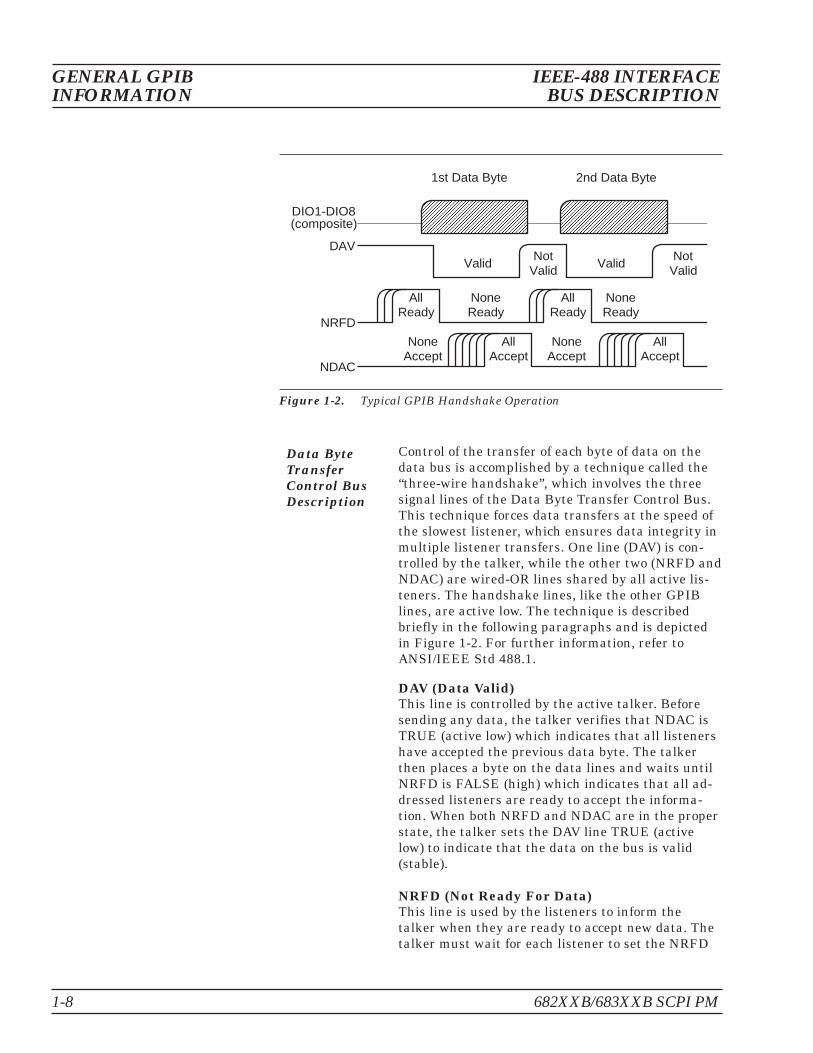


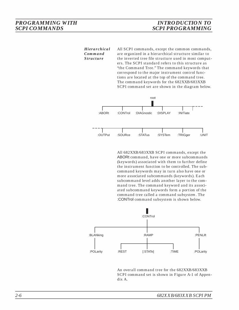


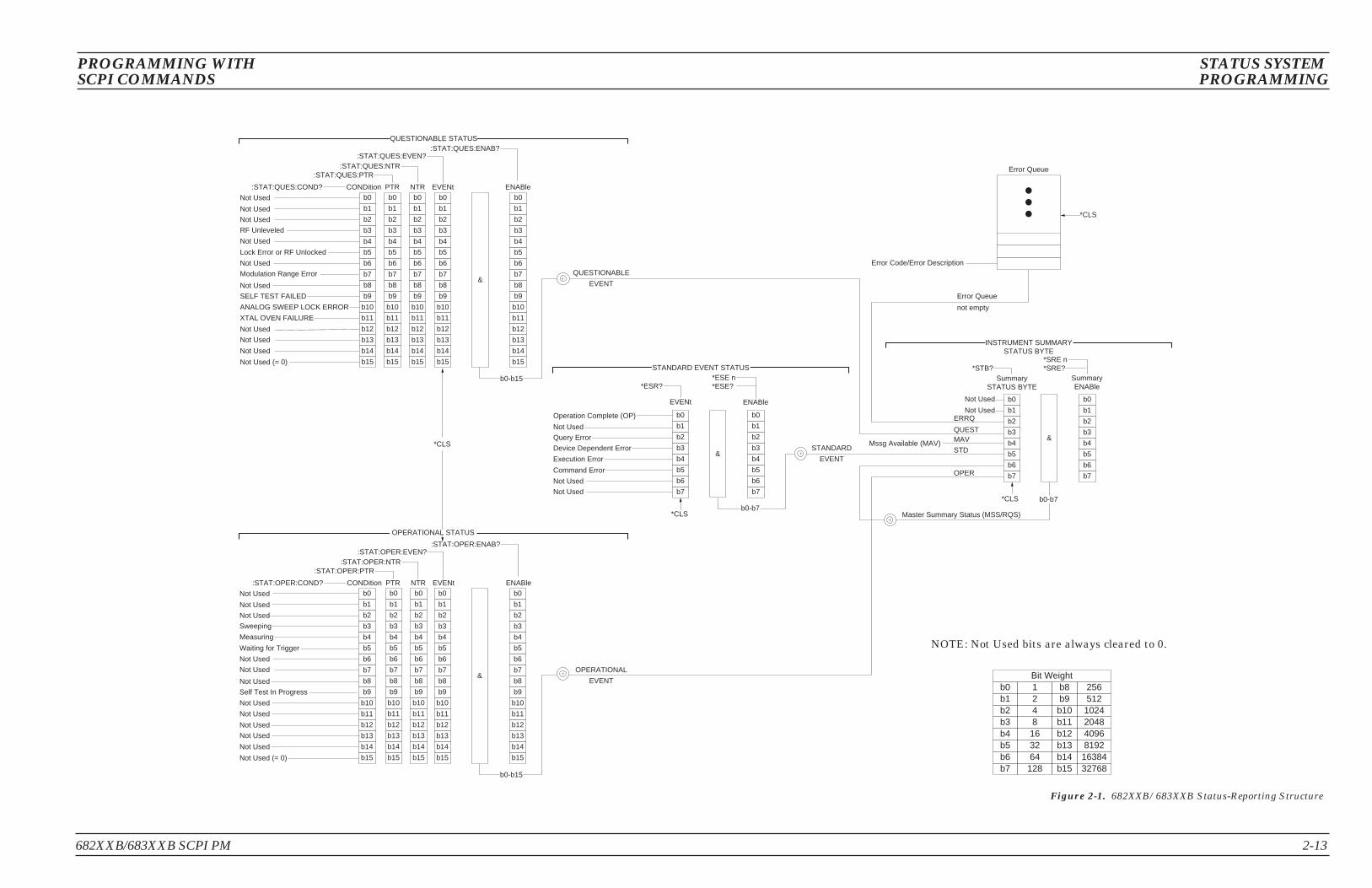


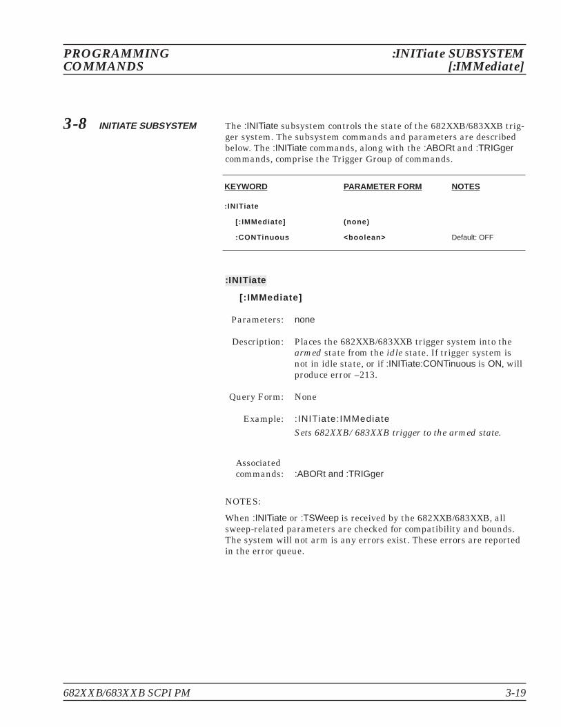


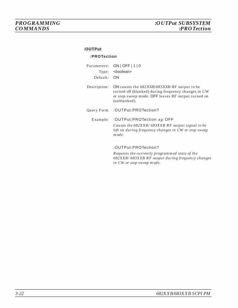
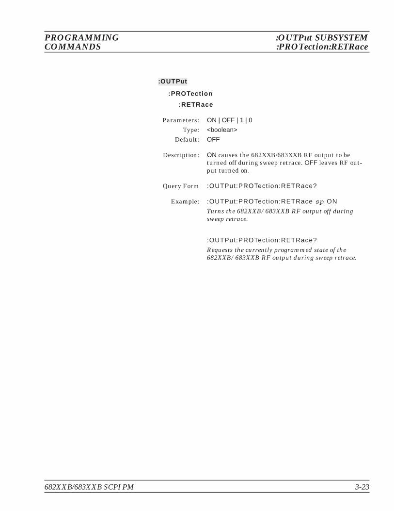


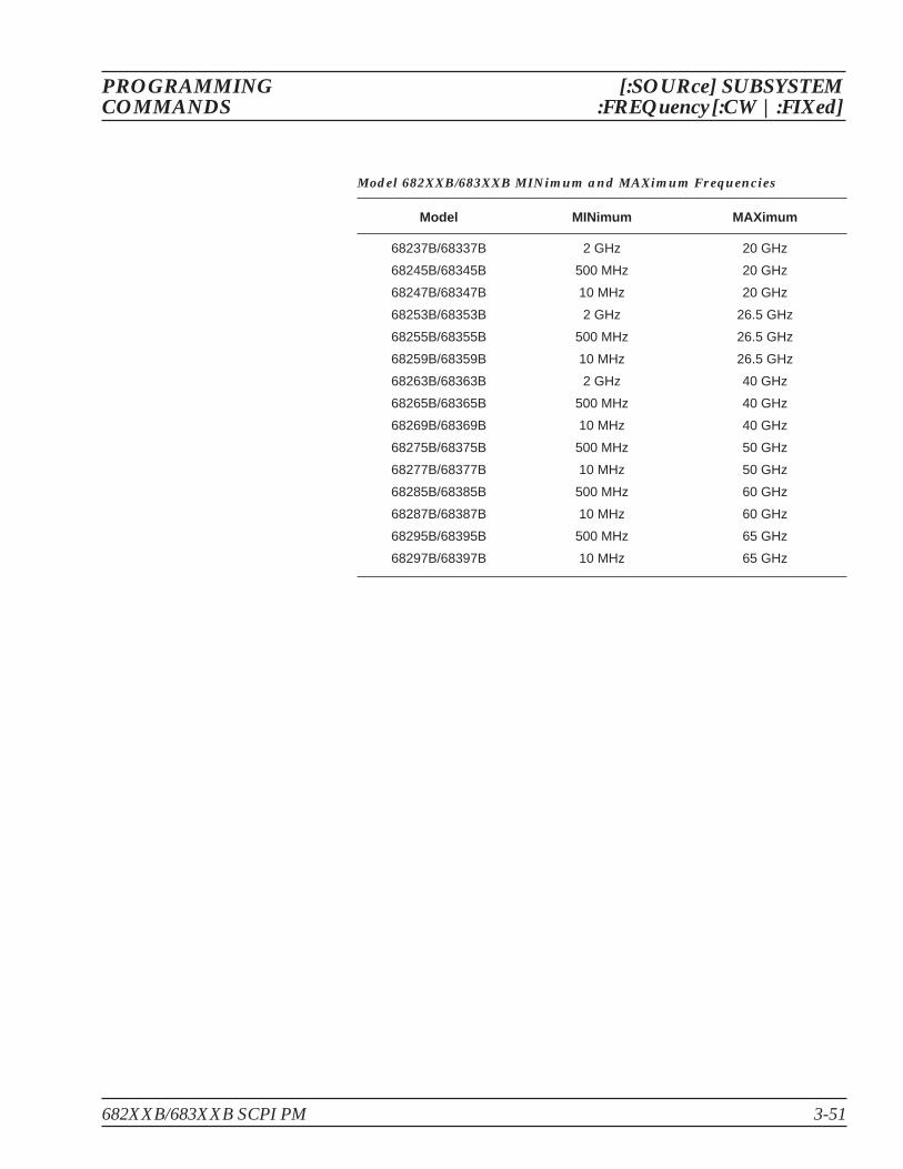


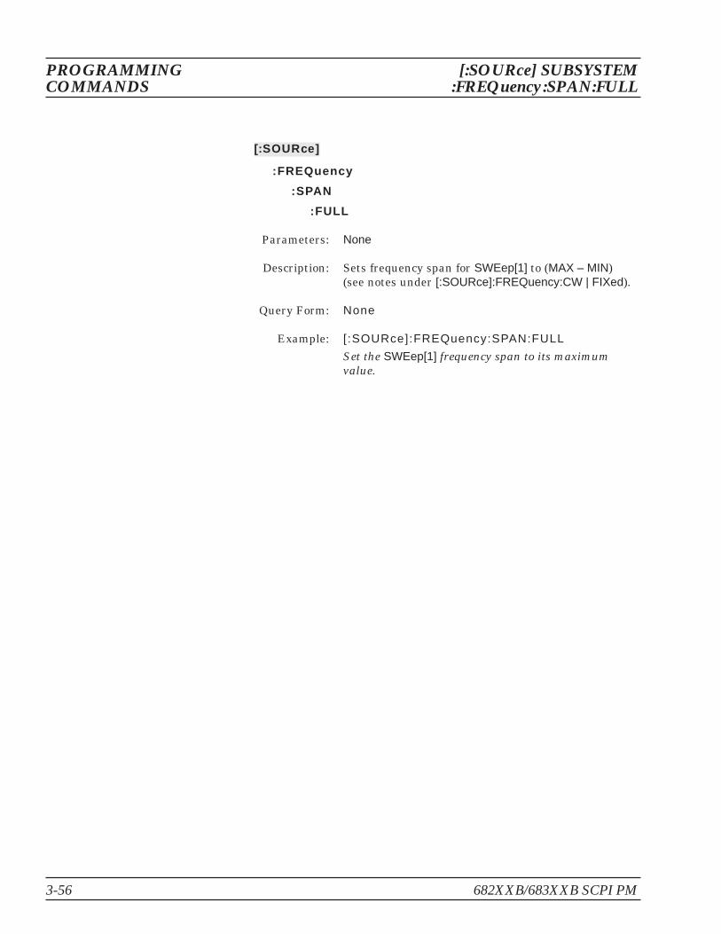


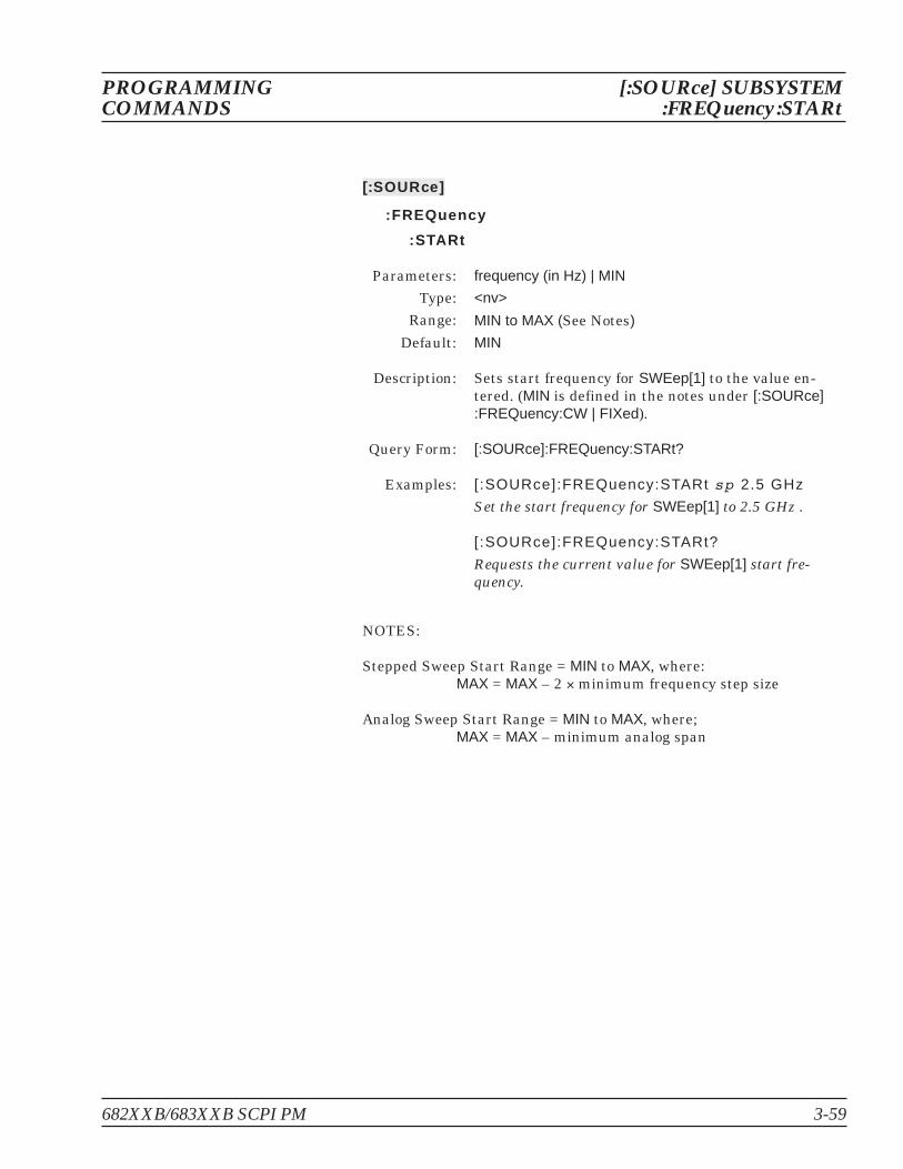


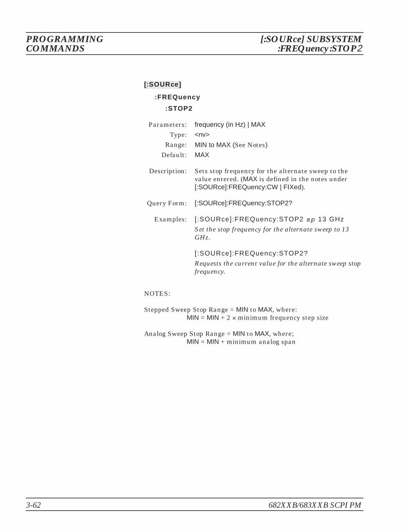


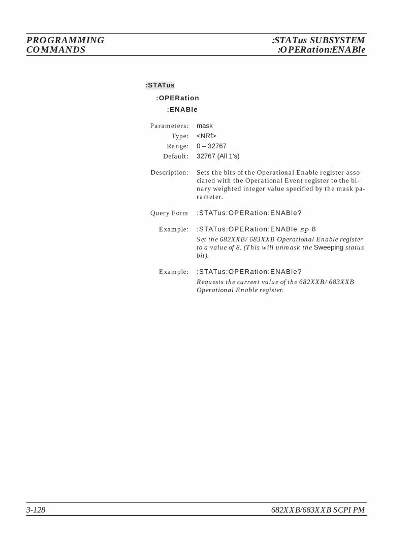


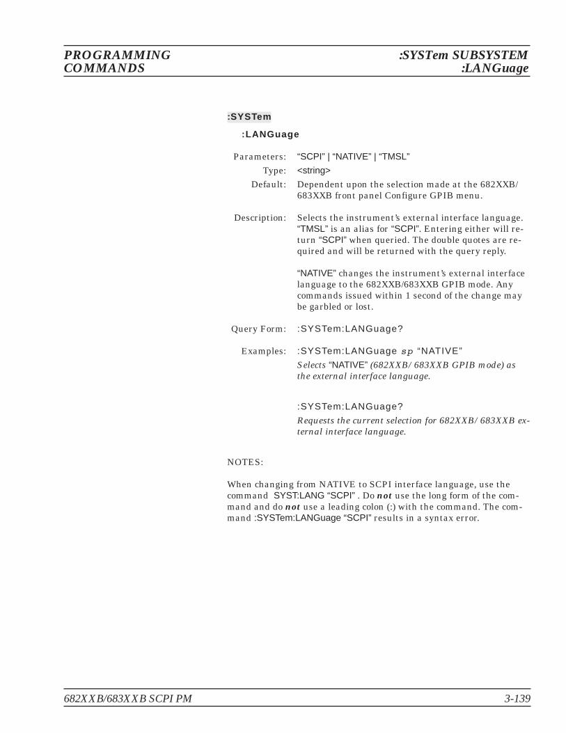


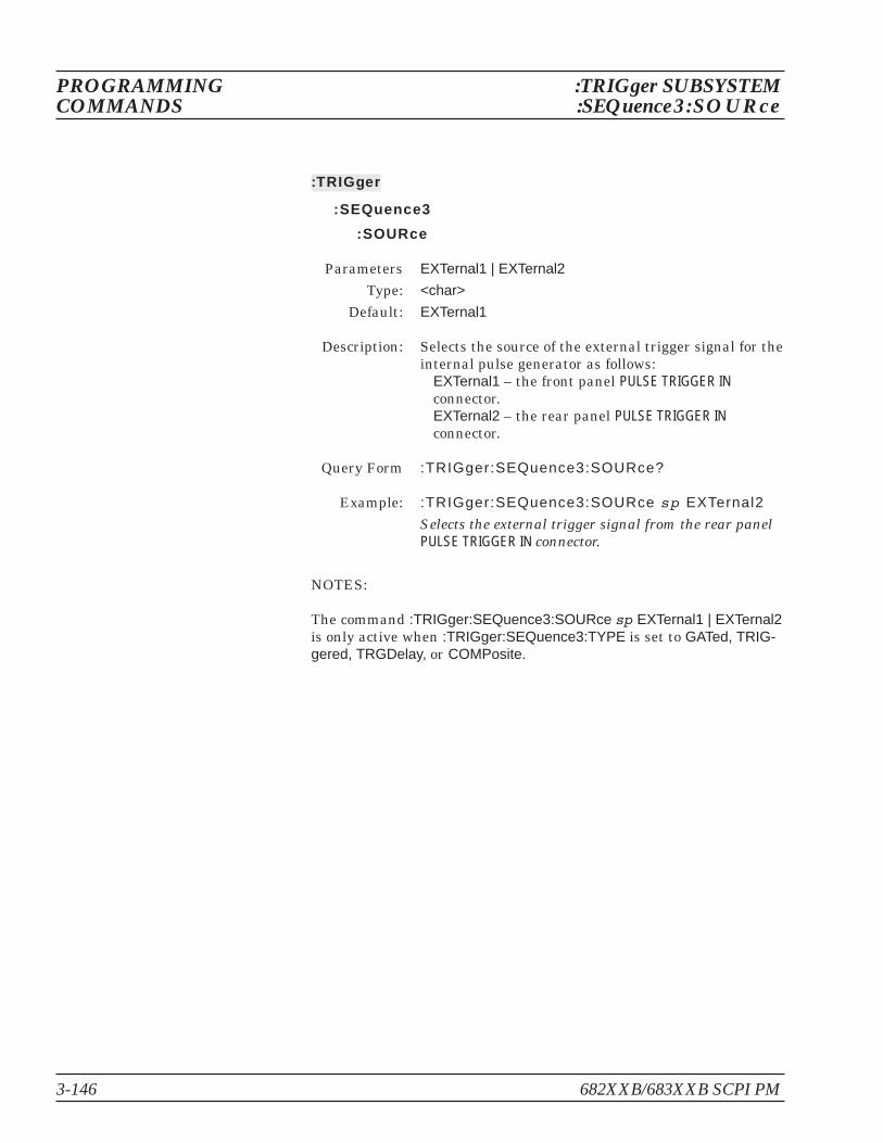


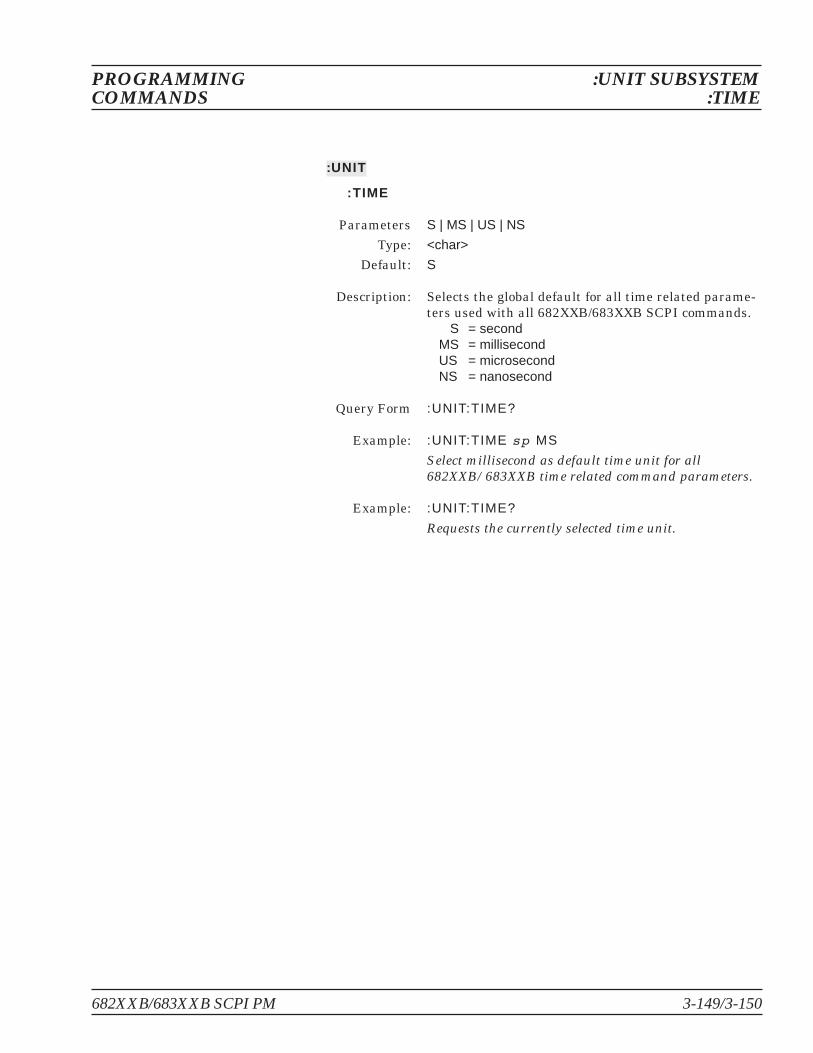


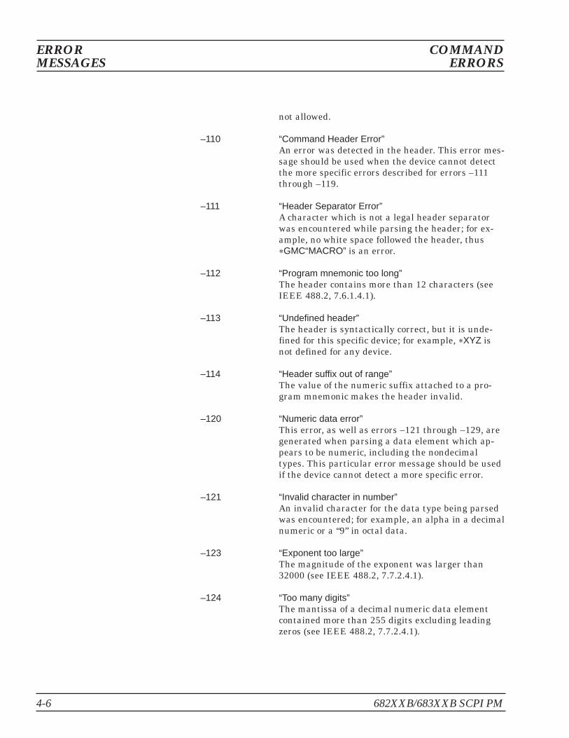


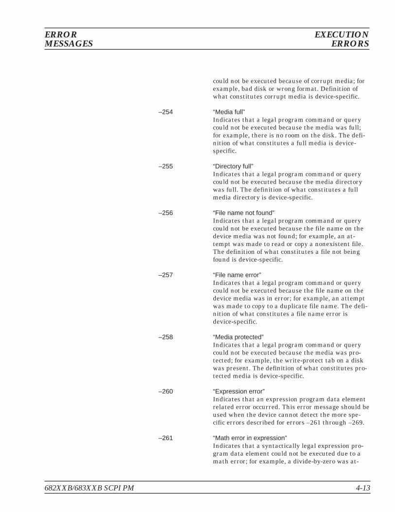


![[XLS] · Web viewRn.10731 AW140980 adenylyl cyclase RGIAX18 RGIAX20 RGIAX22 Rn.19577 AW142863 RGIAX24 Rn.10370 AW140984 glutamate decarboxylase RGIAZ14 X77953 RGIAZ16 RGIAZ18 Rn.16455](https://static.documents.pub/doc/80x56/5aa4a9887f8b9afa758c3648/xls-viewrn10731-aw140980-adenylyl-cyclase-rgiax18-rgiax20-rgiax22-rn19577-aw142863.jpg)


