6x8 MATRIX LED DRIVER Integrated Silicon Solution, Inc. – www.issi.com 1 Rev. C, 03/22/2017 DESCRIPTION The IS32FL3738 is an automotive grade general purpose 6×8 LEDs matrix driver with 1/12 cycle rate. The device can be programmed via an I2C compatible interface. Each LED can be dimmed individually with 8-bit × 4 PWM data which allowing 512 steps of linear dimming. IS32FL3738 features 3 Auto Breathing Modes which are noted as ABM-1, ABM-2 and ABM-3. For each Auto Breathing Mode, there are 4 timing characters which include current rising / holding / falling / off time and 3 loop characters which include Loop-Beginning / Loop-Ending / Loop-Times. Every LED can be configured to be any Auto Breathing Mode or No-Breathing Mode individually. FEATURES Up to 48 LEDs (6×8) in dot matrix Programmable 6×8 (16 RGBs) matrix size with de-ghost function Selectable 3 Auto Breath Modes for each dot Auto Breath Loop Features interrupt pin inform MCU Auto Breath Loop completed Auto Breath offers 128 steps gamma current, interrupt and state look up registers 256 steps Global Current Setting Individual 512 PWM control steps Individual Auto Breath Mode select Individual open and short error detect function QUICK START Figure 1: Photo of IS32FL3738 Evaluation Board (V01A board with 12V DC input please refer to AppendixⅠ) RECOMMENDED EQUIPMENT 5.0V, 2A Micro USB Arduino IDE, www.arduino.cc/en/Main/Software Arduino code download from ISSI website ABSOLUTE MAXIMUM RATINGS ≤ 5.5V Micro USB DC power supply Caution: Do not exceed the conditions listed above, otherwise the board will be damaged. PROCEDURE The IS32FL3738 evaluation board is fully assembled, tested and comes programmed with evaluation software. Follow the steps listed below to verify board operation. Caution: Do not turn on the power supply until all connections are completed. 1) Connect the 5VDC USB power to the Micro USB. 2) Press K1 to cycle through a display mode. EVALUATION BOARD OPERATION The IS32FL3738 evaluation board drives16 RGB LEDs located underneath the light dispersing filter. Every press of the K1 switch will cycle through one of the 8 pre-programmed lighting sequences below: 1) White LED 2) Rainbow bar 3) Red color breath 4) Green color breath 5) Blue color breath 6) Pink color breath 7) Yellow color breath 8) Cyan color breath Note: IS32FL3738 solely controls the FxLED function on the evaluation board. ORDERING INFORMATION Part No. Temperature Range Package IS32FL3738-ZLA3-EB -40°C to +125°C (Automotive) eTSSOP-28, Lead-free Table 1: Ordering Information For pricing, delivery, and ordering information, please contacts ISSI’s analog marketing team at [email protected]or (408) 969-6600.
Transcript
6x8 MATRIX LED DRIVER
Integrated Silicon Solution, Inc. – www.issi.com 1 Rev. C, 03/22/2017
DESCRIPTION
The IS32FL3738 is an automotive grade general purpose 6×8 LEDs matrix driver with 1/12 cycle rate. The device can be programmed via an I2C compatible interface. Each LED can be dimmed individually with 8-bit × 4 PWM data which allowing 512 steps of linear dimming.
IS32FL3738 features 3 Auto Breathing Modes which are noted as ABM-1, ABM-2 and ABM-3. For each Auto Breathing Mode, there are 4 timing characters which include current rising / holding / falling / off time and 3 loop characters which include Loop-Beginning / Loop-Ending / Loop-Times. Every LED can be configured to be any Auto Breathing Mode or No-Breathing Mode individually.
FEATURES
Up to 48 LEDs (6×8) in dot matrix Programmable 6×8 (16 RGBs) matrix size with
de-ghost function Selectable 3 Auto Breath Modes for each dot Auto Breath Loop Features interrupt pin inform
MCU Auto Breath Loop completed Auto Breath offers 128 steps gamma current,
interrupt and state look up registers 256 steps Global Current Setting Individual 512 PWM control steps Individual Auto Breath Mode select Individual open and short error detect function
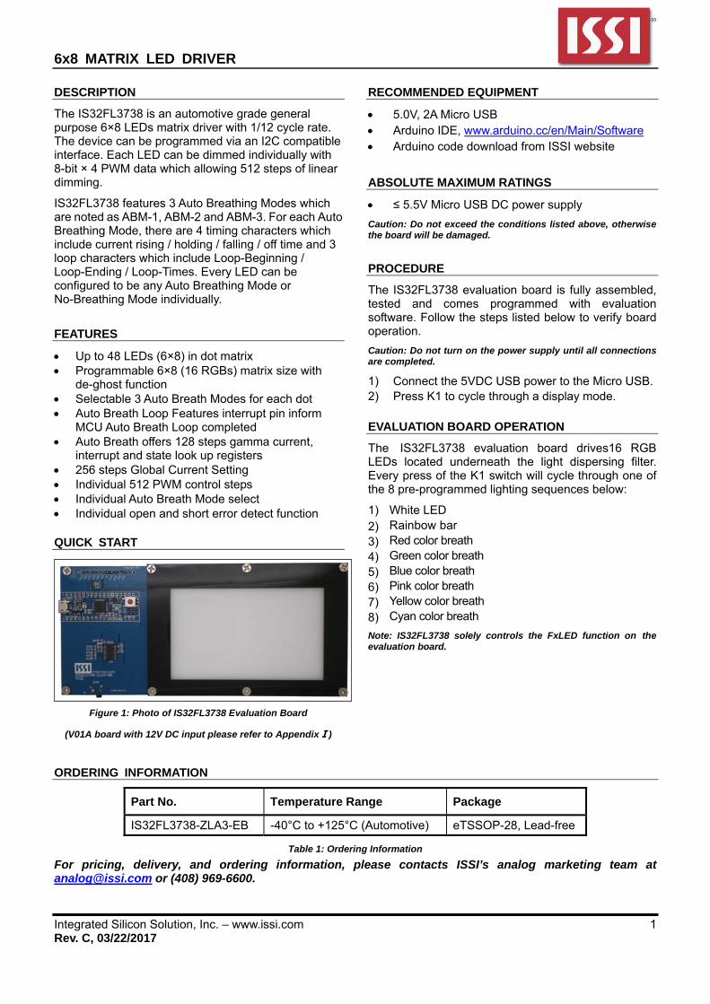
QUICK START
Figure 1: Photo of IS32FL3738 Evaluation Board
(V01A board with 12V DC input please refer to AppendixⅠ)
RECOMMENDED EQUIPMENT
5.0V, 2A Micro USB Arduino IDE, www.arduino.cc/en/Main/Software Arduino code download from ISSI website
ABSOLUTE MAXIMUM RATINGS
≤ 5.5V Micro USB DC power supply
Caution: Do not exceed the conditions listed above, otherwise the board will be damaged.
PROCEDURE
The IS32FL3738 evaluation board is fully assembled, tested and comes programmed with evaluation software. Follow the steps listed below to verify board operation.
Caution: Do not turn on the power supply until all connections are completed.
1) Connect the 5VDC USB power to the Micro USB. 2) Press K1 to cycle through a display mode. EVALUATION BOARD OPERATION
The IS32FL3738 evaluation board drives16 RGB LEDs located underneath the light dispersing filter. Every press of the K1 switch will cycle through one of the 8 pre-programmed lighting sequences below:
1) White LED 2) Rainbow bar 3) Red color breath 4) Green color breath 5) Blue color breath 6) Pink color breath 7) Yellow color breath 8) Cyan color breath
Note: IS32FL3738 solely controls the FxLED function on the evaluation board.
ORDERING INFORMATION
Part No. Temperature Range Package
IS32FL3738-ZLA3-EB -40°C to +125°C (Automotive) eTSSOP-28, Lead-free
Table 1: Ordering Information
For pricing, delivery, and ordering information, please contacts ISSI’s analog marketing team at [email protected] or (408) 969-6600.
6x8 MATRIX LED DRIVER
Integrated Silicon Solution, Inc. – www.issi.com 2 Rev. C, 03/22/2017
SOFTWARE CONTROL
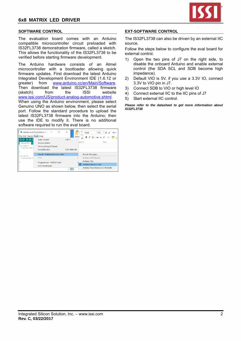
The evaluation board comes with an Arduino compatible microcontroller circuit preloaded with IS32FL3738 demonstration firmware, called a sketch. This allows the functionality of the IS32FL3738 to be verified before starting firmware development.
The Arduino hardware consists of an Atmel microcontroller with a bootloader allowing quick firmware updates. First download the latest Arduino Integrated Development Environment IDE (1.6.12 or greater) from www.arduino.cc/en/Main/Software. Then download the latest IS32FL3738 firmware (sketch) from the ISSI website www.issi.com/US/product-analog-automotive.shtml. When using the Arduino environment, please select Genuino UNO as shown below, then select the serial port. Follow the standard procedure to upload the latest IS32FL3738 firmware into the Arduino; then use the IDE to modify it. There is no additional software required to run the eval board.
EXT-SOFTWARE CONTROL
The IS32FL3738 can also be driven by an external IIC source.
Follow the steps below to configure the eval board for external control.
1) Open the two pins of J7 on the right side, to disable the onboard Arduino and enable external control (the SDA SCL and SDB become high impedance).
2) Default VIO is 5V, if you use a 3.3V IO, connect 3.3V to VIO pin in J7.
3) Connect SDB to VIO or high level IO 4) Connect external IIC to the IIC pins of J7 5) Start external IIC control.
Please refer to the datasheet to get more information about IS32FL3738
6x8 MATRIX LED DRIVER
Integrated Silicon Solution, Inc. – www.issi.com 3 Rev. C, 03/22/2017
Integrated Silicon Solution, Inc. – www.issi.com 7 Rev. C, 03/22/2017
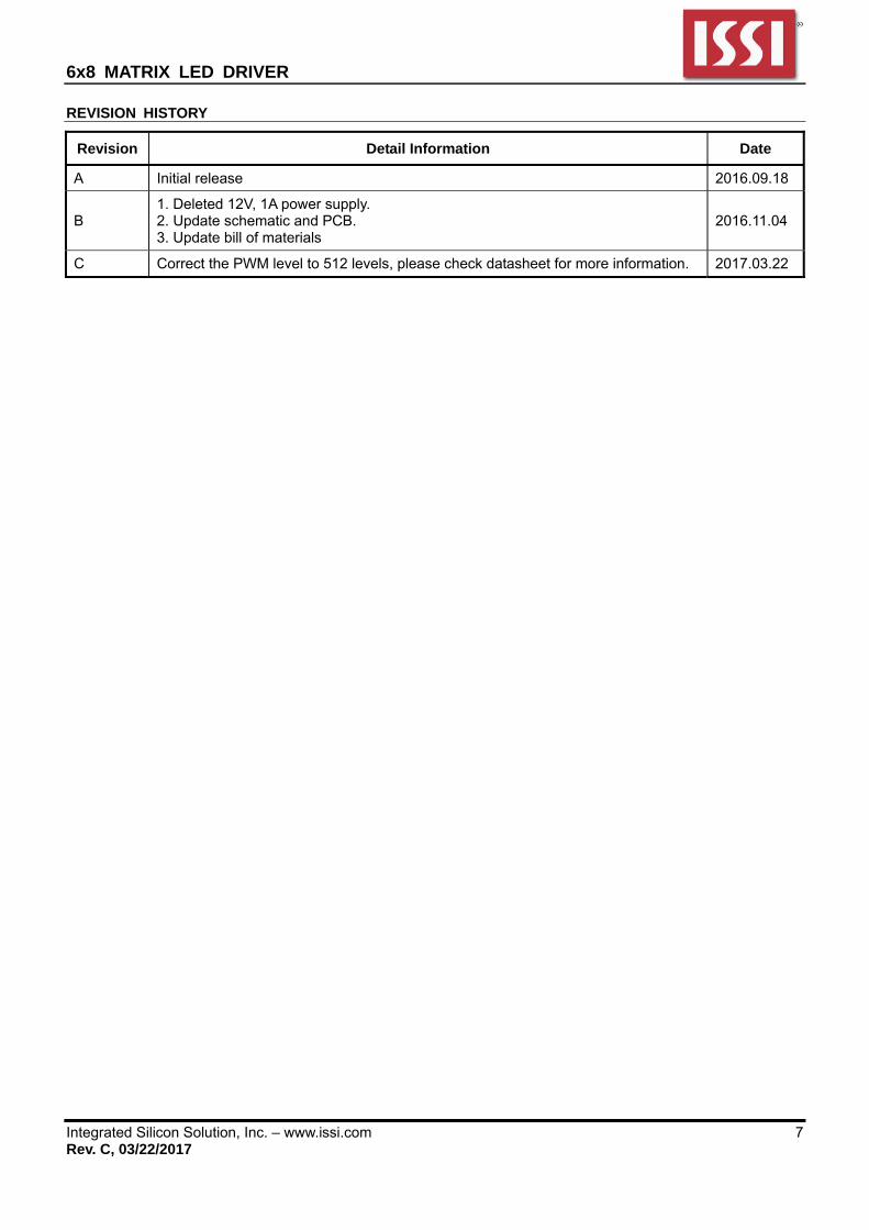
REVISION HISTORY
Revision Detail Information Date
A Initial release 2016.09.18
B 1. Deleted 12V, 1A power supply. 2. Update schematic and PCB. 3. Update bill of materials
2016.11.04
C Correct the PWM level to 512 levels, please check datasheet for more information. 2017.03.22
6x8 MATRIX LED DRIVER
Integrated Silicon Solution, Inc. – www.issi.com 8 Rev. C, 03/22/2017
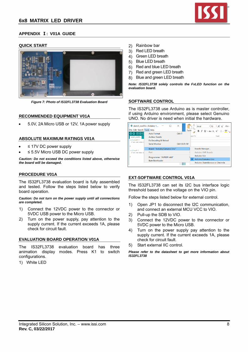
APPENDIX Ⅰ: V01A GUIDE
QUICK START
Figure 7: Photo of IS32FL3738 Evaluation Board
RECOMMENDED EQUIPMENT V01A
5.0V, 2A Micro USB or 12V, 1A power supply
ABSOLUTE MAXIMUM RATINGS V01A
≤ 17V DC power supply ≤ 5.5V Micro USB DC power supply
Caution: Do not exceed the conditions listed above, otherwise the board will be damaged.
PROCEDURE V01A
The IS32FL3738 evaluation board is fully assembled and tested. Follow the steps listed below to verify board operation.
Caution: Do not turn on the power supply until all connections are completed.
1) Connect the 12VDC power to the connector or 5VDC USB power to the Micro USB.
2) Turn on the power supply, pay attention to the supply current. If the current exceeds 1A, please check for circuit fault.
EVALUATION BOARD OPERATION V01A
The IS32FL3738 evaluation board has three animation display modes. Press K1 to switch configurations.
1) White LED
2) Rainbow bar 3) Red LED breath 4) Green LED breath 5) Blue LED breath 6) Red and blue LED breath 7) Red and green LED breath 8) Blue and green LED breath
Note: IS32FL3738 solely controls the FxLED function on the evaluation board.
SOFTWARE CONTROL
The IS32FL3738 use Arduino as is master controller, if using Arduino environment, please select Genuino UNO. No driver is need when initial the hardware.
EXT-SOFTWARE CONTROL V01A
The IS32FL3738 can set its I2C bus interface logic threshold based on the voltage on the VIO pin.
Follow the steps listed below for external control.
1) Open JP1 to disconnect the I2C communication, and connect an external MCU VCC to VIO.
2) Pull-up the SDB to VIO. 3) Connect the 12VDC power to the connector or
5VDC power to the Micro USB. 4) Turn on the power supply pay attention to the
supply current. If the current exceeds 1A, please check for circuit fault.
5) Start external IIC control.
Please refer to the datasheet to get more information about IS32FL3738
6x8 MATRIX LED DRIVER
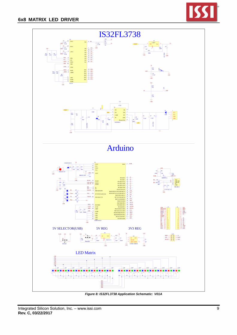
Integrated Silicon Solution, Inc. – www.issi.com 9 Rev. C, 03/22/2017