Knox County Tennessee Stormwater Management Manual Volume 2 (Technical Guidance) 7.3 Culvert Design A culvertis a short, closed (covered) conduit that conveys stormwater runoff under an embankment, usually a roadway. The primary purpose of a culvert is to convey surface water, but properly designed it may also be used to restrict flow and reduce downstream peak flows. In addition to the hydraulic function, a culvert must also support the embankment and/or roadway, and protect traffic and adjacent property owners from flood hazards to the extent practicable. Most culvert design is empirical and relies on nomographs and st andard procedures. The purpose of this section is to provide an overview of culvert design standards and procedures. 7.3.1 Symbols and Definitions To provide consistency within this section the symbols listed in Table 7-1 will be used. These symbols were selected because of their wide use. Table 7-1.Culvert Design Symbols and Definitions Symbol Definition Units A Area of cross section of flow ft 2 B Barrel width ft C d Overtopping discharge coefficient - D Culvert diameter or barrel width in or ft d Depth of flow ft d c Critical depth of flow ft d u Uniform depth of flow ft g Acceleration due to gravity ft/s 2 H fDepth of pool or head, above the face section of invert ft h o Height of hydraulic grade line above outlet invert ft HW Headwater depth above invert of culvert (depth from inlet to upstream total energy grade line) ft K e Inlet loss coefficient - L Length of culvert ft N Number of barrels - Q Rate of discharge cfs S Slope of culvert ft/ft TW Tailwater depth above invert of culvert ft V Mean velocity of flow ft/s V c Critical velocity ft/s 7.3.2 Design Standards and ConsiderationsThe design of a culvert should take into account many different engineering and technical aspects at the culvert site and adjacent areas. The list below presents the key considerations for the design of culverts. • Culverts can serve double duty as flow retarding structures in grass channel design. Care should be taken to design them as storage control structures if flow depths exceed several feet, and to ensure public safety. • Improved inlet designs can absorb considerable energy for steeper sloped and skewed inlet condition designs, thus helping to protect channels. All culverts designed and installed in Knox County shall conform to the design standards l isted in the following sections.
Knox County Tennessee Stormwater Management Manual
Volume 2 (Technical Guidance)
7.3 Culvert DesignA culvert is a short, closed (covered) conduit that conveys stormwater runoff under anembankment, usually a roadway. The primary purpose of a culvert is to convey surface water, butproperly designed it may also be used to restrict flow and reduce downstream peak flows. Inaddition to the hydraulic function, a culvert must also support the embankment and/or roadway,and protect traffic and adjacent property owners from flood hazards to the extent practicable.
Most culvert design is empirical and relies on nomographs and standard procedures. The purposeof this section is to provide an overview of culvert design standards and procedures.
7.3.1 Symbols and DefinitionsTo provide consistency within this section the symbols listed in Table 7-1 will be used. Thesesymbols were selected because of their wide use.
Table 7-1. Culvert Design Symbols and DefinitionsSymbol Definition Units
A Area of cross section of flow ft 2 B Barrel width ftCd Overtopping discharge coefficient -D Culvert diameter or barrel width in or ft
d Depth of flow ftdc Critical depth of flow ftdu Uniform depth of flow ftg Acceleration due to gravity ft/s 2
H f Depth of pool or head, above the face section of invert ftho Height of hydraulic grade line above outlet invert ft
HW Headwater depth above invert of culvert (depth from inletto upstream total energy grade line) ft
K e Inlet loss coefficient -L Length of culvert ftN Number of barrels -Q Rate of discharge cfsS Slope of culvert ft/ft
TW Tailwater depth above invert of culvert ftV Mean velocity of flow ft/s
Vc Critical velocity ft/s
7.3.2 Design Standards and ConsiderationsThe design of a culvert should take into account many different engineering and technical aspectsat the culvert site and adjacent areas. The list below presents the key considerations for thedesign of culverts.
• Culverts can serve double duty as flow retarding structures in grass channel design. Careshould be taken to design them as storage control structures if flow depths exceed severalfeet, and to ensure public safety.
• Improved inlet designs can absorb considerable energy for steeper sloped and skewed inletcondition designs, thus helping to protect channels.
All culverts designed and installed in Knox County shall conform to the design standards l isted inthe following sections.
Knox County Tennessee Stormwater Management Manual
Volume 2 (Technical Guidance) Page 1-2
The 25-year frequency storm shall be routed through all culverts and the 100-year storm shall beused as a check , to verify structures (e.g., houses, commercial buildings) are not flooded orincreased damage does not occur to the highway or adjacent property for this design event.
Both minimum and maximum velocities shall be considered when designing a culvert. Themaximum velocity shall be consistent with channel stability requirements at the culvert outlet. Themaximum allowable velocity is 15 feet per second. Outlet protection shall be provided wheredischarge velocities will cause erosion problems. To ensure self-cleaning during partial depth flow,culverts shall have a minimum velocity of 2.5 feet per second at design flow or lower, with aminimum slope of 0.5%.
Buoyancy protection shall be provided for all flexible culverts. This can be provided through theuse of headwalls, endwalls, slope paving or other means of anchoring.
The culvert length and slope shall be chosen to approximate existing topography. To the degree practicable,the culvert invert should be aligned with the channel bottom and the skew angle of the stream, and the culvertentrance should match the geometry of the roadway embankment .
! " #Debris control shall be performed in a manner consistent with Hydraulic Engineering Circular No. 9 entitled Debris Control Structures (FHWA, 1971), which contains criteria pertaining to the design ofdebris control structures.
$ % &Headwater is water above the culvert invert at the entrance end of the culvert. The allowableheadwater elevation is that elevation above which damage may be caused to adjacent propertyand/or the roadway. The headwater elevation is determined from an evaluation of land useupstream of the culvert and the proposed or existing roadway elevation. It is this allowableheadwater depth that is the primary basis for sizing a culvert.
The following criteria related to headwater should be considered when designing a culvert for the25-year design storm event.
• The allowable headwater is the depth of water that can be ponded at the upstream end of theculvert during the 100 yr event with clogged conditions, which will be limited by one or more ofthe following constraints or conditions.
(1) The allowable headwater must not damage upstream property.
(2) The ponding depth is to be no greater than the low point in the road grade.
(3) The ponding depth is to be no greater than the elevation where flow diverts around theculvert.
(4) Headwater elevations shall be established to delineate potential flood zones.
• In general, the constraint that gives the lowest allowable headwater elevation (HW) establishesthe criteria for the hydraulic calculations.
Knox County Tennessee Stormwater Management Manual
Volume 2 (Technical Guidance) Page 1-3
• For drainage facilities with cross-sectional area equal to or less than 30 ft 2, HW/D should beequal to or less than 1.5.
• For drainage facilities with cross-sectional area greater than 30 ft 2, HW/D should be equal to orless than 1.2.
• The headwater should be checked using the peak discharge for the 100-year frequency event(Qp 100 ) to ensure compliance with storm system design criteria. As well, the culvert should be
sized to maintain flood-free conditions on classified roadways.• The maximum acceptable outlet velocity shall be identified (see Section 7.4.3) in drainage
calculations included with the Stormwater Management Plan.
• Acceptable flow velocities shall be achieved by one of two ways: the headwater shall be set toan appropriate elevation; or, stabilization or energy dissipation shall be provided whereacceptable velocities are exceeded.
• Other site-specific design considerations shall be addressed as required by the Director.
' & #The hydraulic conditions downstream of the culvert site must be evaluated to determine a tailwaterdepth for a range of discharge. At times, there may be a need for calculating backwater curves toestablish the tailwater conditions. The following conditions must be considered when establishingtailwater conditions.
• If the culvert outlet is operating with a free outfall, the critical depth and equivalent hydraulicgrade line should be determined.
• For culverts that discharge to an open channel, the stage-discharge curve for the channel mustbe determined (see Section 7.4).
• If an upstream culvert outlet is located near a downstream culvert inlet, the headwaterelevation of the downstream culvert may establish the design tailwater depth for the upstreamculvert.
• If the culvert discharges to a lake, pond, or other major water body, the expected high waterelevation of the particular water body can be used to establish the culvert tailwater.
(If storage is being assumed or will occur upstream of the culvert, storage routing must be
performed in accordance with the information provided in Section 7.3.4.6.
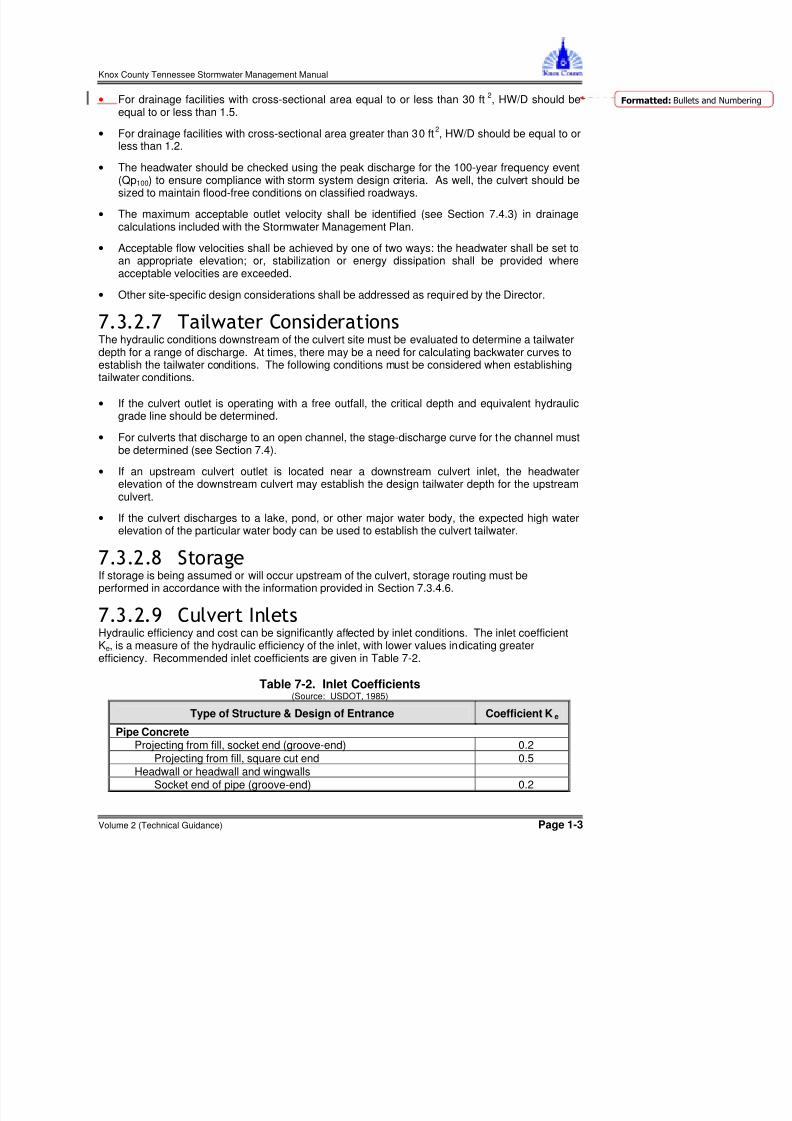
) # * +Hydraulic efficiency and cost can be significantly affected by inlet conditions. The inlet coefficientKe, is a measure of the hydraulic efficiency of the inlet, with lower values indicating greaterefficiency. Recommended inlet coefficients are given in Table 7-2.
Knox County Tennessee Stormwater Management Manual
Volume 2 (Technical Guidance) Page 1-4
Square-edge 0.5 Rounded [radius = 1/12(D)] 0.2
Mitered to conform to fill slope 0.7End-Section conforming to fill slope* 0.5 Beveled edges, 33.7 o or 45 o bevels 0.2 Side- or slope-tapered inlet 0.2
Pipe, or Pipe-Arch, Corrugated Metal 1
Projecting from fill (no headwall) 0.9 Headwall or headwall and wingwalls square-edge 0.5 Mitered to fill slope, paved or unpaved slope 0.7 End-Section conforming to fill slope* 0.5Beveled edges, 33.7 o or 45 o bevels 0.2Side- or slope-tapered inlet 0.2
Box, Reinforced ConcreteHeadwall parallel to embankment (no wingwalls)
Square-edged on 3 edges 0.5Rounded on 3 edges to radius of [1/12(D)] or beveled edges on3 sides
0.2
Wingwalls at 30 o to 75 o to barrelSquare-edged at crown 0.4Crown edge rounded to radius of [1/12(D)] or beveled top edge 0.2
Wingwalls at 10 o or 25 o to barrel
Square-edged at crown 0.5Side- or slope-tapered inlet 0.21 Although laboratory tests have not been completed on K e values for High-Density Polyethylene (HDPE) pipes,
the K e values for corrugated metal pipes are recommended for HDPE pipes.* Note: End Section conforming to fill slope, made of either metal or concrete, are the sections commonly available
from manufacturers. From limited hydraulic tests they are equivalent in operation to a headwall in both inlet andoutlet control.
, + with HeadwallsHeadwalls may be used for a variety of reasons, including increasing the efficiency of the inlet,providing embankment stability, providing embankment protection against erosion, providingprotection from buoyancy, and shortening the length of the required structure. Headwalls arerequired for all metal culverts and where buoyancy protection is necessary. If high headwaterdepths are to be encountered, or the approach velocity in the channel will cause scour, a shortchannel apron shall be provided at the toe of the headwall.
This apron should extend at least one pipe diameter upstream from the entrance, and the top of theapron should not protrude above the normal streambed elevation.
- &Wingwalls must be used where the side slopes of the channel adjacent to the entrance areunstable or where the culvert is skewed to the normal channel flow.
+ * +Where inlet conditions control the amount of flow that can pass through the culvert, improved inletscan greatly increase the hydraulic performance of the culvert.
.Reinforced concrete pipe (RCP) is recommended for use (1) under a roadway, (2) when pipeslopes are less than 1%, or (3) for all flowing streams. RCP must be used for culverts designed for
a 100-year storm, if the culverts lie in public lands or easements.
Knox County Tennessee Stormwater Management Manual
Volume 2 (Technical Guidance) Page 1-5
RCP and fully coated corrugated metal pipe can be used in all other cases. High-densitypolyethylene (HDPE) pipe may also be used where permitted by the Director. Table 7-3 givesrecommended Manning’s “n” values for different materials.
Corrugated Metal 2-2/3- by ½-inch corrugations 0.024Pipes and Boxes 6- by 1-inch corrugations 0.025Annular 5- by 1-inch corrugations 0.026Corregations 3- by 1-inch corrugations 0.028
6-by 2-inch structural plate 0.0359-by 2-1/2 inch structural plate 0.035
Corrugated Metal 2-2/3-by ½-inch corrugated 24-inch plate 0.012Pipes, Helical width
Corrugations, FullCircular FlowSpiral Rib Metal Pipe 3/4 by 3/4 in recesses at 12 inch spacing, 0.013
good jointsHigh Density Corrugated Smooth Liner 0.015Polyethylene (HDPE) Corrugated 0.020Polyvinyl Chloride 0.011(PVC)Note: For further information concerning Manning “n” values for selected conduits consult Hydraulic Design ofHighway Culverts, Federal Highway Administration, HDS No. 5, page 163
# * / &Culvert skews shall not exceed 45 degrees as measured from a line perpendicular to the roadway
$ - %Weep holes are sometimes used to relieve uplift pressure. Filter materials shall be used inconjunction with the weep holes in order to intercept the flow and prevent the formation of pipingchannels. The filter materials shall be designed as an underdrain filter so as not to becomeclogged and so that piping cannot occur through the pervious material and the weep hole.
1Water shall not discharge from a culvert in an erosive manner. Outlet protection shall be providedfor all design storms. See Section 7.5 for information on the design of outlet protection.
Knox County Tennessee Stormwater Management Manual
Volume 2 (Technical Guidance) Page 1-6
( 2 * #Where compatible with good hydraulic engineering, a site should be selected that will permit theculvert to be constructed to cause the least impact on the stream, wetlands and otherenvironmentally sensitive features that may be located on the site. This selection must considerthe entire site, including any necessary lead channels.
7.3.3 Design Procedures
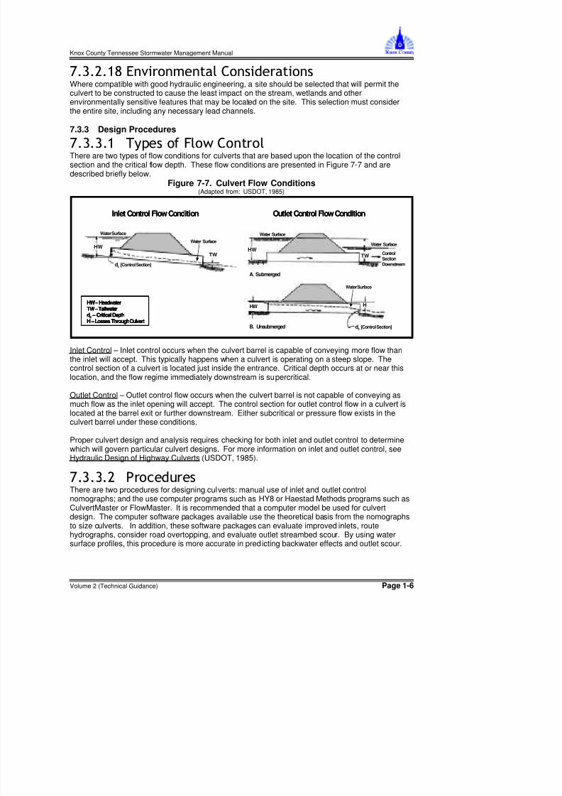
' 3 & #There are two types of flow conditions for culverts that are based upon the location of the controlsection and the critical flow depth. These flow conditions are presented in Figure 7-7 and aredescribed briefly below.
Inlet Control – Inlet control occurs when the culvert barrel is capable of conveying more flow thanthe inlet will accept. This typically happens when a culvert is operating on a steep slope. Thecontrol section of a culvert is located just inside the entrance. Critical depth occurs at or near thislocation, and the flow regime immediately downstream is supercritical.
Outlet Control – Outlet control flow occurs when the culvert barrel is not capable of conveying asmuch flow as the inlet opening will accept. The control section for outlet control flow in a culvert islocated at the barrel exit or further downstream. Either subcritical or pressure flow exists in theculvert barrel under these conditions.
Proper culvert design and analysis requires checking for both inlet and outlet control to determinewhich will govern particular culvert designs. For more information on inlet and outlet control, seeHydraulic Design of Highway Culverts (USDOT, 1985).
There are two procedures for designing culverts: manual use of inlet and outlet controlnomographs; and the use computer programs such as HY8 or Haestad Methods programs such asCulvertMaster or FlowMaster. It is recommended that a computer model be used for culvertdesign. The computer software packages available use the theoretical basis from the nomographsto size culverts. In addition, these software packages can evaluate improved inlets, routehydrographs, consider road overtopping, and evaluate outlet streambed scour. By using watersurface profiles, this procedure is more accurate in predicting backwater effects and outlet scour.
HW
Water Surface
Water Surface
TW
dc [Control Section]
HW – HeadwaterTW –Tailwaterdc – Critical DepthH –Losses Through Culvert
HW
HW
Water Surface
Water Surface
Water Surface
H
TW
dc [Control Section]
ControlSectionDownstream
A. Submerged
B. Unsubmerged
Inlet Control Flow Condition Outlet Control Flow Condition
HW
Water Surface
Water Surface
TW
dc [Control Section]
HW
Water Surface
Water Surface
TW
dc [Control Section]
HW – HeadwaterTW –Tailwaterdc – Critical DepthH –Losses Through Culvert
HW – HeadwaterTW –Tailwaterdc – Critical DepthH –Losses Through Culvert
HW
HW
Water Surface
Water Surface
Water Surface
H
TW
dc [Control Section]
ControlSectionDownstream
A. Submerged
B. Unsubmerged
HW
HW
Water Surface
Water Surface
Water Surface
H
TW
dc [Control Section]
ControlSectionDownstream
A. Submerged
B. Unsubmerged
Inlet Control Flow Condition Outlet Control Flow Condition
Knox County Tennessee Stormwater Management Manual
Volume 2 (Technical Guidance) Page 1-7
4The use of culvert design nomographs requires a trial and error solution. Nomograph solutionsprovide reliable designs for many applications. It should be remembered that velocity, hydrographrouting, roadway overtopping, and outlet scour require additional, separate computations beyondwhat can be obtained from the nomographs. Figures 7-8(a) and (b) show examples of an inletcontrol and outlet control nomograph for the design of concrete pipe culverts. For other culvertdesigns, refer to the complete set of nomographs in Appendix A.
!The following design procedure requires the use of inlet and outlet nomographs.
(Step 1) List design data:Q = discharge (cfs) L = culvert length (ft)S = culvert slope (ft/ft) TW= tailwater depth (ft)V = velocity for trial diameter (ft/s) K e = inlet loss coefficientHW= allowable headwater depth for the design storm (ft) D = pipe diameter (in)
(Step 2) Determine trial culvert size by assuming a trial velocity 5 to 8 ft/s and computing theculvert area, A = Q/V. Determine the culvert diameter.
(Step 3) Find the actual HW for the trial size culvert for both inlet and outlet control.
• For inlet control, enter inlet control nomograph with D and Q and find HW/D for the properentrance type.
• Compute HW and, if too large or too small, try another culvert size before computing HW foroutlet control.
• For outlet control enter the outlet control nomograph with the culvert length, entrance losscoefficient, and trial culvert diameter.
• To compute HW, connect the length scale for the type of entrance condition and culvertdiameter scale with a straight line, pivot on the turning line, and draw a straight line from thedesign discharge through the turning point to the head loss scale H. Compute the headwaterelevation HW from Equation 7-10.
Equation 7-10 LSh H HW o−=
where: H =head loss, ftho = ½(critical depth + D) or tailwater depth, whichever is greater (maximum = D)L = culvert lengthS = culvert slope
Knox County Tennessee Stormwater Management Manual
Volume 2 (Technical Guidance) Page 1-10
(Step 4) Compare the computed headwaters and use the higher HW nomograph to determine if the culvertis under inlet or outlet control.
• If inlet control governs, then the design is complete and no further analysis isrequired.
• If outlet control governs and the HW is unacceptable, select a larger trial size and findanother HW with the outlet control nomographs. Since the smaller size of culvert had been
selected for allowable HW by the inlet control nomographs, the inlet control for the largerpipe need not be checked.
(Step 5) Calculate exit velocity and if erosion problems might be expected, refer to Section 7.5 forappropriate energy dissipation designs.
3 # * 5 6 & 1*A performance curve for any culvert can be obtained from the nomographs by repeating the stepsoutlined above for a range of discharges that are of interest for that particular culvert design. Agraph is then plotted of headwater versus discharge with sufficient points so that a curve can bedrawn through the range of interest. These curves are applicable through a range of headwaterdepths and velocities versus discharges for specific lengths and types of culvert. Suchcomputations are made much easier by the use of computer programs.
To complete the culvert design, roadway overtopping must be analyzed. A performance curveshowing the culvert flow as well as the flow across the roadway is a useful analysis tool. Ratherthan using a trial and error procedure to determine the flow division between the overtopping flowand the culvert flow, an overall performance curve can be developed.
The overall performance curve can be determined using the following general procedure.
(Step 1) Select a range of flow rates and determine the corresponding headwater elevations for the culvertflow alone. The flow rates should fall above and below the design discharge and cover the entireflow range of interest. Both inlet and outlet control headwaters should be calculated.
(Step 2) Combine the inlet and outlet control performance curves to define a single performance curve forthe culvert.
(Step 3) When the culvert headwater elevations exceed the roadway crest elevation, overtopping willbegin. Calculate the equivalent upstream water surface depth above the roadway (crest of weir)for each selected flow rate. Use these water surface depths and equation 7-11 to calculate flowrates across the roadway.
Equation 7-11 ( ) 5.1 HW LC Q d =
where: Q = overtopping flow rate (cfs)Cd = overtopping discharge coefficientL = length of roadway (ft)HW = upstream depth, measured from the roadway crest to the water surface up-stream of
the weir drawdown (ft)
Note: See Figure 7-9 for guidance in determining a value for C d. For more information oncalculating overtopping flow rates see pages 38 - 40 in the Hydraulic Design of HighwayCulverts (USDOT, 1985).
(Step 4) Add the culvert flow and the roadway overtopping flow at the corresponding headwater elevationsto obtain the overall culvert performance curve.
Knox County Tennessee Stormwater Management Manual
Volume 2 (Technical Guidance) Page 1-11
Figure 7-9. Discharge Coefficients for Roadway Overtopping(Source: USDOT, 1985)
$ 6A significant storage capacity behind a highway embankment attenuates a flood hydrograph.Because of the reduction of the peak discharge associated with this attenuation, the requiredcapacity of the culvert, and its size, may be reduced considerably. If significant storage isanticipated behind a culvert, the design should be checked by routing the design hydrographsthrough the culvert to determine the discharge and stage behind the culvert. See Section 7.3.7 andVolume 2, Chapter 3, Section 3.2 for more information on routing. Additional routing proceduresare outlined in Hydraulic Design of Highway Culverts (USDOT, 1985).
Note: Storage should be taken into consideration only if the storage area will remain available for the life of the culvert as a result of purchase of ownership or right-of-way or an easement has been acquired.
7.3.5 Design Procedures for Beveled-Edged InletsImproved inlets include inlet geometry refinements beyond those normally used in conventionalculvert design practice. Several degrees of improvements are possible, including bevel-edged,side-tapered, and slope-tapered inlets. Those designers interested in using side- and slope-tapered inlets should consult the detailed design criteria and example designs outlined in theHydraulic Design of Highway Culverts (USDOT, 1985).
!Four inlet control figures for culverts with beveled edges are included in Appendix A.
Chart Use for :3 circular pipe culverts with beveled rings9 wingwalls with flare angles of 18 to 45 degrees10 90 o headwalls (same for 90 o wingwalls)11 skewed headwalls
The following symbols are used in Figure 7-10:
B - width of culvert barrel or diameter of pipe culvert;D - height of box culvert or diameter of pipe culvert;H - depth of pool or head, above the face section of invert;N - number of barrels; and,Q - design discharge.
Knox County Tennessee Stormwater Management Manual
Volume 2 (Technical Guidance) Page 1-15
!The figures (Appendix A) for bevel-edged inlets are used for design in the same manner as theconventional inlet design nomographs discussed earlier.
For box culverts the dimensions of the bevels to be used are based on the culvert dimensions. Thetop bevel dimension is determined by multiplying the height of the culvert by a factor. The sidebevel dimensions are determined by multiplying the width of the culvert by a factor. For a 1:1
bevel, the factor is 0.5 inch/ft. For a 1.5:1 bevel the factor is 1 inch/ft. For example, the minimumbevel dimensions for an 8 ft x 6 ft box culvert with 1:1 bevels would be:
Top Bevel = d = 6 ft x 0.5 inch/ft = 3 inches; and,Side Bevel = b = 8 ft x 0.5 inch/ft = 4 inches.
For a 1.5:1 bevel, the dimension computations would result in d = 6 and b = 8 inches.
!The improved inlet design figures (Appendix A) are based on research results from culvert modelswith barrel width, B, to depth, D, ratios of 0.5:1 to 2:1. For box culverts with more than one barrel,the figures are used in the same manner as for a single barrel, except that the bevels must besized on the basis of the total clear opening rather than on individual barrel size. For example, in adouble 8 ft by 8 ft box culvert:
The top bevel is proportioned based on the height of 8 feet which results in a bevel of 4 in. forthe 1:1 bevel and 8 in. for the 1.5:1 bevel.
The side bevel is proportioned based on the clear width of 16 feet, which results in a bevel of8 in. for the 1:1 bevel and 16 in. for the 1.5:1 bevel.
. 5" +For multi-barrel culvert installations exceeding a 3:1 width to depth ratio, the side bevels becomeexcessively large when proportioned on the basis of the total clear width. For these structures, it isrecommended that the side bevel be sized in proportion to the total clear width, B, or three timesthe height, whichever is smaller.
The top bevel dimension should always be based on the culvert height.
The shape of the upstream edge of the intermediate walls of multi-barrel installations is not asimportant to the hydraulic performance of a culvert as the edge condition of the top and sides.Therefore, the edges of these walls may be square, rounded with a radius of one-half theirthickness, chamfered, or beveled. The intermediate walls may also project from the face and slopedownward to the channel bottom to help direct debris through the culvert.
Multi-barrel pipe culverts shall be designed as a series of single barrel installations since each piperequires a separate bevel.
/ & +It is recommended that Chart 11 for skewed inlets (Appendix A) not be used for multiple barrelinstallations, as the intermediate wall could cause an extreme contraction in the downstreambarrels. This would result in under design due to a greatly reduced capacity. Skewed inlets (at anangle with the centerline of the stream) should be avoided whenever possible and should not beused with side- or slope-tapered inlets. It is important to align culverts with streams in order toavoid erosion problems associated with changing the direction of the natural stream flow.
Knox County Tennessee Stormwater Management Manual
Volume 2 (Technical Guidance) Page 1-16
7.3.6 Flood Routing and Culvert DesignFlood routing through a culvert is a practice that evaluates the effect of temporary upstreamponding caused by the culvert's backwater. If flood routing is not considered, it is possible that thefindings from culvert analyses will be conservative. If the selected allowable headwater is acceptedwithout flood routing, then costly over design of both the culvert and outlet protection may result,depending on the amount of temporary storage involved. However, if storage is used in the designof culverts, consideration should be given to:
• the total area of flooding,
• the average time that bankfull stage is exceeded for the design flood up to 48 hours in ruralareas or 6 hours in urban areas, and
• ensuring that the storage area will remain available for the life of the culvert through thepurchase of right-of-way or easement.
$ !The design procedure for flood routing through a culvert is the same as for reservoir routing. Thesite data and roadway geometry are obtained and the hydrology analysis completed to includeestimating a hydrograph. Once this essential information is available, the culvert can be designed.Flood routing through a culvert can be time consuming. It is recommended that a computerprogram be used to perform routing calculations; however, an engineer should be familiar with theculvert flood routing design process.
A multiple trial and error procedure is required for culvert flood routing as presented in the generaldesign steps listed below.
(Step 1) A trial culvert(s) is selected.
(Step 2) A trial discharge for a particular hydrograph time increment (selected time increment toestimate discharge from the design hydrograph) is selected.
(Step 3) Flood routing computations are made with successive trial discharges until the floodrouting equation is satisfied.
(Step 4) The hydraulic findings are compared to the selected site criteria.
(Step 5) If the selected site criteria are satisfied, then a trial discharge for the next time increment
is selected and this procedure is repeated; if not, a new trial culvert is selected and theentire procedure is repeated.