7 AD-A128 698 A MATHEMATICAL MODEL FOR THE VERIFICATION OF SYSTOLIC i/i NETWORKS(U) PITTSBURGH UNIV PA INST FOR COMPUTATIONAL MATHEMATICS AND RPP. . R G MELNEM ET AL. OCT 82 UNCLASSIFIED ICHR-82-47 NOBOi4-BS-C-8455 .F/G 12/1 N smmohmohhosi smmhhhhhhohmhh EhhhhhhhhhhhhI smhhhmhhhhhhh
Transcript
7AD-A128 698 A MATHEMATICAL MODEL FOR THE VERIFICATION OF SYSTOLIC i/i
NETWORKS(U) PITTSBURGH UNIV PA INST FOR COMPUTATIONALMATHEMATICS AND RPP. . R G MELNEM ET AL. OCT 82
UNCLASSIFIED ICHR-82-47 NOBOi4-BS-C-8455 .F/G 12/1 N
INSTITUTE FOR COMPUTATIONALMATHEMATICS AND APPLICATIONS
L Dpartment of Mathematics and Statistics
L University of Pittsburgh
L 0, T 3 2'1a2
c~ beelL?
- 82 10 25 021
--4 77----- - ---
p. 45 lin +8: cooe.n , epciey
Technical Report ICMA-82-47
A MATHEMATICAL MODEL FOR THE VERIFICATION
OF SYSTOLIC NETWORKS 1
Rami G. MelhemDepartment of Computer Science
andDepartment of Mathematics and Statistics
andWerner C. Rheinboldt
Department of Mathematics and Statistics
F"
7.,
1) This work was supported in part by the Office of Naval Research underContract N0014-80-C-0455 and the U.S. Air Force Office of ScientificResearch under Grant 80-0176.
4
ir
0 •"ABSTRACTJ,
A mathematical model for systolic architectures is sug-
gested and used to verify the operation of certain systolic
networks. The data items appearing on the communication
links of such a network at successive time units are
represented by data sequences and the computations performed
by the network-cells are modeled by a system of difference
* equations involving operations on the various data
sequences. The input/output descriptions, which describe
the global effect of the computations performed by the net-
work, are obtained by solving this system of difference
equations. This input/output description can then be used
to verify the operation of the network. The suggested
verification technique is applied to four different systolic
networks proposed in the literature.
-. '
"",f-
-2-
. ,- Introduction.
Systolic architectures, pioneered by H. T. Kung, are
becoming increasingly attractive due to continuous advances
in VLESI technology. This type of network architectures has
two properties very desirable in VLSI implementations;
namely, regularity and the local nature of the interconnec-
tions.
A systolic network can be viewed as a network composed
* of a few types of computational cells, regularly intercon-
nected via local data links and organized such that streams
of data flow smoothly within the network. For an introduc-
tion to systolic architectures, we refer to (10] where
further references to specific examples are given.
As an introductory example, wp briefly review a simple
systolic network for the computation of one dimensional con-
volution expressions [10]. More specifically, given a
sequence of numbers (xI, x 2 , ... , and a sequence of
weights (w1 , w2 , ... wk, we want to compute the sequence
(YI' Y2 ' Yn+l-k where each yi is defined by:
kY W wj xi+_ 1 . (1.1)
Figure 1 shows the building cell of the 1-D convolution
network under discussion. It is a multiply/add cell with a
*: . one word memory to store a real number w.
-3-
xiXn 0 X3 XX
w3 w2 w
Figure ()Figure (2)
x3-x2 x32 W2V
0t* 3
t -4
t 5
V.+ W 3 x 3
Figure (3)
F
-4-
At each clock pulse, the cell receives two input data items;
Xin and Yin ' performs its computation and delivers at the
next clock pulse the outputs x 0 W Xin and
Y Yin + w 'in- Figure 2 shows three such cells con-
nected into a network that performs the convolution calcula-
* tion for the case k-3. The elements x1 , x2 , ... xn are
*pumped in at the left end of the network, each separated
from the other by one time unit, and zeroes are pumped inAt
the right end. To illustrate the operation of the array, we
show in figure 3 the relative location and value of each
data item at times t-3,4,5 and 6, where t-l is the time at
which the array started its execution. By following the data
paths, we can convince ourselves that the output of the
* array will include the sequence (yl, y2 , .. Yn+l-k
*Although the concept of systolic networks is very well
developed, the notation used to describe the input and out-
put data of a systolic network is sometimes ambiguous and
reflects poorly the relative timing of the different data
streams. Moreover, no rigorous techniques appear to be
known for a formal verification of the operation of such
networks. To the knowledge of the authors, there has been
only one attempt (6] to verify formally the operation of
systolic networks based on a proof technique used in the
verification of distributed systems (4]. This technique
does not make use of the special properties of systolic net-
works and hence gives only rather general results.
In this paper, we suggest a technique designed specifi-
cally for verifying the operation of systolic networks. In
section 2.1 the data sequences are introduced to represent
the data appearing on the communication links at successive
time intervals. In the same section, we discuss the causal
operators which model the computations performed by a cell
of the network. This concept was primarily inspired by
corresponding approaches in systems theory [7].
In section 2.2 and 2.3, we present the mathematical
model on which the verification technique is based. This
model carries some of the properties of a model called
"automaton networks' [3] which in turn is a modification of
the von Neumann cellular array [5,11]. However, the two
models have more differences than similarities, and are used
in completely different contexts.
In section 3 we describe the different steps of the
suggested technique and give a simple illustrative example.
Finally, in sections 4,5 and 6, we demonstrate the tech-
nique by applying it to the verification of some realistic
systolic networks that have appeared in the literature.Vo
.w
-6-
2. An abstract systolic model.
•2.. Data seauences and causal relations.
We define a data sequence to be an infinite sequence
whose elements are members of the set RO-R U (0, where R
is the set of real numbers and 0 denotes a special element,
not belonging to R, called the "don't care element". We
extend each one of the four basic arithmetic operations lop"
'defined on R to R. by adding the rule that the result of
any such extended arithmetic operation on Ra involving 8
" shall equal 0. That is if 'op' '+', -, 1' or '4', then
L0 'op' X - X 'op' 0 - 0 for all xeR 0
Clearly, operators may also be defined directly on
R8 . For example, we will consider later the binary operator
* such that for any x,ycRO,
x * y - x + y, if x,yOO; x * a - 8 * x - x (2.1)
Two otfier operators that will be used in section 6 are the
operators min and max8 defined on an ordered pair (x,y),
- x,yER0 by
" minfxy) if x,y0O
mino(X,Y) .
y if x-6 or y-8
and
77
rma:ifx,y) if x,y8
max, (xy )
" I;x if x-O or y-8.
where min() and maxf) carry the usual meaning on R.
Let N be the set of positive integers, then any data
sequence 7P is defined as a mapping from N to R that is,
'-:. ththe image element 7y(i), iiN, is the t element in the
sequence. The set of all data sequences, that Is the set of
all such mappings, will be denoted by R0 ( I:N-R
Any arithmetic operation on R is extended to R. by
applying the operation element-wise to the elements of the
sequences with 0 being the result of any undefined opera-
tion. For example, if 'op' is a binary operation defined on
R. , then for all 71 ,12 cR , we have i 1 op' 2 " 73 where
for all ieN, 713 (i) is given by
V.if 713") is defined
(p i otherwise.
We will ale'o use scalar operations on sequences. For
example, "0 f Alar product of a sequence 7?fR. and a number
wlR is defined as the sequence C - w . cR for which
IMP
V
((M) - w 7(1), iN.
Given the previous definition of data sequences, we
define the set of bounded data sequences R0 c RO to contain
those sequences having only a finite number of non-8 ele-
, ments. It is then natural to introduce the termination
function T:Ra-.N such that for any VeRV, T(71) is the posi-
tion of the last non-8 element in V; in other words:
for any.77eR.,T(n)-i -- n(i)*8 and r(j)-8 for J>i.
In this paper, we will denote bounded data sequences by
small greek letters and simply refer to them as sequences.
3This will not cause any confusion because we will never con-sider anything but bounded data sequences.
In addition to the operators extended from R. to R.'
we may also define operators directly on R8 " In general,
an n-ary sequence operator r is a transformation r:[R] n-R8
where (R0 ]n-R8 xRx.. .R8 is the cartesian product space of n
- copies of R." Two basic unary operators that will be fre-
quently used in this paper are the shift operator fk and
the spread operator •r defined by:
nl - and er I ,
where
A-i
-9-
- (i-k) ieN.
I (1X) i-l,r+2,2r+3,...,(n-l)r+n,...-~r+l
18 otherwise.
More descriptively, nkinserts k 8-elements, at the begin-
nling of a sequence, while e r inserts r 8-elements between
every two elements of a sequence. For example if
I-a1,a 2 a 3,a 4,,. then T(U-4 and
- a1 ,8,8,a 2 ',8,,aV,8,0,a 4 ra r.a
It is easy to verify that the termination function generally
sat is f ies
*T(fl k - TWI+k
ToBr,~) - (r+l)T(f)-r
It is also clear that we can define a sequence operator
by combining previously defined sequence operators. For
example we might def ine an operator r:R a xR xR,, -'Ra as fol-
lows:
r(Ci,c) - nlU + V * C]
where square brackets are used for grouping and parenthesis
- 0 -
for enclosing the arguments of the operator.
* .We next define a causal operator to be any n-ary
sequence operator F:(R]n..Ra which satisfies the causality
property in the sense that the - ith element of any of its
operands can only affect the j th element of its image for
* j>i. In order to formulate this more precisely, assume that
for any given sequences vreRo r-l,2,...,n, the image under
r is -r( l-71 r , ..71n). Then .is a causal operator if by
replacing any operands nr by another sequence n r satisfying
nr(t) - nr(t) lggt<i
the resulting image ' - (7,..71 r',..71n) satisfies
In other words, the value of I(i) depends only on the
* first i-I elements of nr' l'rdn.
Similarly, we may define weakly-causal operators for
which the ith element of the image sequence J(i) depends
only on the the first i elements of the operands V r' laran
instead of the first i-l elements. With this, it is easily
..seen that the combination rI r2 (or r2 11) of a causal
operator r1 and a weakly-causal operator r2 is a causal
operator. For instance, the shift operator nk is causal
r .- i:: .- 1 1 -
and the spread operator er is weakly causal; hence, the
combined operator (k er is causal.
2.2. The abstract model.
In order to define the mathematical model used in our
verification technique, we define as usual a loop-less mul-
tigraph G(V,E,%o_,%) to be composed of
(a) a set V of nodes;
(b) a set E of directed edges;
(c) two functions p_,,+:E-V. satisfying the condition
that for any edge eeE,
-_(e) o+(e) (2.2)
For each edge ecE, the nodes v_(e) and %o+(e) are the
source and destination node, respectively, of that edge.
Clearly, the condition (2.2) prevents any direct loops in
the graph. This definition of a multigraph allows any two
nodes to be connected by more than one edge in the same
direction, a property that may be useful when we represent
systolic networks by this abstract model.U
As usual in graph terminology, for any node vEV, the
edges (e;,_(e)-v) directed out of v are termed the OUT
1P edges of v, while the edges (e;v+(e)-v) directed into v are
termed the IN edges of v. Accordingly, the IN-degree and
F.-P
- 12 -
OUT-degree of v are the number of IN edges and OUT edges of
v, respectively. Any node veV with IN-degree zero or OUT-
degree zero is called a source or a sink, respectively. All
other nodes are called interior nodes of G. We shall use
- the notation VS , VT and VI for the subsets of V containing
the source, sink and interior nodes of V, respectively. Of
course, the condition V. U VT U V, - V is always satis-
fied.
With this notion of a multigraph, we define our
abstract systolic model to be composed of the following com-
* ponents.
[Al] A multigraph G(V,E,v_,v+).
[A21 A coloring function col:E-CE, which maps E into a
given finite set of colors CE and hence assigns a color
to each edge in E. The coloring function is assumed to
*/ satisfy the condition that the different IN edges of a node
have different colors, and correspondingly that the dif-
ferent OUT edges of a node have different colors. Edge
colors y-col(e), will be denoted by lower case letters.
[A3] For each edge eE, a sequence I eR0 is specified.
[A4] For each interior node vGV with IN degree m and OUT
degree n, we are given n causal m-ary operators r :[Ro ]m.R0
which specify the "node I/0 description". MoreU
_W
- 13 -
specifically, if 7, j-l,2,...,m and 4 , i-l,2,...,n are
the sequences associated with the IN and OUT edges of v,
respectively, then the n relations
v- r (7 It2 7,.. )-
are the I/0 description of v. The different IN and OUT
edges of v are distinguished in the I/O description by their
colors.
Since by condition [A2] all edges terminating at a
given node v have different colors, it follows that any edge
eBe is uniquely identified by a pair (y,v), where y-col(e)
and v-v+(e). To simplify the notation, the pair (y,v) will
often be written in the form y v and the sequence associ-
ated with that edge will be identified by the symbol 71 v
where we replaced the letter y by its corresponding greek
letter 7.
For practical applications, it is generally desirable
to identify the nodes of the network by appropriate labels
which correspond to the problem at hand. This means that we
introduce a set L of labels together with a one-to-one func-
tion V:V-L from V onto L. In our examples, we usually
*. identify directly the nodes with their labels.
VAfter defining the general abstract model, we next
show how it can be used to define a general systolic net-
work.
- 4 -
14.. mie ceneral systolic networ.
* By giving a physical interpretation to each component
in the general abstract model we obtain a general systolic
network. The basic idea of this interpretation may be sum-
mazized as follows:
Each interior node represents a computational cell and
* each source/sink node corresponds to an input/output cell
for the overall network. To distinguish in our figures the
acomputational cells from the I/0 cells, we depict computa-
tional cells by circular nodes and I/0 cells by square
nodes.
Each edge xvEE represents a unidirectional communica-
*' tion link between the two cells it connects. The sequence
associated with xv then comprises the data items that
appeared on it in consecutive time units. More specifi-
cally, if Iv is the sequence associated with xv, then the
ith element of I v namely 4 v (i) is the data item that
appeared on xv at time t-i units, where t-l is the time at
which the network started its operation.
For an interior node, the node I/0 description
describes the computation performed by the cell correspond-
ing to that node. We illustrate this with two simple exam-
ples:
EX 1: The hode shown in figure 4 represents a simple
15
x ygn 90
n 90 n
Figure (4) Figure (5)
latch cell which produces at any time t>l on its output
link the same data item that appeared on its input link
at time t-l. At time t-l, we have v(I)-O, which
corresponds to the fact that at the beginning of the
network operation, no specific data item appeared on
the output link.
EX 2: The operation of the multiply-add cell mentioned
in section 1 and shown in figure 1 may be represented
by the following node I/0 descriptions:
i-'it o - n ji (2.3.a)
710 = 7in + w .in) (2.3.b)
where weR is a given real number and fin' 71in' to and
7o are the input and output sequences of the node as
1* shown in figure 5.
Since in any practical dynamical system any data item
produced by a computational cell at time t depends only on
the data provided to that cell at times less than t, we
immediately see the importance of the condition imposed in
- 16 -
section 2.2 on the node I/O descriptions, namely that only
causal operators in the sense of section 2.1 are used. We
also note that with the model described above, the computa-.
Ational power of each cell is not limited to simple arithmet-
ical operations. In other words, a cell could be an intelli-
gent cell that can perform elaborate calculations provided
that we can express these calculations in terms of causal
operators.
We call "network output sequences" those sequences
associated with the IN edges of sink nodes, and "network
input sequences" those associated with the OUT edges of
source nodes. Then the system of all node 1/O descriptions
Kprovides a specification of the computation performed by the. network in the form of an implicit relation between the net-
work input and output sequences. This relation will be
called the "network I/O description".
As a simple example, consider the hypothetical network
with the graph shown in figure 6. In this graph, we assume
that the edges directed to the left are given the color y
and those directed to the right the color x. We also follow
the naming convention mentioned in section 2.2 in identify-
ing the different edges in the graph. To complete the net-
work description, a node I/O description has to be specified
for each node in the graph. Assume that these are given by
the following causal relations:
For node 1: 1 2 n N 1 +l + (2.4.a)
p"
- 17 -
10 W fl ( , * i ] (2.4.b)
For node 2: 13 W 1 l2 (2.5)
For node 3: V1 f1 3 W13 ] (2.6)
-1 X X3nde
Figure (6)
For this network, v13 and 11 are the network input sequences
and 710 is the network output sequence. In order to obtain
the network I/0 description explicitly, we have to solve the
equations (2.4), (2.5) and (2.6), that is, we have to obtain
an explicit expression for V0 in terms of 1 and 113.
Generally, it is very difficult, and sometimes impossi-
ble, to derive an explicit solution of the system of node
I/0 equations. In the next section, we show that this task
may be greatly simplified in the case of certain networks
with a homogeneous structure.
4V
- 18 -
. Homogeneous Systolic Netwok.
By condition [A2], any edge ecE is uniquely identified
by its color and one of its incident nodes. In fact, we
used this already as a convenient means for identifying
edges by their color and terminal node. Let M c CE XV be
the set of all pairs (y,v), yaCE , v6VI, for which there is
an edge ecE with y-col(e) and v-v_(e). Then the terminal
node u- +(e) is uniquely given and hence the successor
function a:M - VI U VT is well defined by the association
(y,v)GM, y-col(e), v-'P_(e) - A(yv)= P+(e).
£ In other words, if there exists an edge e with color y and
starting node v, then a(y,v) is the terminal node of e.
Given a systolic network based on the graph G-
* (VE,o_,v+), a subset VlS V1 of interior nodes is said to
be a homogeneous set if:
(Il] All the nodes in VI have identical IN and OUT
degrees, say m and n, respectively.
[H21 The m colors of the IN edges of any interior node
vV I are identical. So are the n colors of the OUT
edges of v. Denote the colors of the IN and OUT edges
of v by ,. and z 1 , respectively.
(H3J The node I/O descriptions of any interior node
....
- 19 -
vEV I are generic in the sense that they may be written
in the form:
rz F ( 10,71 2,...,7) , . nA(z i,v) V
where F ,i-l,2,...,n are given n-ary operators which
are independent of the particular node in V1 , a is the
successor function defined earlier in this section and
7- J-1,2,...,m and Ci i-l,2,..,n are theV "
(z ,v)
sequences associated with the IN and OUT edges of v,
respectively.
A network is said to be homogeneous if the set of inte-
rior nodes VI in its graph G is a homogeneous sot. More
generally, if there exists a partition
VI V1 i 2 U ... U Vk of V into k non-empty homogeneous
subsets V, V...,V, then the network is said to be k-
partially homogeneous.
The main advantage of having a homogeneous (or par-
tially homogeneous) network is that the resulting system of
equations has a repetitive pattern,' which, in many cases,
allows us to obtain an analytical solution to the system.
W This should become clearer as we proceed with the different
examples.
- 20 -
To verify the operation of a systolic network, we are
generally interested in its behavior for specific inputs,
that is we wish to find the form of the network output
sequences for specific network input sequences. This is
usually accomplished by substituting the given input
sequences in the network I/O description and manipulating
the resulting equations to obtain the description of the
network output sequences.
As a first example of our verification technique, we
49 consider again the 1-D convolution network described in sec-
tion 1. The graph of this network is shown in figure 7,
where we assumed that the edges directed to the left have
the color 's', while those directed right have the color
pl. The nodes of the graph are identified by the integers
-l,0,1,2,...,k+l,k+2, where nodes -1 and k+2 are sourr-a
nodes, nodes 0 and k+l sink nodes, and nodes 1 through k
interior nodes. The successor function is defined for any
S interior node il,2,...,k by
node. nd odeLfr k -1
* k+l sk+ Sk Sk.I s1+1 s s 3 S2 S1
Figure (7)
-21
{ i +1 if y-s.(y i) -Iif p
Our goal is to verify that the network indeed produces the
results of equation (1.1) for the network input sequences
described by
o nk-i 6L (3.l.a)
k (3.l.b)
.W where
T(&)-n-(k-l) ,L(t)-O
T()-n ,(t)-xt
The I/0 description of a typical interior node i in the
graph, lslik, is given by the following causal relations
9-I -f i (3.2.a)
oi =a [oa + wi i ] (3.2.b)
U This system of difference equations is easily solved.
First, note that the solution of (3.2.a) obviously is
i nk - Vk (3.31
By substituting this in (3.2.b) we obtain
O J+= 0 i + wi . [ k - +l n, ] (3.4)
The solution of (3.4) is then given by lemma 1 in the appen-
dix as:
- 22 -
kk al + kI N j - I (Wk+ nk - (k - j + l ) + l vk0k+l 1 E Wk-j+1 k
i.nk 'l + =n2j-1a 1 +En [wk-j+ 1 . k ' (3.5)
This is the I/O description for the network.
In order to find the specific form of the output
sequence ak+1 for the input sequences (3.1), we substitute
these sequences into (3.5) and obtain
2k-i e L + -
Ok+ 1 ' n 8 1 k-j+1
By the properties P1, P2, P3 and P4 in the appendix, this
may be rewritten as
o 2k-1ik 20-n k euk+1 . -j_1
- f 2kl e L + n a n (-.) kWE njki+ 1 (k]i-
2k-i k 1Sn k - 9 + n e n n3 1 wj-, 3I3
wnere T(7 )-T(j)-n and 77.(t=w_ x(t)-wk_+1 .xt .
Finally, applying P5 of the appendix we find:
2k-i k -I
' n e8 (+ ne ] 7a~ n2k-1 e [L + 7]
- n2k-I 8 7 (3.6)
where n is defined by:
i°
- 23 -
T(w)- n-(k-l)
k" " (t) n (t+k-j) lt4T(71)
= Wk-j+l Xt+k_ IitT(i)
kq-l q Xt+q-l l't'T(7)
In the last line, the summation index was changed to q-k-
j+1 in order to provide for the same expression as in (1.1).
Evidently, equation (3.6) represents the output of the
array in a clear and precise form; it indicates that after
an initial period of 2k-l time units, the elements
- 7(t)-yt, l't'n-(k-l), will appear on the output link, each
separated from the other by one time unit.
A variation of the above 1-D convolution network may be
obtained by defining the I/O description of each node in the
network to be given by (3.2.a) and (3.2.b) with the +
operation replaced by the e operation defined by (2.1). By
a similar analysis, it can be shown that the output of the
moditied network is described by
ak+1 "i e 7'
where T{n') - n+k-i and
wt
i. - 24 -
t
S3 lWk _+l Xt _3+ 1 l~t k-1
k'(t)- l.Wk_!+l Xt-j+ 1 l~
k-n k-j+l xt-j+l n+l't&T(7l').
j-t-n+l
In the previous example we applied our technique to a
homogeneous network. The technique is equally applicable to
k-partially homogeneous networks if k is reasonably small.
In that case, a system of difference equations is formed by
writing the generic I/O description for a typical node from
each homogeneous subset of interior nodes VI, i-l,2,.. k.
The network I/O description is then obtained by solving this
system of equations. The back substitution network and the
sorting networks discussed in sections 5 and 6 are examples
of 2-partially homogeneous networks. The LU decomposition
network described in (1] is a 4-partially homogeneous net-
work that can be verified by the same technique.
Finally, we note that the explicit derivation of the
network I/0 description depends on our ability to solve the
resulting system of difference equations. However, even if
these equations cannot be solved explicitly, we may still
* verify the operation of the network if we have an idea aboutU
the network behavior and consequently about the sequences on
the different edges of the graph. In fact, we need to show
p, '
- 25 -
only that for the given input sequences, the expected
sequences satisfy the system of difference equations. We
demonstrate this procedure in section 6 by verifying the
operation of a sorting network for which we could not solve
the system of equations explicitly.
U
w
I'
Um-
- 26 -
[4. A band matrix multilicatio network.
In (1], Kung and Leiserson suggested a systolic network
for the computation of the product of two band matrices
C-A*B, where both A and B have lower bandwidth kI and upper
bandwidth k2. In this section, we shall consider only the
case k1-k2-k and prove formally that the suggested network
indeed produces the product matrix C. Moreover, the
sequence notation used in the verification procedure will
provide an accurate representation of the I/0 data includ-
ing the input timing required for proper operation and the
timing of the output data.
In figure 8.a we show the directed graph of the matrix
multiplication network. The nodes of the graph are regularly
laid out so that each node can be labeled by a pair (i,j) of
integers, where i and j are the relative position of the
node with respect to the two perpendicular axes shown in the
. figure. The set of colors CE has three elements, namely
p, r and s, and the coloring function col() maps the edges
directed to the south-west, south-east and north to the
* colors p,r and s, respectively.
The network is homogeneous; it consists of only one
type of computational cell, namely the multiply-add type
cell shown in figure 8.b. Its generic I/O description is
*given by the causal relations:
J-axl s i-axis
/ col or s
-color p color r
r, l b'% 2,
* -IJrr' 1,2 S2. P '
ri sP 0 2 0, 1 2,0 PI -
nodei ,J 1,1 0.0 1
-1,0 0r
si~i S1,0 s0,-i
s-1 ,-1Figure (8.b) Figure (8.c)
-28-
P flp(4.1. a)
ii. infl (4. 1. b)
Oi+l,,j+1 n( if + P. *' A7 * ] (4.1.c)
in line with the definition of homogeneous networks, this
description is valid for any cell (i,j), -kdi,jak.
As an illustration of the network topology and its dif-
ferent data streams, we show in figure S.c the general net-
work for the special case k-i, that is for the case of twd
Ur tridiagonal matrices A and B. In the figure, the
* source/sink cells were omited for clarity.
In order to obtain the 1/0 description of the network,
we have to solve the system of difference equations (4.1),
*and express the network output sequences a qkland a klq
-kk-l)aqhk+l in terms of the network input sequences puk
I k,u' a-k,u and ou,_k' -kauak. For this, consider first
the simple equations (4.1.a) and (4.1.b) which have the
solutions
i,k
- ak-i kj
By substituting these values into (4.1.c) we obtain
a i+l'j+l f(a o +6 a 1~ (4.2)
where A n k - n k-iPi,k 1k, j
- 29 -
By an inductive argument similar to the one given in
the appendix for lemma 1, it is easily shown that for
-(k-I) A i,j ak+l, (4.2) has the solution:
A [" i+k 0 k+ l k +iEN i
0. =1 F -- q j-q 1
ni+ka' a-k +E nq a
onk,_ k l i-qj-q
q
With the definition of A and properties Pl and P4 we
find the network output sequences to be
ik Ni+k i+k [a°i,k+l n °i~k-kl-i + E n2q-iq-I i-qk
• . Nk+j a k+j n2q+k-jk+l,j 1-,-k E i [k-q+l,k
n q1 rk, j_q] -(k-l)djdk (4.3.b)
These are the network I/O descriptions. Of course, the
network is not expected to produce the elements of the pro-
duct matrix C unless the elements of the matrices A-(a ij)
and B-(b ij) are fed into the proper input links of the
network with the right timing. We will now prove that the
network output sequences will contain the elements of C if
the input sequences are specified as follows:
-30-
I! u,k ' n 2 (k+u) e 2 au -kauak (4.4.a)
1k, u - n (k+u) e 2 OU -kau'ak (4. 4. b)
a-k u'n .2 (k+u) 82 U -k'ugk (4. 4.,c)
0u k 2(Ku 2 LU -k~u'k (4.4.d)
where
* .T(*O )-T(au )-n, T(L u)-n-(k+u), LU(t)-O
* and the sequences flu,, au are defined as follows:
For u(0
j0 1' t -U
OU~t)(4.5.b)
b t+ut -~
For ubO
a U(t) -~(4.5.c)
0 n-u~tin
Ou (t) -j(4.5.d)
-0 n-u~t'n
Roughly speaking, the input link Pku , kau'k, contains
- - 31-
the uth off-diagonal of the matrix B, while the input link
r U'k , -kdu-k, contains the (-u) t h off diagonal of the
matrix A. Of course the exact timing of the input data is
defined by the formulas (4.4).
For the sake of breviety, we cosider here only the
equations (4.3.a) and show that the output links 5 i,k+l,
-(k-l)'idk+l will carry the elements in the lower band of
the product matrix C-A*B, including the diagonal. By a
similar procedure, one can use (4.3.b) to show that the
links ak+lj' -(k-l)'jak will carry the upper band of C.
By introducing the specifications (4.4) of the network
input sequences into (4.3.a), we obtain for -(k-l)aidk+l
the following formula:
k+i 2k+2i- 2ql 2k+2i-k-i+2 e2
a i,k+l' + [ efa i-q e k-q+l]
=i + n2k+2i-I k+i 2 a iq n3(ki+l ) 2
k+i
-i + n2k+2i-l 02 E I ai-q * nk-i+l Ok-q+ 1
q-l
where L = 5ki+2 e2 l-i* With property P7 the product
term becomes
V k .+ia l + n2k+2i-1 e 2 kE n k - i+l 7q (4.6)i,k+l 'i +l6qal
where T(7q) -n-(k-i+l) andiI
UT
W
- 32 -
71(t) - Gj~q(t+k-i+l) *k~q4l~t)
Simplifying (4.6) and using the definition of Lif we find
that
.. k l 5k-i+2 2 5k-i+2 e2 k+i°i,k+l" 1l-i + "
q-l
ii.- . O~~5k - i + 2 e2 [I i ]
where T(n i) - n-(k-i+l) and
f1
k+i71~t M 'Y ,(t) -(k-I),i-k+lq-l
k+iM~ J1ai-q (t+k-i+l) ek-q+l (t) -(k-1)-& -k+ 1
(4.7)
Finally, from the definition of t1 -i.we obtain that
ai,k+l n 5ki+2 2 ?i -(k-l)di-k+l (4.8)
Equation (4.8) describes the timing of the output data
on any link Si,k+l' -(k-l)Ai'k+l. It indicates that on
Si,k+l' there will be an initial set up time of 5k-i+2
units, after which the elements 71i(t), t-l,2,..,n-(k-i+l)
will appear separated each from the other by two time units.
We still need to show that n i(t)-ct+k-i+l,t, that is that
cst5 1,~lcarries the (k-i+l) s sub diagonal of the matrix C.
-33 -
To evaluate 71 (t) from (4.7), we use the definitions
(4.5) to write a. i(t+k-i+l) and Ok-q+l(t) for the values
of t between 1 and n-(k-i+l), which are the values of t
assumed in (4.7). The resulting formulas are:
0 if u(O and ldtaq-(k+l)
:(t,i,q) if u(O and q-(k+l)<tan-d
a U(t+d)-~ (4.9.a)
a(t,i,q) if ubO and Idtin+q-(k+l)0 if ubO and n+q-(k+l)(tin-d
0 if v(O and ldtiq-(k+l)
b(tq) if v(Q and q-(k~l)<t'n-d
S, (t)- '(4.9.b)
b(t,q) if vbO and ldtdn+q-(k+l)
o if vbO and n+q-(k+l)<tdn-d
where, for simplicity, we introduced the notation
u - i-q, v "k-q+1, d - (k+l)-i,
*a(t,i,q) - a t+dt+d~u and b(t,q) - b t+Vlt*
which will be used repeatedly in the remainder of this sec-
tion.
It is clear from (4.9) that the evaluation of n i (t) by
(4.7) is non-trivial and depends on the relative values of i
w and q. For this purpose, we consider two different cases:
W
- 34 -
Case j: If -k-l) o.
In this case and for l-qak+i, the inequalities u-i-q(O and
v-k-q+lbO always hold. Moreover, we have q-(k+l)-O and
n+q-(k+l)>n-d. Accordingly, we can use the above condi-
tions to determine the appropriate values of a (t+d) and
Sy(t) from (4.9), and with these in (4.7) we obtain the
formula:
k+i7i(t) - q= at+dt+k+l-q bt+k+l-qt latan-d
* By changing the summation index to J-t+k+l-q this is indeed
t+k(t) - E at+dj bJ 1't'n-d (4.10)S=t +d-k , ,t
Case 2: If la'ik+l.
In this case we always have u-i-q ' v-k-q+l. Accordingly,
we divide the sum in (4.7) into the three partial sums
k+i i kk+i
E - r + E + Eql q=l q-i+l q-k+l
For simplicity, we refer to these three sums as El. r 2 and
£3 , respectively, and evaluate them separately.
iIn the case of ta E bb(t), we note that the condi-
* tion l'q'i implies that vhuaO. Hence, by (4.9) we have
-35-
a(t,i,q) b(t,q) if 1'tdn+q-(k+1)
7q? (t) -
to if n+q-(k+l)(tan-d
By standard rules of operations with summation symbols, Z.
can be expressed as
ir E a(t,i,q) b(t,q) if 1'tan-kq-l
- (4.11)1 E a(t,i,q) b(t,q) if n-k<tan-d
k qWe turn next to E 2 1' (t). In this case, we have
u(Odv, q-(k+l)(O and n+q-(k+l)>n-d. Hence, from (4.9) it
follows that
yt)- a(t,i,q) b(t,q) l't'n-d
which gives directly
Vk
1:2 - E a(t,i,q) b(t,q) l'tan-d (4.12)q- i+ 1
Finally, in the case of Z3 the inequality u'v<O holds.
Therefore, we have
- 36 -
So if l't-q-(k+l)
a(t,i,q) b(t,q) if q-(k+l)<tdn-d
which gives
k+tE a(t,i,q) b(t,q) if lt'i
q-k+l
: 3 (4.13)
k+i* E a(t,i,q) b(t,q) if i<tdn-d
q-k+1
Now 7 i(t) is obtained by adding the sums (4.11),
o(4.12) and (4.13) on three different intervals for t. This
sum is given by
k+t_ ;r a(t,i,q) b(t,q) ldtdi
q-1
k+i* (t) - a(t,i,q) b(t,q) i(tdn-k
q-I
k+i
E a(t,i,q) b(t,q) n-k<t'n-dq-t-n+k+l
By changing the summation index to J-t+k+l-q and sub-
stituting the appropriate values for a(t,i,q) and b(t,q) we
obtain
W
-37-
t+k
F at+dj bjt list&i
t+k
a b i-ktn-4 1 ~ -i-dk t+d, jj , t
-tt -k~tn
Note that the above formula for 71.(t) is valid fori
laii4ki- while (4.10) is valid for -(Jc-1)'aia0. These two
formulas are equivalent to those resulting from multiplying
the two band matrices A and B, which proves that for
t-1,2,...,n-(k-i+l) and -(k-l)'siak+l, we have indeed
- Ct+d,t Ct+k-i+lt*
- 38 -
[- A back substitution network.
In this section, we apply our verification technique to
a systolic network that contains two different types of com-
putational cells, namely the back-substitution network sug-
gested in (8]. This network performs the back substitution
operation to solve the linear system of equations
L u - y (5.1)
where L is an nxn non-singular, banded, lower triangular
4 matrix with the band width k+l. and y is a given n-
dimensional vector. The solution of the system (5.1) is
given by the formula:
Yi / i'i i-lU V1 / 12
ui "(Yi 1-i li ,i-j ui-9 ) / i~ i 2 k
k(yi- lii- ui-) / l i k<i n
where 1 i, is the (i,j) th element of the matrix L, andi,2j
and u i are the it h elements of the vectors y and u, respec-
tively.
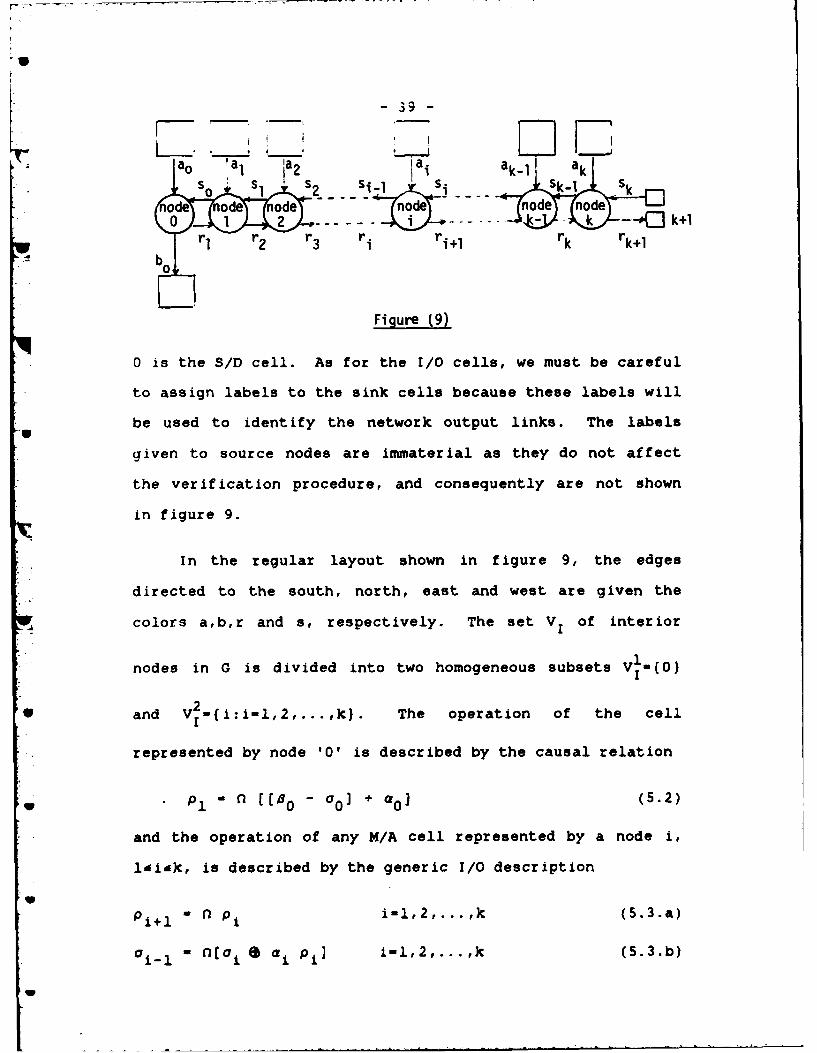
Figure 9 shows the graph of the suggested network. It
is a 2-partially homogeneous network, composed of k
multiply/add (M/A) type cells, and one subtract/divide (S/D)
cell. The computational cells are labeled by integers such
that the cells 1 through k are of the M/A type, and the cell
- 39 -
a. a, 1 aktao la, ja2 jai ak-1 ak
od de odenonode node0 1 2 k -- Jk+I
Vrl r 3 r. ri+ rk rk
. b
Figure (9)
0 is the S/D cell. As for the I/0 cells, we must be careful
to assign labels to the sink cells because these labels will
be used to identify the network output links. The labels
given to source nodes are immaterial as they do not affect
the verification procedure, and consequently are not shown
in figure 9.
In the regular layout shown in figure 9, the edges
directed to the south, north, east and west are given the
colors a,b,r and s, respectively. The set V1 of interior1
nodes in G is divided into two homogeneous subsets V,-(0)
II* and V-{i:i-l,2,... ,J}. The operation of the cell
* represented by node '0' is described by the causal relation
w Pl [0 - aO + aO ] (5.2)
and the operation of any M/A cell represented by a node i,
l'i'k, is described by the generic I/O description
Pi+l P1 il,2,...,k (5.3.a)
oi- 1 " n[o i S ai pi] i-l,2,...,k (5.3.b)
- 40 -
where thee was defined by (2.1).
To solve the system of difference equations (5.2),
(5.3.a/b), we first write the solution of (5.3.a) as
P - ni-i p1 l(i-k+l (5.4)
from which we find that
• NkPk+Jl' Pi (5.5)
Substitution of (5.4) into (5.3.b) then givesV
i-= [0o i ] (5.6)
where A. - a. * (ni- 1 P. Using an inductive argument
similar to that in the appendix for the proof of lemma 1, we
can show that the solution of (5.6) is
O 0 k O k kt n n - 1COMnO [a i P1] (5.7)
• k
For given pl, the network output sequence Pk+l is
easily obtained from (5.5). The next step will be to elim-
inate a0 from (5.2) and (5.7) and to obtain p1 explicitly
in terms of the network input sequences k, %0 and a,
J-0,l,...,k. Unfortunately, if we try to solve (5.2) and
(5.7) simultaneously, we will obtain a recursive equation in
pI' which is very difficult to manipulate in general. For
-41-
this reason, we consider only specific forms of the net-
work input sequences, namely those required for the proper
operation of the network. They are given by
a 0 e- i-01X.., (5.8.a)
0W ke 77 (5.8.b)
a k ' eL (5.8.c)
with TO.) T(t) T(71 n and
V0 1't'6i
lt't-i i~tan
V~t) - yt 1't'an
L~) - 0 1'dtan
Fri Substituting (5.8) into (5.2) and (5.7), we find that
P1 M n [fl e 00) + 03 e ko8 (5.9-a)
00onn~ e LE t in ex~ ni p1] (5.9.b)
Since O-x-O for any XeR., (5.9.a) implies the existence of
a sequence I such that
Mnk+ 1 5.0p1 -f C(.0
V whence, by (5.9.b), we find that
k C~ k k 2i+k ~C
- 42 -
lk B k IX * nli ] ]
where we used property P2 to interchange f2 j and e. If in
addition we let
kY - L ) [ "J '] (5.11)
then we can substitute for a0 and p1 in (5.9.a) and obtain
nk+l e 1 - n [[nk e nk e y] + nk e )0 ]
which reduces to
[ - + X0 (5.12)
For an explicit description of the sequence v, we need
to examine (5.11) more closely. We start by applying pro-
perty P7 to the product term in (5.11), namely
X * n I I ni Aj
where
T - min( T( )-j , T(4) ' n-j (5.13.a)
and
it(t) - x* ((t) (5.13.b)
This enables us to rewrite (5.11) as
kL) L nJ u1 (5.14)
11
U
- 43 -
From (5.14) and the definition of the '+' operator, we con-
clude that T(Y) - max(T(L) , T(MQ)+J) - n, and conse-
quently from (5.12) that
T(() - min(T(r) , T(7) , T( 0 )) - n.
Using this in (5.13.a) we easily see that T(AM) -n-J.
Now, we apply property P6 to (5.14) and explicitly describe
v by
T(7) - T(L) - n
and
0 t-i
~t-i
' (t) - (.t-3 t-2,3,...,k
j(t-J) t-k+l,k+2,... ,n
Finally, with these specific descriptions of X 0 and
.* v, we directly find the explicit form of the sequence ( in
• (5.12) to be
(t) = ( (t) -Y (t)) / )o(t)
that is
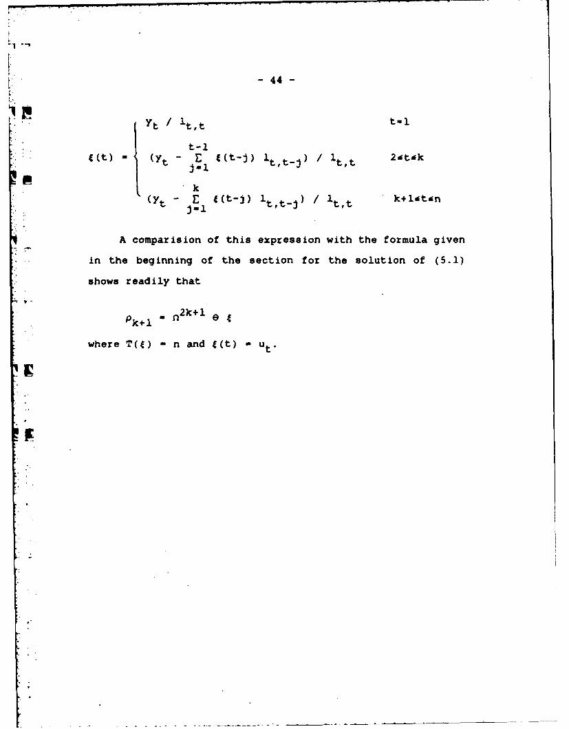
-44-
Yt / t~t t-l
A comparision of this expression with the formula given
in the beginning of the section for the solution of (5.1)
shows readily that
Pk~l 02k+1 1
where T(J) -n and 1(t) u Ut.
- 45 -
.k sorting network
The sorting network (2,9] described here accepts an
indexed set X-(xl,...,xk) of k different real numbers,
x 1 eR, icK-(l,...,k}, and produces as output the same
numbers sorted in ascending order. Figure 10 shows the gen-
eral graph of the network and the labels given to each node.
In the figure, the edges directed to the right and left are
colored s and p, respectively.
For any jeK, let yl,...,y be the result of sorting
the j elements x1 , ...,x jof X in ascending order. Then for
all (i,j) of D-{(i,j)cKxK; l'i&J'k), the ranking function
f x:D-X is defined by f x(i,))-yi.
With this, we will prove that if the network input
sequence wk is given by
Sk
nod odenod node
k+1 Sk+1 Sk Sk-1 + 1 S 2
W Figure (10)
- 46 -
9 k =e 1 (6.1)
where T(M) - k and I(t) - xt, then the network output
sequence Ok+l has the form
ak+ 1 - 2k-1 8 7 (6.2)
where T(r) - k and 7(t) - f x(t,k).
The network considered in figure 10 is a 2-partially
homogeneous network. The cell labeled '1' is a simple latchcell whose operation is described by
ao2 r n1 (6.3.a)
while the I/O description of the cells i-2,...,k is given by
i 1-1 "n maxs(Wi,oi) (6.3.b)
a i+1 n minaOi ) (6.3.c)
where maxa and min were defined in section 2.1. In other
words, the cells i-2,...,k are comparision cells which
operate as follows: At any time t, if neither one of the two
inputs oi(t) or 7I(t) is a don't care element 8, then the
cell compares the two inputs, and produces as output at time
tel, the largest and the smallest numbers on the links pl
and si+l respectively. However, if any of the inputs is 8,
9, then the cell acts as a simple latch cell, that is, if
ai(t)-8 or vi (t)-8 then
p
-47-
wi...(t+1) - l~(t) and ai+i(t+l) a ai(t)
To obtain the network 1/O description, the system of
equations (6.3.a/b/c) should be solved for akil* However,
the recursive nature of (6.3.b) and (6.3.c) makes this very
difficult, if not impossible. One possible alternative is
to suggest a tentative value for the sequences vwi anda
and then to verify that these suggested solutions indeed
satisfy (6.3). Of course, any assumed value for i should
reduce to the input sequence (6.1) for i-k.
Let us assume that v and a. are given by
a 1 0k+i-2 e 43 2&ik+l (6.4.b)
where T(a)- T(Ai k,
a. (t)I i ()'k
and
f x(t,t+i-2) akli
O (t)-
f x(t,k) k+l-i(tdk
U
- 48 -
i. It is very easy to verify that (6.4.a) reduces to (6.1)
for i-k. Hence, our next step will be to check that (6.4)
does satisfy (6.3). For i-1, (6.4.a) reduces to
P. 9 1 M o k-i e a 1
where T(a )-k, and
t x t t-1
* max 8 (xt,fx(t-l,t-1)) l<t'k
Since f (Jj) is the maximum element inx
(Xlx 2 ...I Xj, it follows that xmfx(ltl) and
maxa(xt,fx(t-lt-l))-f X(t,t). Hence, we may write
a1(t) - f (t,t) l't'k
But from (6.4.b), we obtain for i-2
02 a ik e $2
where T(02 ) k and 02 (t) fx (t,t), ldt'k, which
proves that 2 - al , and hence a - f iT2 2 1
The next step is to show that (6.4) does satisfy
(6.3.b). For this, we sustitute (6.4) into the right hand
V side of (6.3.b) and denote the resulting sequence by p.
This gives
- 49 -
P " n max (nk-i e ai n k+i-2 e le 2-ik
Using property P2 to interchange (2(i1- ) and e in the
second operand of maxa we obtain
p W nk- (i- 1 ) e ' (6.5)
where vi - maxa(ai , ni-i $i. By definition of max., it
follows that T(Yi) - T(ai) - k, and
max~ai(t)'$i (t-i+l)) i-l<tdk
Hence with the definitions of ai(t) and 2(t) we obtain
x t ldt'i-I
.. 'i(t) max~xt , fx(t-i+l,t-l) t-i
:max~maxfx t F f x(t-ilt-l)} f fx(t-i+l,t-1) }
V, i<tk
Because of max{ max(a,b) , c) - max(a,b,c), and
f (t-it-1) < f (t-i+l,t-l), we may rewrite v1 as
rXt lit'i-l
V vi(t) -
max(xt I f(t-(i-l)t-l)} i-l(tdk
from which we find that vi(t) -aii(t), and hence, by
-50-
y(6.5) and (6.4.a), that p v This proves that (6.3.b)
is satisfied for the values of a.i and vi given by (6.4).
Finally, to check that (6.4) does satisfy (6.3.c), we
* substitute (6.4) into (6.3.c) and denote the resulting
* sequence by -r.. This gives
T -n mn a(nk-i e ]c +i-2 042&ik
W rjk-i+l e min 8 (ai , ni- i)
In view of
min a(a i , n n j-
where T (op - T (20 - k and
p1 i~(t) -
we write
T W rlk+(i+lV-2 e q. (6.6)
-From (6.6) and (6.3.c), it follows that r - a only
if 'P - l To prove this, we substitute the definitions
of a 1 (t+i-1) and 0 i(t) into opi(t) and obtain
L
-51-
Smin~max{x t+i_1 f fx(t-l,t+i-2)} f fx(t,t+i-2))
f x(t,k) k-(i-l)<t~k
But from lemma 2 in the appendix, and the fact that
fx(t,t+i-l) - f (tk) for t-k-i+l, we may write oi(t) as
fi t " f (t,t+i-l) l4t~k-i
f X(t,k) k-i<t~k
It follows that Oi(t) - Oi+1 (t) and therefore that
1 - a i+ . This completes the proof that the sequences v.
and ai of (6.4) indeed satisfy the system of equations
(6.3).
Now that (6.4.b) is known to be a valid formula for the
sequence ai, we can easily obtain the network output
sequence ak+l by setting i-k+l. This gives
= 2k - 10k+l e k+l
where T .. +) - k and k+l (t) - f x(t,k), latak which is
identical with the expected output sequence (6.2).
- 52 -
7. Concluding Remarks:
This work was meant to contribute to the area of sys-
tolic architctures in three different ways, namely, by pro-
viding a mathematical model for systolic networks, an unam-
bigious description of its input and output data, and a
technique for the verification of its operation.
The central concepts in the present model are those of
data sequences and sequence operators. Although we only
defined the few operators that were used in the examples, it
s3hould be clear that other sequence operators may be intro-
duced to model other types of computational cells.
A further step in this area is to develop a more com-
plete sequence algebra to provide a basis for a solvability
theory of the resulting system of difference equations on
sequences. More specifically, it would be desirable to
determine under which conditions an explicit analytical
solution for the system of difference equations can be
obtained. For a given network, this might determine, the
properties to be satisfied by the successor function A and
the node I/O operators in order to verify analytically the
operation of the network. If a sufficiently flexible alge-
bra of this type were available, our model might prove to be
very powerful in the design of new systolic networks.
At this point, we note that even if we cannot solve the
resulting system of equations analytically, we can still use
V
- 53 -
a numerical iterative procedure to solve it. This approach
is very close to the simulation of systolic networks, but
appears to be more general and systematic.
Finally, we note that throughout this paper we assumed
the systolic network to operate synchronously. However, the
same model and techniques can be used for asynchronous net-
works. The only difference is in the interpretation .of the
ith element of a data sequence, which now has to denote the
hi data item that appeared on a communication link instead
of the data item that appeared on that link at time t-i.
4
UW
U
U
- 54 -
References
1. Mead C. A. and Conway L. A., Introduction to VLSI sys-
tems, Addison-Wesley, Reading Mass. (1980).
2. Leiserson C. E., "Systolic Priority Queues," Proc.
St. ASISTRACT (Col.. -el = reo side It -060Y1w E SMIIA NO -sow m ,)---- ,This paper presents a mathematical model for systolic architectures for usein the verification of the operation of certain systolic networks. The I/0description of the global effect of the computations performed by the networkare obtained by solving a particular system of difference equations. The verification technique is applied to four different systolic networks proposed inthe literature.
CC F 1473 uDI710NOFINovGSIsOSSOLETE UnclassifiedS. N 0102-. L.-01A01 1 8CSCURITY CLASSIFICATION oF tw, PAG-E (SeS D2.atem.