7 Segment Display Driver Skill Level: Beginner A 7 segment display has found many uses to display decimal numbers ranging from 0—9 and other charac- ters that may be created. The scope of this arcle will cover the 7 segment display used in conjuncon with a driver IC (Integrated Circuit). The reason why a driver IC is commonly used with a 7 segment display is to dis- play a relevant decimal number obtained from a binary code usually referred to as a BCD (Binary Coded Deci- mal) which will be discussed in further detail later on in the arcle, and to ease the use of a 7 segment display as it has 8 inputs (including the decimal point) and could prove frustrang to display a decimal number using 7 switches. This BCD code will be fed into the driver on the 4Bit data inputs and will be logically analyzed inside of the IC to give the corresponding 7 outputs to display a deci- mal number. Figure 1: 7 Segment Display Inside the 7 segment display are LED’s for each segment that is visible in figure1. These LED’s do not have any resistors connected to them to limit the current, thus we will need to implement our own. What size resistors should they be? It de- pends on the maximum current rang per seg- ment which one can find in a data sheet as the ex- ample in Figure2. Figure2 : Datasheet Example OVERVIEW 7 SEGMENT DISPLAY
Transcript
7 Segment Display Driver S k i l l L e v e l : B e g i n n e r
A 7 segment display has found many uses to display
decimal numbers ranging from 0—9 and other charac-
ters that may be created. The scope of this article will
cover the 7 segment display used in conjunction with a
driver IC (Integrated Circuit). The reason why a driver IC
is commonly used with a 7 segment display is to dis-
play a relevant decimal number obtained from a binary
code usually referred to as a BCD (Binary Coded Deci-
mal) which will be discussed in further detail later on in
the article, and to ease the use of a 7 segment display
as it has 8 inputs (including the decimal point) and
could prove frustrating to display a decimal number
using 7 switches.
This BCD code will be fed into the driver on the 4Bit
data inputs and will be logically analyzed inside of the
IC to give the corresponding 7 outputs to display a deci-
mal number.
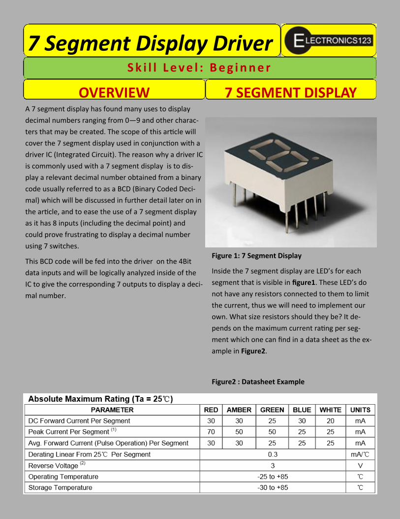
Figure 1: 7 Segment Display
Inside the 7 segment display are LED’s for each
segment that is visible in figure1. These LED’s do
not have any resistors connected to them to limit
the current, thus we will need to implement our
own. What size resistors should they be? It de-
pends on the maximum current rating per seg-
ment which one can find in a data sheet as the ex-
ample in Figure2.
Figure2 : Datasheet Example
OVERVIEW 7 SEGMENT DISPLAY
Using the information in Figure2 we can determine the
resistor size using Ohm’s Law:
Lets use a 5V supply which is preferred for digital cir-
cuits and use the appropriate current rating for the
display so focus on the “ DC Forward Current Per Seg-
ment” row and select the display colour you have.
I will use 30mA and we will give it ⅔ of the maximum
rating, thus (0.03 A / 3) X 2 which yields 20mA, the rea-
son is we do not want to run on the maximum rating as
it could lower the life span of the device and put exces-
sive current strain on the driver IC.
Our only unknown is resistance so we substitute the
values into Ohm’s law.
TIP: If 250 Ω resistors cannot be obtained try using a
higher value such as 270 Ω which we will use.
Colour Bands: RED, VIOLET, BROWN
The driver IC we will use is the 74LS47. This driver
can only be used with Common Anode displays,
Common Cathode drivers are also available but
will not work on a Common Anode display.
Figure3: 74LS47 Driver IC and Pin out
The 74LS47 Driver has an active low output repre-
sented by the little circles from a to f in the inter-
nal image of Figure3. Active low means that the
current will sink into the IC when an output is ac-
tive. This suggests that a Common Anode display is
used as the LED’s are essentially connected to the
+5V point and then connected through the resis-
tors to the outputs of the Driver IC.
PIN DEFINITIONS:
Pins( 1, 2, 6, 7 ) are the data input pins this
is where the BCD code will be applied, a
logic 1 = 2V to 5V and a logic 0 = 0v to 0.8V
Pins( 9, 10, 11, 12, 13, 14, 15) are the active
low outputs which will be connected to the
resistor's which will connect to the
7 Segment Display .
Pin( 3 ) Lamp Test, used to test all the
segments by turning them on, this pin is
R = V / I
R = Resistance ( Ω )
V = Voltage ( V )
I = Current ( A )
DRIVER IC
R = 5V / 0.02A
R = 250 Ω
V = 5 V
I = 0.02 A
also active low, so should be connected to
ground to enable it, in this experiment we will
tie it to +5V as we do not want to enable it.
Pin( 4 ) RBO used to blank screens when they
have been cascaded together.
RBO = Ripple Blanking Output Active Low.
Pin( 5 ) BI used to blank the screen.
BI = Blanking Input Active Low.
Pins( 16, 8 ) Power pins, 16 = +5V and 8 = GND.
In the BCD truth table the decimal ranges from 0 to
15 for a 4Bit Data input. The problem that arises is
that the 7 segment display can only accommodate
decimal values 0—9, so 10—15 will display other
images on the display.
Figure4: 7 Segment outputs 0—15
Note that in the truth table there’s labels (LSB) and
(MSB), LSB stands for Least Significant Bit and MSB
stands for Most Significant Bit, LSB will be taken as
your first Bit and MSB will be the last bit as follows:
(LSB) A = Bit ₀
B = Bit ₁
C = Bit ₂
(MSB) D = Bit ₃
The 4Bit input will be created using a 4 pin DIP
switch to supply +5V or 0V to represent logic 1 and
0 respectively. The switch will be implemented in
one of two configurations to prevent a floating volt-
age on the input pins which would corrupt our out-
put.
BCD TRUTH TABLE
DATA INPUTS
Decimal D (MSB) C B A (LSB)
0 0 0 0 0
1 0 0 0 1
2 0 0 1 0
3 0 0 1 1
4 0 1 0 0
5 0 1 0 1
6 0 1 1 0
7 0 1 1 1
8 1 0 0 0
9 1 0 0 1
10 1 0 1 0
11 1 0 1 1
12 1 1 0 0
13 1 1 0 1
14 1 1 1 0
15 1 1 1 1
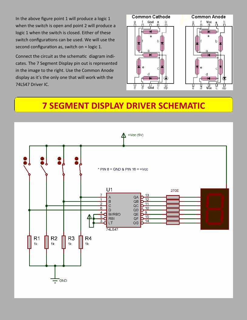
In the above figure point 1 will produce a logic 1
when the switch is open and point 2 will produce a
logic 1 when the switch is closed. Either of these
switch configurations can be used. We will use the
second configuration as, switch on = logic 1.
Connect the circuit as the schematic diagram indi-
cates. The 7 Segment Display pin out is represented
in the image to the right. Use the Common Anode
display as it’s the only one that will work with the
74LS47 Driver IC.
7 SEGMENT DISPLAY DRIVER SCHEMATIC
Once the circuit has been constructed and any prob-
lems arise they could often be solved by a few sim-