21
7 Segment Display Internet Clock Created by Philip Moyer Last updated on 2016-06-27 06:41:19 PM EDT

7 Segment Display Internet ClockCreated by Philip Moyer
Last updated on 2016-06-27 06:41:19 PM EDT

2356
111120
Guide Contents
Guide ContentsObjectiveWhat You'll NeedSoldering (aka Build It!)CodeFeatherClock CodeRun it!
© Adafruit Industries https://learn.adafruit.com/7-segment-display-internet-clock Page 2 of 21

Objective
When I saw these 7 segment displays with FeatherWing backpacks on Ask an Engineer, I got reallyexcited. I love clocks! I have the original Ice Tube clock from Adafruit, plus the PiGlow daughter cardbinary clock, plus my collection of watches (including a programmable TI digital watch that I've re-programmed to display Martian Standard Time and the current Sol). So the thought of having a mobileclock with a colored display made me immediately run to the shop and buy three colors (and a CircuitPlayground, but that's for another tutorial).
This clock design uses NTP (Network Time Protocol) to always display the accurate time,synchronized to the same clocks that run the Internet!
© Adafruit Industries https://learn.adafruit.com/7-segment-display-internet-clock Page 3 of 21

Follow along to build your own ultra-precision clock that always has the exact right time, synced toInternet atomic-accuracy clocks!
© Adafruit Industries https://learn.adafruit.com/7-segment-display-internet-clock Page 4 of 21

What You'll NeedI'm not going to include my usual architecture diagram because this device is pure simplicity. It's just aFeather Doubler with a 7 segment LED FeatherWing (http://adafru.it/nej) (in the color of your choice),along with a Feather M0 WiFi (http://adafru.it/3010)with an OLED FeatherWing ontop (http://adafru.it/2900) (for debugging output). You can get all the parts you need from the shop -see the list at the right. You'll also need a soldering station for the light soldering needed to put theheaders on the boards and the LED block onto the Backpack.
Here are the components after soldering but before assembly:
© Adafruit Industries https://learn.adafruit.com/7-segment-display-internet-clock Page 5 of 21
Soldering (aka Build It!)As with all Feathers and Wings, you have a choice of headers to solder on. I recommend the FeatherStacking headers for the Feather M0 WiFi itself, the included male header strips for the 7 segmentbackpack FeatherWing and OLED FeatherWing, and the Feather Header Kit for the Doubler (theDoubler comes with one pair of stacking headers and one pair of normal headers; I prefer the normalheaders, so I always order an extra Feather Header Kit with each Doubler I get).
This header arrangement maximizes the visibility of the LED display (and I don't think other headerswill fit along with the LED display anyway).
If you are new to soldering, read one of the excellent guides to perfect soldering (http://adafru.it/dxy).
First, solder the stacking headers onto the Feather M0 WiFi. Put the male pins below the board andthe female header above the board. Tack down one pin first, then eyeball it to make sure the headersare at 90 degree angles to the board. When you're satisfied with the alignment, solder the rest of thepins. Repeat with the other piece of stacking header.
Second, solder the headers you like onto the Doubler. Be careful to be sure they are at a 90 degreeangle to the Doubler. If you want, you can put the Feather into the headers when you solder them in toassist with the alignment. This might make soldering them in straight a little easier.
After you have the Doubler constructed, put the Feather M0 WiFi in it. Make sure the JST connectorfor the battery is on the outside edge.
© Adafruit Industries https://learn.adafruit.com/7-segment-display-internet-clock Page 6 of 21
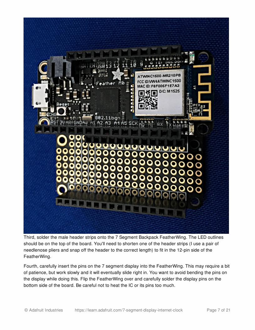
Third, solder the male header strips onto the 7 Segment Backpack FeatherWing. The LED outlinesshould be on the top of the board. You'll need to shorten one of the header strips (I use a pair ofneedlenose pliers and snap off the header to the correct length) to fit in the 12-pin side of theFeatherWing.
Fourth, carefully insert the pins on the 7 segment display into the FeatherWing. This may require a bitof patience, but work slowly and it will eventually slide right in. You want to avoid bending the pins onthe display while doing this. Flip the FeatherWing over and carefully solder the display pins on thebottom side of the board. Be careful not to heat the IC or its pins too much.
© Adafruit Industries https://learn.adafruit.com/7-segment-display-internet-clock Page 7 of 21

Put the 7 segment FeatherWing on the other side of the Doubler.
© Adafruit Industries https://learn.adafruit.com/7-segment-display-internet-clock Page 8 of 21
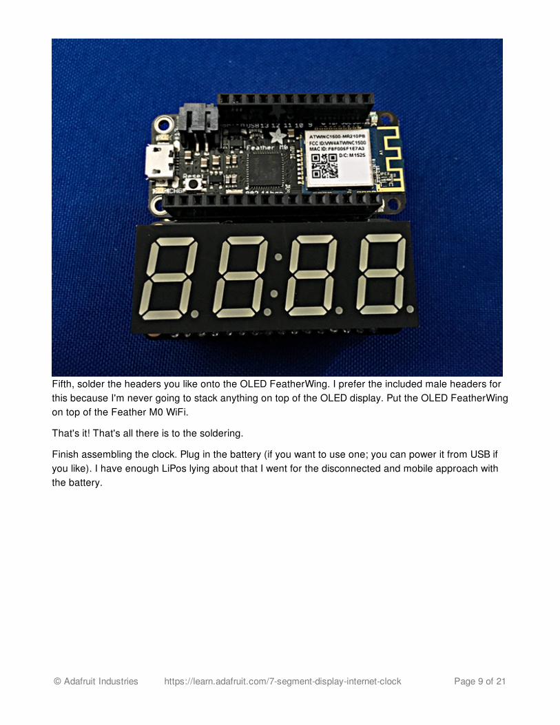
Fifth, solder the headers you like onto the OLED FeatherWing. I prefer the included male headers forthis because I'm never going to stack anything on top of the OLED display. Put the OLED FeatherWingon top of the Feather M0 WiFi.
That's it! That's all there is to the soldering.
Finish assembling the clock. Plug in the battery (if you want to use one; you can power it from USB ifyou like). I have enough LiPos lying about that I went for the disconnected and mobile approach withthe battery.
© Adafruit Industries https://learn.adafruit.com/7-segment-display-internet-clock Page 9 of 21

Next: the Code
© Adafruit Industries https://learn.adafruit.com/7-segment-display-internet-clock Page 10 of 21

CodeBefore you start, go through the following guides:
Feather M0 Wifi Guide (http://adafru.it/ne7)OLED Featherwing Guide (http://adafru.it/nek)7-segment Featherwing Guide (http://adafru.it/nel)
To make sure you have installed all the drivers, Arduino libraries, and examples. Make sure you havecode uploading and the examples running before you continue to this combined code example!
FeatherClock CodeI based my code on examples from the libraries - namely the WiFiUdpNtpClient example from theWINC1500 library and the clock_sevenseg_ds1307 example from the LED Backpack Library. Imodified both to meet the needs of this project.
You will need to modify three things in the below code to make the clock work.
First, change YOUR_SSID to the SSID for your wireless network.Second, change YOUR_WIFI_PASSWORD to the actual password for your SSID network.Third, change the tzOffset variable to be the correct offset from UTC for your timezone. Thecode below is configured for the East Coast of the US (Eastern Standard Time - tzOffset = -4). Ifyou'd like your clock to display UTC, simply set the tzOffset to zero.
//###############################################################################// FeatherClock - Use the Adafruit seven segment LED FeatherWing to display the// current time, which we fetch from the Internet using NTP. This program assumes// the seven segment display is attached to a Feather M0 WiFi (WINC1500).//// At the top of every hour, re-sync with NTP to correct for any drift.//// Credit: This is based heavily on the work by Tony DiCola from Adafruit.// Suggest (strongly) you go to adafruit.com and buy some product from// them. WINC1500 code modified from example code provided by Michael Margolis and// Tom Igoe.//// Philip R. Moyer// Adafruit//// This source code is in the public domain and is released under the BSD license.// Any further redistribution must include this header.////###############################################################################
© Adafruit Industries https://learn.adafruit.com/7-segment-display-internet-clock Page 11 of 21

//###############################################################################// Includes and defines//###############################################################################
#ifdef __AVR__ #include <avr/power.h>#endif
#include <SPI.h> // SPI interface API#include <Adafruit_WINC1500.h> // WINC1500 wireless header#include <Adafruit_WINC1500Udp.h> // WINC1500 UDP support#include <Wire.h> // Wire support library#include "Adafruit_LEDBackpack.h" // Support for the LED Backpack FeatherWing#include "Adafruit_GFX.h" // Adafruit's graphics library#include <Adafruit_SSD1306.h> // OLED support library
#define WINC_CS 8 // WINC1500 Chip Select#define WINC_IRQ 7 // WINC1500 interrupt request line#define WINC_RST 4 // WINC1500 reset line#define WINC_EN 2 // WINC1500 enable
#define OLED_RESET 3 // OLED reset pin
#define LOGO16_GLCD_HEIGHT 16 // Adafruit logo height#define LOGO16_GLCD_WIDTH 16 // Adafruit logo widthstatic const unsigned char PROGMEM logo16_glcd_bmp[] ={ B00000000, B11000000, B00000001, B11000000, B00000001, B11000000, B00000011, B11100000, B11110011, B11100000, B11111110, B11111000, B01111110, B11111111, B00110011, B10011111, B00011111, B11111100, B00001101, B01110000, B00011011, B10100000, B00111111, B11100000, B00111111, B11110000, B01111100, B11110000, B01110000, B01110000, B00000000, B00110000 };
#if (SSD1306_LCDHEIGHT != 32)#error("Height incorrect, please fix Adafruit_SSD1306.h!");#endif
#define VBATPIN 9 // Pin to read battery voltage
© Adafruit Industries https://learn.adafruit.com/7-segment-display-internet-clock Page 12 of 21

//###############################################################################// Globals//###############################################################################
#define TIME_24_HOUR true#define DISPLAY_ADDRESS 0x70
// Create display objectAdafruit_7segment clockDisplay = Adafruit_7segment();
int hours = 0; // Track hoursint minutes = 0; // Track minutesint seconds = 0; // Track secondsint tzOffset = -4; // Time zone offset
bool blinkColon = false; // Track the status of the colon to blink every second
// Set up the WINC1500 chip with the above pins and default hardware SPI.Adafruit_WINC1500 WiFi(WINC_CS, WINC_IRQ, WINC_RST);
int status = WL_IDLE_STATUS; // WINC1500 chip statuschar ssid[] = "YOUR_SSID"; // WiFi network SSIDchar pass[] = "YOUR_WIFI_PASSWORD"; // WiFi password (NOTE: redact before doing a git push!!!)
unsigned int localPort = 2390; // Local port to listen for UDP packetsIPAddress timeServer(129,6,15,28); // time.nist.gov NTP serverconst int NTP_PACKET_SIZE = 48; // NTP time stamp is in the first 48 bytesbyte packetBuffer[NTP_PACKET_SIZE]; // Buffer for incoming and outgoing UDP packets
Adafruit_WINC1500UDP Udp; // Set up a WINC1500 client session
Adafruit_SSD1306 display(OLED_RESET); // Instantiate the OLED control object
//###############################################################################// Functions//###############################################################################
// send an NTP request to the time server at the given addressunsigned long sendNTPpacket(IPAddress& address){ //Serial.println("1"); // set all bytes in the buffer to 0 memset(packetBuffer, 0, NTP_PACKET_SIZE); // Initialize values needed to form NTP request // (see URL above for details on the packets)
© Adafruit Industries https://learn.adafruit.com/7-segment-display-internet-clock Page 13 of 21

//Serial.println("2"); packetBuffer[0] = 0b11100011; // LI, Version, Mode packetBuffer[1] = 0; // Stratum, or type of clock packetBuffer[2] = 6; // Polling Interval packetBuffer[3] = 0xEC; // Peer Clock Precision // 8 bytes of zero for Root Delay & Root Dispersion packetBuffer[12] = 49; packetBuffer[13] = 0x4E; packetBuffer[14] = 49; packetBuffer[15] = 52;
//Serial.println("3");
// all NTP fields have been given values, now // you can send a packet requesting a timestamp: Udp.beginPacket(address, 123); //NTP requests are to port 123 //Serial.println("4"); Udp.write(packetBuffer, NTP_PACKET_SIZE); //Serial.println("5"); Udp.endPacket(); //Serial.println("6");}
void printWiFiStatus() { // print the SSID of the network you're attached to: Serial.print("SSID: "); Serial.println(WiFi.SSID());
// print your WiFi shield's IP address: IPAddress ip = WiFi.localIP(); Serial.print("IP Address: "); Serial.println(ip);
// print the received signal strength: long rssi = WiFi.RSSI(); Serial.print("signal strength (RSSI):"); Serial.print(rssi); Serial.println(" dBm");}
void printData() { float measuredvbat = analogRead(VBATPIN);
measuredvbat *= 2; // we divided by 2, so multiply back measuredvbat *= 3.3; // Multiply by 3.3V, our reference voltage measuredvbat /= 1024; // convert to voltage
© Adafruit Industries https://learn.adafruit.com/7-segment-display-internet-clock Page 14 of 21
display.clearDisplay(); display.setCursor(0,0); display.print("VBat: "); display.print(measuredvbat); display.println(" volts"); display.display();}
//###############################################################################// Setup - main//###############################################################################
// This is one of the two standard functions for every Arduino program, with the// other being loop(). This one runs once at the beginning of the program execution// and is ordinarily used to initialize hardware and variables.
void setup() {#ifdef WINC_EN pinMode(WINC_EN, OUTPUT); digitalWrite(WINC_EN, HIGH);#endif
Serial.begin(115200); // Start the serial console Serial.println("Clock starting!"); // Start the clock message.
// Make sure we have WiFi hardware, or there's no point continuing. if (WiFi.status() == WL_NO_SHIELD) { while (true); // Spin loop }
// Take a moment to initialize the OLED display and put up the Adafruit splash screen // by default, we'll generate the high voltage from the 3.3v line internally! (neat!) display.begin(SSD1306_SWITCHCAPVCC, 0x3C); // initialize with the I2C addr 0x3C (for the 128x32)
// Show image buffer on the display hardware. // Since the buffer is intialized with an Adafruit splashscreen // internally, this will display the splashscreen. display.display(); delay(2000);
// Clear the buffer. display.clearDisplay();
display.setTextSize(1); display.setTextColor(WHITE);
// Now back to the setup
© Adafruit Industries https://learn.adafruit.com/7-segment-display-internet-clock Page 15 of 21

// Set up the display. clockDisplay.begin(DISPLAY_ADDRESS);
// Attempt to conect to the WiFi network. Serial.println("Connecting to WiFi netowrk."); while (WiFi.status() != WL_CONNECTED) { status = WiFi.begin(ssid, pass); // Connect to WPA2 network uint8_t timeout = 10; // Set a timeout variable while (timeout && (WiFi.status() != WL_CONNECTED)) { timeout--; // Decrement timeout delay(1000); // Delay for one second } }
Serial.println("Connected to network."); printWiFiStatus(); // Display WiFi status data
Udp.begin(localPort); // Open the UDP port for comms}
//###############################################################################// Loop - main//###############################################################################
// This is one of the two standard functions for every Arduino program, with the// other being setup(). This one runs continuously, forever, and executes the// Arduino program code.
void loop() { // Refresh the time at the top of every hour, or every five minutes because // the clock drift on the bare Feather M0 is pretty wicked. if ((minutes == 0) || ((minutes % 5) == 0)) { sendNTPpacket(timeServer); // send an NTP packet to a time server // wait to see if a reply is available delay(1000); if ( Udp.parsePacket() ) { Serial.println("packet received"); // We've received a packet, read the data from it Udp.read(packetBuffer, NTP_PACKET_SIZE); // read the packet into the buffer
//the timestamp starts at byte 40 of the received packet and is four bytes, // or two words, long. First, esxtract the two words:
unsigned long highWord = word(packetBuffer[40], packetBuffer[41]); unsigned long lowWord = word(packetBuffer[42], packetBuffer[43]); // combine the four bytes (two words) into a long integer // this is NTP time (seconds since Jan 1 1900): unsigned long secsSince1900 = highWord << 16 | lowWord; Serial.print("Seconds since Jan 1 1900 = " );
© Adafruit Industries https://learn.adafruit.com/7-segment-display-internet-clock Page 16 of 21
Serial.println(secsSince1900);
// now convert NTP time into everyday time: Serial.print("Unix time = "); // Unix time starts on Jan 1 1970. In seconds, that's 2208988800: const unsigned long seventyYears = 2208988800UL; // subtract seventy years: unsigned long epoch = secsSince1900 - seventyYears; // print Unix time: Serial.println(epoch);
// print the hour, minute and second: Serial.print("The UTC time is "); // UTC is the time at Greenwich Meridian (GMT) hours = ((epoch % 86400L) / 3600); // print the hour (86400 equals secs per day) hours += tzOffset; // Calculate the time zone offset if (hours < 0) { hours = 24 + hours; } if (hours > 23) { hours = hours - 23; } Serial.print(hours); // print the hour Serial.print(':'); minutes = ((epoch % 3600) / 60); if (minutes < 10 ) { // In the first 10 minutes of each hour, we'll want a leading '0' Serial.print('0'); } Serial.print(minutes); // print the minute (3600 equals secs per minute) Serial.print(':'); seconds = (epoch % 60); // print the second if ( seconds < 10 ) { // In the first 10 seconds of each minute, we'll want a leading '0' Serial.print('0'); } Serial.println(seconds); } } // Display the time int displayValue = hours*100 + minutes;
if (!TIME_24_HOUR) { if (hours > 12) { displayValue -= 1200; } else if (hours == 0) { displayValue += 1200; } }
© Adafruit Industries https://learn.adafruit.com/7-segment-display-internet-clock Page 17 of 21

// Print the time on the display clockDisplay.print(displayValue, DEC);
// Add zero padding when in 24 hour mode and it's midnight. // In this case the print function above won't have leading 0's // which can look confusing. Go in and explicitly add these zeros. if (TIME_24_HOUR && hours == 0) { // Pad hour 0. clockDisplay.writeDigitNum(1, 0); // Also pad when the 10's minute is 0 and should be padded. if (minutes < 10) { clockDisplay.writeDigitNum(2, 0); } }
// Blink the colon by flipping its value every loop iteration // (which happens every second). blinkColon = !blinkColon; clockDisplay.drawColon(blinkColon);
// Now push out to the display the new values that were set above. clockDisplay.writeDisplay();
// Pause for a second for time to elapse. This value is in milliseconds // so 1000 milliseconds = 1 second. delay(1000);
// Now increase the seconds by one. seconds += 1; // If the seconds go above 59 then the minutes should increase and // the seconds should wrap back to 0. if (seconds > 59) { seconds = 0; minutes += 1; // Again if the minutes go above 59 then the hour should increase and // the minutes should wrap back to 0. if (minutes > 59) { minutes = 0; Serial.println("Minutes set to zero - should query NTP on next loop()"); hours += 1; // Note that when the minutes are 0 (i.e. it's the top of a new hour) // then the start of the loop will read the actual time from NTP // again. Just to be safe though we'll also increment the hour and wrap // back to 0 if it goes above 23 (i.e. past midnight). if (hours > 23) { hours = 0; } }
© Adafruit Industries https://learn.adafruit.com/7-segment-display-internet-clock Page 18 of 21

} printData(); // Display battery voltage on the OLED}
OK upload it to your Feather M0 WiFi!
© Adafruit Industries https://learn.adafruit.com/7-segment-display-internet-clock Page 19 of 21

Run it!Connect your Feather M0 WiFi to your laptop or other Arduino programming environment and load thecode into the board. Be sure to modify YOUR_SSID and YOUR_WIFI_PASSWORD to match your ownnetwork!
If you have not yet modified your board manager to include the Adafruit Feather, go check out theinstructions in LadyAda's Feather M0 WiFi learning system tutorial (http://adafru.it/ne7). Once youhave done this, your board should show up as "Adafruit Feather M0 (Native USB Port)". It should alsoshow up on the correct port, but check these values just to be sure.
You will need to have the WINC1500 library, the LEDbackpack library, and the GFX library installed.The pin specification in the code on the previous page is correct for this hardware configuration.
Follow these guides
Feather M0 Wifi Guide (http://adafru.it/ne7)OLED Featherwing Guide (http://adafru.it/nek)7-segment Featherwing Guide (http://adafru.it/nel)
To make sure you have installed all Arduino libraries! Make sure you have code uploading and theexamples running before you compile and upload this code since you will not be able to compile thecode otherwise!
(If you need some help with installation of Arduino libraries, there is an excellent tutorial at http://learn.adafruit.com/adafruit-all-about-arduino-libraries-install-use (http://adafru.it/aYM) )
Download the Adafruit_WINC1500 Library
http://adafru.it/kVa
Download the Adafruit LED Backpack Library
http://adafru.it/ncm
© Adafruit Industries https://learn.adafruit.com/7-segment-display-internet-clock Page 20 of 21

Download the Adafruit GFX Library
http://adafru.it/cBBTest your environment by compiling the code. Once it's compiling cleanly, upload the code to yourFeather.
That's it! You now have an LED clock that's portable! The OLED display will show the current batteryvoltage which will tell you when it's time for a recharge. Enjoy your clock!
© Adafruit Industries Last Updated: 2016-06-27 06:41:18 PM EDT Page 21 of 21


