Introduction The 70 Series GO Switch with connection head assembly provides the reliability of the GO Switch for use in increased safety applications. The connection head is available with an M20 or 1/2 NPT conduit entry and has labeled terminal blocks for ease of end user installation. GO Switches operate on the principle of magnetic attrac-tion, reacting to ferrous metal or magnetic targets as they come within the switch's sensing range. Although switches vary in design according to their intended applications, all GO Switches use permanent magnets which, when actuated by the presence of a fer-rous or magnetic target, change the state of electrical contacts. Mounting
• 70 Series GO Switches are unaffected by weld fields and RF interference.
• 70 Series GO Switches may be mount-ed adjacent to or surrounded by ferrous metals however the proximity of ferrous metals will affect sensing distance. For the maximum rated sensing distance, avoid mounting near ferrous metals. The switch / terminal assembly is bonded together by the internal cement/potting. Any attempt to separate the parts (except the threaded cover) will void the warranty and certifica-tion
• GO Switches sense ferrous materials such as mild steel, 400 series and 17/4 stainless steel.
• Sensing and differential of switch may vary depending on target travel direction.
• Avoid contact between target and switch. Configure mounting of switch and/or target so that target passes within the sensing area. Sensing range will vary according to model number and mass of target used.
• Target magnets, available through TopWorx, will increase the sensing range of the switch. Reference sensing ranges in corresponding sections throughout the catalog.
• For optimum performance, provide sufficient mass of target, and choose the appropriate GO Switch model to match the application requirements for operating frequency, type of load, etc.
• Greater target mass and target move-ment fully into and out of sensing range will increase contact pressure. This is helpful in low current controls applications.
• For heavy or inductive loads, arc sup-pression devices or interposing relays are recommended for contact longevity. Con-tact factory for specifics.
• Do not use excessive force on external threads when installing. (36 in/lbs. max)
• Configure mounting so bracket dissects switch as close to the middle of the body as possible. This eliminates undue stress caused by heavy cables, connectors, etc.
• Configure mounting so bracket dissects switch as close to the middle of the body as possible. This eliminates undue stress caused by heavy cables, connectors, etc.
• Two appropriately sized jam nuts are included with switch. Lock washers are recommended where vibration is present. Specifications - SPDT Sensing Distance: 73, 75, 77: .100” (2.54mm) 2,000 PSI 73, 75, 77: .072” (1.83mm) 5,000 PSI 73, 75, 77: .060” (1.52mm)10,000 PSI Range with Target Magnet: Up to .35” (9mm) Differential:
Approx. .020" (.5mm) Repeatability: .002" (0.05mm) Under identical operating conditions Response time: 8 milliseconds Thread Options: 73, 75: 5/8-18 UNF; M18 x 1 77: 3/4-16 UNF; M20 x 1.5 Temperature Rating:
T4 Tamb = -40°C to +100°C T6 Tamb = -40°C to +50°C Contact Material:
Palladium silver with Sawtooth® surface Configuration Contacts:
8 milliseconds Thread Options: 7G: 5/8"-18 UNF; M18 x 1 7I: 1"-14 UNF Temperature Rating: T4 Tamb = -40°C to +100°C T6 Tamb = -40°C to +50°C Contact Material: Palladium silver with Sawtooth® surface Configuration Contacts: Double Pole Double Throw, 2 Form C. Electrical Ratings: Resistive 3A @ 120VAC / 1A @ 24VDC Target Material:
Ferrous metal; optional target magnets Connection Head Conduit Outlet: 1/2" -14NPT or M20. One location. Enclosure Material:
70 Series GO Switch: 303 or 316 SST Connection Head: Die Cast Aluminum with Silicone o-ring
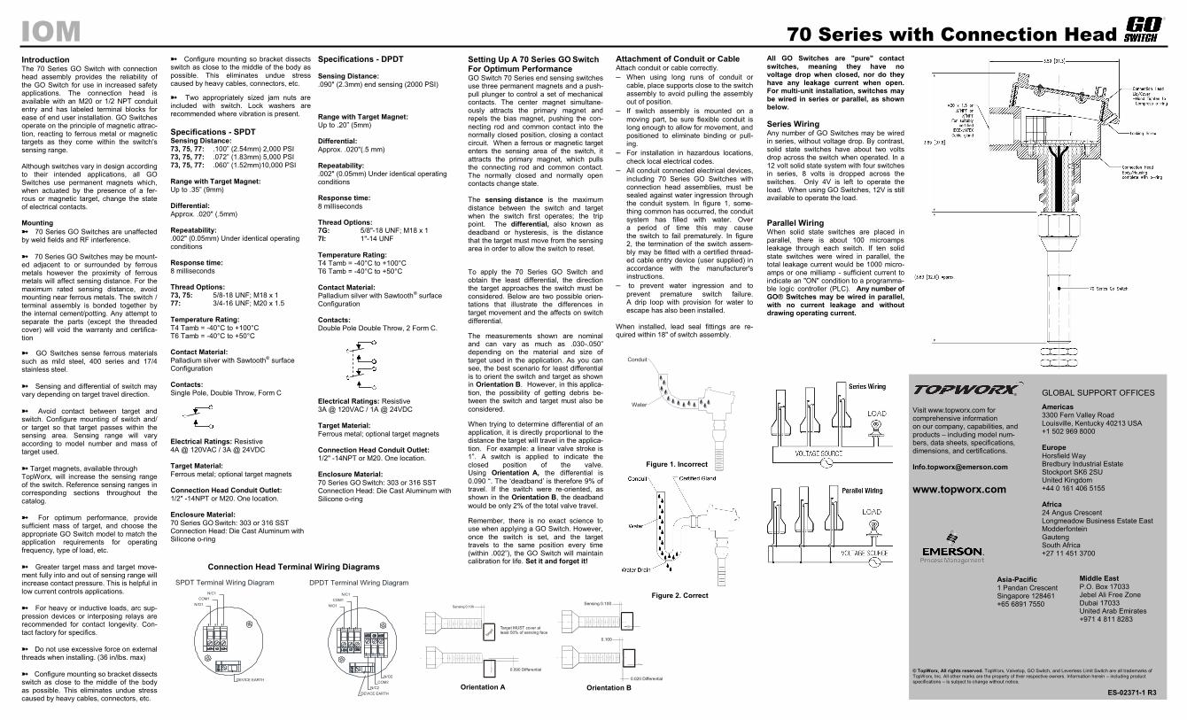
Setting Up A 70 Series GO Switch For Optimum Performance GO Switch 70 Series end sensing switches use three permanent magnets and a push-pull plunger to control a set of mechanical contacts. The center magnet simultane-ously attracts the primary magnet and repels the bias magnet, pushing the con-necting rod and common contact into the normally closed position, closing a contact circuit. When a ferrous or magnetic target enters the sensing area of the switch, it attracts the primary magnet, which pulls the connecting rod and common contact. The normally closed and normally open contacts change state. The sensing distance is the maximum
distance between the switch and target when the switch first operates; the trip point. The differential, also known as deadband or hysteresis, is the distance that the target must move from the sensing area in order to allow the switch to reset.
To apply the 70 Series GO Switch and obtain the least differential, the direction the target approaches the switch must be considered. Below are two possible orien-tations that illustrate the differences in target movement and the affects on switch
differential.
The measurements shown are nominal and can vary as much as .030-.050” depending on the material and size of target used in the application. As you can see, the best scenario for least differential is to orient the switch and target as shown in Orientation B. However, in this applica-
tion, the possibility of getting debris be-tween the switch and target must also be
considered.
When trying to determine differential of an application, it is directly proportional to the distance the target will travel in the applica-tion. For example: a linear valve stroke is 1”. A switch is applied to indicate the closed position of the valve. Using Orientation A, the differential is
0.090 “. The ‘deadband’ is therefore 9% of travel. If the switch were re-oriented, as shown in the Orientation B, the deadband
would be only 2% of the total valve travel.
Remember, there is no exact science to use when applying a GO Switch. However, once the switch is set, and the target travels to the same position every time (within .002”), the GO Switch will maintain calibration for life. Set it and forget it!
Sensing 0.100
0.090 Differential
Targ
et
Target MUST cover atleast 50% of sensing face
Orientation A
0.100
Sensing 0.100
0.020 Differential
Orientation B
Attachment of Conduit or Cable Attach conduit or cable correctly.
– When using long runs of conduit or
cable, place supports close to the switch assembly to avoid pulling the assembly out of position.
– If switch assembly is mounted on a
moving part, be sure flexible conduit is long enough to allow for movement, and positioned to eliminate binding or pull-ing.
– For installation in hazardous locations,
check local electrical codes. – All conduit connected electrical devices,
including 70 Series GO Switches with connection head assemblies, must be sealed against water ingression through the conduit system. In figure 1, some-thing common has occurred, the conduit system has filled with water. Over a period of time this may cause the switch to fail prematurely. In figure 2, the termination of the switch assem-bly may be fitted with a certified thread-ed cable entry device (user supplied) in accordance with the manufacturer's instructions.
– to prevent water ingression and to
prevent premature switch failure. A drip loop with provision for water to escape has also been installed.
When installed, lead seal fittings are re-quired within 18" of switch assembly.
All GO Switches are "pure" contact switches, meaning they have no voltage drop when closed, nor do they have any leakage current when open. For multi-unit installation, switches may be wired in series or parallel, as shown below.
Series Wiring Any number of GO Switches may be wired in series, without voltage drop. By contrast, solid state switches have about two volts drop across the switch when operated. In a 12 volt solid state system with four switches in series, 8 volts is dropped across the switches. Only 4V is left to operate the load. When using GO Switches, 12V is still available to operate the load.
Parallel Wiring When solid state switches are placed in parallel, there is about 100 microamps leakage through each switch. If ten solid state switches were wired in parallel, the total leakage current would be 1000 micro-amps or one milliamp - sufficient current to indicate an "ON" condition to a programma-ble logic controller (PLC). Any number of GO® Switches may be wired in parallel, with no current leakage and without drawing operating current.
Visit www.topworx.com for comprehensive information on our company, capabilities, and products – including model num-bers, data sheets, specifications, dimensions, and certifications. [email protected]
TopWorx, Inc. All other marks are the property of their respective owners. Information herein – including product specifications – is subject to change without notice.
GLOBAL SUPPORT OFFICES
Americas 3300 Fern Valley Road Louisville, Kentucky 40213 USA +1 502 969 8000 Europe
Horsfield Way Bredbury Industrial Estate Stockport SK6 2SU United Kingdom +44 0 161 406 5155 Africa 24 Angus Crescent Longmeadow Business Estate East Modderfontein Gauteng South Africa +27 11 451 3700
P.O. Box 17033 Jebel Ali Free Zone Dubai 17033 United Arab Emirates +971 4 811 8283
Technical Assistance • TopWorx engineers are available to provide technical assistance on GO™ Switch products. However, it is the cus-tomer's responsibility to determine the safety and suitability of the product in their application. It is also the customer's re-sponsibility to install the switch using the current electrical codes in their region.
Special Conditions for Safe Use • The 70 Series GO Switch with Connection Head assembly shall be suitably earthed by its installation via the male thread of the GO Switch body.
• Do not allow dust layers to build up on this product.
• All terminal screws, used and unused, shall be fully tight-ened down by end user.
• No more than one single multi-stranded lead shall be connected to the terminal unless multiple conductors have been joined in a suitable manner, e.g. two conductors into a single insulated bootlace ferrule, or any method indicated on the terminal certificate.
• All terminals and accessories, such as cross-connectors, shall be installed in accordance with the terminal manufactur-er’s instructions. TopWorx Incorporated will supply the rele-vant terminal manufacturer’s instructions with each assembly covered by Baseefa09ATEX0281X & IECEx BAS 09.0135X certificates.
• The maximum voltage and current shown in the rating label must not be exceeded.
• When connecting conductors of cross section below the maximum 2.3mm³ allowed for the terminal, then the maximum amps per pole must be reduced inline with the maximum amps permitted for a terminal equivalent to the conductor size fitted.
IOM
Air and Hydraulic Cylinders A ferrous cylinder cushion or piston will actuate the switch. To determine the correct thread length, measure the distance from the head cap surface to the cushion and add 1/2" for seal nut. Thread seal nut onto switch. Screw switch into cylinder by hand until switch touches cushion. Back out 1/4 to 1/2 turn. Tighten seal nut.
5/8" Diameter/18mm Torque Jam Nuts to: 15 lbs-ft to achieve seal at 2,000 PSI 25 lbs-ft to achieve seal at 5,000 PSI Do not exceed 30 lbs-ft Models 77: 3/4" Diameter/20mm Torque Jam Nuts to:
20 lbs-ft to achieve seal at 2,000 PSI 65 lbs-ft to achieve seal at 5,000 PSI Do not exceed 75 lbs-ft Models 7I:
1" Diameter Torque Jam Nuts to: 25 lbs-ft to achieve seal at 2,000 PSI 75 lbs-ft to achieve seal at 5,000 PSI Do not exceed 125 lbs-ft
Baseefa09ATEX0281X IECEx BAS 09.0135X Ex de IIC T4/T6 Gb Ex tb IIIC T130°C/T85°C Db IP66 T4/T130°C Tamb: -40°C to + 100°C T6/T85°C Tamb: -40°C to + 50°C
0518 II 2 GD
6. LIMITATION OF REMEDY AND LIABILITY: SELLER SHALL NOT BE LIABLE FOR DAMAGES CAUSED BY DELAY IN PERFORMANCE. THE REMEDIES OF BUYER SET FORTH IN THIS AGREEMENT ARE EXCLU-SIVE. IN NO EVENT, REGARDLESS OF THE FORM OF THE CLAIM OR CAUSE OF ACTION (WHETHER BASED IN CONTRACT, INFRINGEMENT, NEGLIGENCE, STRICT LIABILITY, OTHER TORT OR OTHERWISE), SHALL SELLER’S LIABILITY TO BUYER AND/OR ITS CUSTOMERS EXCEED THE PRICE TO BUYER OF THE SPECIFIC GOODS MANUFACTURED OR SERVICES PROVIDED BY SELLER GIVING RISE TO THE CLAIM OR CAUSE OF ACTION. BUYER AGREES THAT IN NO EVENT SHALL SELLER’S LIABILITY TO BUYER AND/OR ITS CUSTOMERS EXTEND TO INCLUDE INCIDENTAL, CONSEQUENTIAL OR PUNITIVE DAMAGES. THE TERM “CONSEQUENTIAL DAMAGES” SHALL INCLUDE, BUT NOT BE LIMITED TO, LOSS OF ANTICIPATED PROFITS, REVENUE OR USE AND COSTS INCURRED INCLUDING WITHOUT LIMITATION FOR CAPITAL, FUEL AND POWER, AND CLAIMS OF BUYER’S CUSTOMERS. 7. PATENTS: Subject to the limitations contained in Section 6, Seller shall defend any suits brought against Buyer based on a claim that use of the Goods manufactured by Seller constitutes an infringement of a valid patent of the United States, and shall pay any damages awarded therein against Buyer, provided that Buyer: promptly notifies Seller in writing of the filing of such suit or the threat thereof; permits Seller to control completely the defense or compro-mise of such claim of infringement; and provides all reasonable assistance and cooperation requested by Seller for the defense of such suit. In the event that only the Goods manufactured by Seller are held to be infringing in such suit and their use is enjoined, Seller shall, at its sole option and expense, provide a commercially reasonable alternative, including, but not limited to, procuring for Buyer the right to continue using the Goods, replacing them with a non-infringing product or modifying them so they become non-infringing. Buyer agrees that Seller shall not be liable for infringement, and that Buyer shall fully indemnify Seller therefore, if infringement is based upon the use of Goods in connection with goods not manufactured by Seller or in a manner for which the Goods were not designed by the Seller or if the Goods were not designed by the Seller or if the Goods were designed by the Buyer or were modified by or for the Buyer in a manner to cause them to become infringing. 8. TAXES: Any tax or governmental charge payable by the Seller because of the manufacture, sale or delivery of the Goods, or provision of Services, may at Seller's option be added to the price herein specified. The foregoing shall not apply to taxes based upon Seller’s net income. 9. TERMS OF PAYMENT: Subject to the approval of Seller's Credit Depart-ment, terms are F.O.B. shipping point, net 30 days from date of Seller's invoice in U.S. currency, except for applicable milestone payments covered below or export shipments for which Seller may require other arrangements. Freight charges may include shipping and handling charges, and Buyer shall pay all such charges. If any payment owed to Seller hereunder is not paid when due, it shall bear interest at a rate 1-1/2% per month interest from the date on which it is due until it is received and future shipments may be placed on hold. Seller shall have the right, among other remedies, either to terminate the Agreement or to suspend further deliveries under this and/or other agreements with Buyer in the event Buyer fails to make any payment hereunder when due. Buyer shall be liable for all expenses attendant to collection of past due amounts, including attorneys' fees. Unless otherwise provided in Seller's written quotation, periodic milestone payments shall be made by Buyer when the purchase price of this Agreement exceeds $100,000. In such cases, invoices shall be issued by Seller and paid by Buyer based on the following milestones: Milestone 1: 30% of price upon acceptance of order by Seller. Milestone 2: 30% of price upon release by Seller of approved bills of material to manufacturing for assembly. Milestone 3: 40% of price upon shipment of the Goods by Seller. Seller reserves the right to designate additional Milestones where the Agreement provides for Services in excess of $50,000. 10. SOFTWARE AND FIRMWARE: Notwithstanding any other provision herein to the contrary, Seller or applicable third party owner shall retain all rights of ownership and title in its respective firmware and software, including all copy-rights relating to such firmware and software and all copies of such firmware and software. Except as otherwise provided herein, Buyer is hereby granted a nonexclusive, royalty free license to use firmware and software, and copies of firmware and software, incorporated into the Goods only in conjunction with such Goods and only at the Buyer’s plant site where the Goods are first used. Buyer may negotiate with Seller separate licenses to use such copies and firmware and software at other plant sites. Buyer’s use of certain firmware (as specified by Seller) and all other software shall be governed exclusively by Seller’s and/or third party owner’s applicable license terms. 11. BUYER SUPPLIED DATA: To the extent that Seller has relied upon any specifications, information, representation of operating conditions or other data or information supplied by Buyer to Seller (“Data”) in the selection or design of the Goods and/or provision of the Services and the preparation of Seller's quotation, and in the event that actual operating conditions or other conditions differ from those represented by Buyer and relied upon by Seller, any warran-ties or other provisions contained herein which are affected by such conditions shall be null and void. 12. EXPORT/IMPORT: Buyer agrees that all applicable import and export control laws, regulations, orders and requirements, including without limitation those of the United States and the European Union, and the jurisdictions in which the Seller and Buyer are established or from which items may be sup-plied will apply to its receipt and use of Goods and Services. In no event shall Buyer use, transfer, release, import, export, or re-export Goods in violation of such applicable laws, regulations, orders, or requirements.
13. GENERAL PROVISIONS: (a) Buyer shall not assign its rights or obligations under the Agreement without Seller's prior written consent; (b) there are no understandings, agreements or representations, express or implied, not specified in the Agreement; (c) no action, regardless of form, arising out of transactions under the Agreement, may be brought by either party more than two years after the cause of action has accrued; (d) any modification of these terms and conditions must be set forth in a written instrument signed by a duly authorized representative of Seller; (e) the Agreement is formed and shall be construed, performed and enforced under the laws of the State of Missouri (however, Buyer and Seller agree that the proper venue for all actions arising under the Agreement shall be only in the State where the Goods involved in such actions were manufactured; (f) The 1980 United Nations Convention on Contracts for the International Sale of Goods does not apply to this Agreement; (g) If any provision of the Agreement is invalid under any statute or rule of law, such provision, to that extent only, shall be deemed to be omitted without affecting the validity of the remainder of the Agreement; (h) Seller specifically objects to the application of any Federal Acquisition Regulation (“FAR”) or other governmental procurement provision or clause to the Agreement; (i) UNLESS OTHERWISE SPECIFICALLY PROVIDED IN SELLER’S QUOTATION, GOODS AND SERVICES HEREUNDER ARE NOT INTENDED FOR USE IN ANY NUCLEAR OR NUCLEAR RELATED APPLICATIONS. Buyer (i) accepts Goods and Services in accordance with the restriction set forth in the immedi-ately preceding sentence, (ii) agrees to communicate such restriction in writing to any and all subsequent purchasers or users and (iii) agrees to defend, indemnify and hold harmless Seller from any and all claims, losses, liabilities, suits, judgments and damages, including incidental and consequential damag-es, arising from use of Goods and Services in any nuclear or nuclear related applications, whether the cause of action be based in tort, contract or other-wise, including allegations that the Seller's liability is based on negligence or strict liability; (j) The rights, remedies and protections afforded to Seller under this Agreement, including but not limited to indemnification of Seller, limitation of remedy and liability and limited warranty shall extend to Seller and to its affiliates, subsidiaries, or related companies performing or supplying work, services, or products under this Agreement or any agreement into which it is incorporated by reference; and (k) Seller does not agree to: (i) indemnify Buyer; or (ii) name Buyer as an additional insured.
TOPWORX TERMS AND CONDITIONS OF SALE
These terms and conditions, the attendant quotation or acknowledgment, and
all documents incorporated by reference therein, binds TopWorx, Inc. hereinaf-
ter the Seller, and the buyer, hereinafter Buyer, and constitutes the entire
agreement (Agreement) between Buyer and Seller for the provision of services
(Services) and/or the sale of goods (Goods) including (except as provided in
Section 10) firmware incorporated therein. 1. PRICES: Unless otherwise specified by Seller, Seller's price for the Goods and/or Services shall remain in effect for thirty (30) days after the date of Seller's quotation or acceptance of the order for the Goods/Services, whichever is delivered first, provided an unconditional, complete authorization for the immediate manufacture and shipment of the Goods and/or provision of Ser-vices pursuant to Seller's standard order processing procedures is received and accepted by Seller within such time period. If such authorization is not received by Seller within such thirty (30) day period, Seller shall have the right to change the price for the Goods/Services to Seller's price in effect for the Goods/Services at the time the order is released to final manufacture. Prices for Goods do not cover storing, installing, starting up or maintaining Goods unless ex-pressly stated in Seller’s quotation. Notwithstanding the foregoing, the price for Goods/Services sold by Seller, but manufactured by others, shall be Seller's price in effect at the time of shipment to Buyer. 2. DELIVERY, ORDER ACCEPTANCE AND DOCUMENTATION: All shipping dates are approximate and are based upon Seller's prompt receipt of all necessary information from Buyer to properly process the order. Notwithstand-ing any provisions to the contrary in this or other documents related to this transaction, and regardless of how price was quoted, whether FOB, FAS, CIF or otherwise, legal title to the Goods and risk of loss thereto shall transfer to Buyer as follows: for sales in which the end destination of the Goods is within the United States, upon delivery to the freight carrier at the shipping point; for sales in which the end destination of the Goods is outside of the United States, immediately after the Goods have passed beyond the territorial limits of the United States. Seller shall provide Buyer with that data/documentation which is specifically identified in the quotation. If additional copies of data/documentation or non-standard data/documentation are to be provided by Seller, they shall be provided to Buyer at Seller's price then in effect. Data/documentation marked as confidential or proprietary may not be reproduced or used for any purpose other than the purpose for which it was provided and may not be disclosed to third parties without the prior written permission of Seller. 3. EXCUSE OF PERFORMANCE: Seller shall not be liable for delays in performance or for non-performance due to failure or interruption of computer or telecommunication systems, acts of God, war, riot, fire, terrorism, labor trouble, unavailability of materials or components, explosion, accident, compli-ance with governmental requests, laws, regulations, orders or actions, or other unforeseen circumstances or causes beyond Seller's reasonable control. In the event of such delay, the time for performance or delivery shall be extended by a period of time reasonably necessary to overcome the effect of the delay. 4. TERMINATION AND SUSPENSION BY BUYER: Buyer may terminate or suspend its order for any or all of the Goods/Services covered by the Agree-ment provided that Buyer gives Seller reasonable advance written notice of such termination or suspension and reimburses Seller for all losses, damages, costs and expenses arising from such termination or suspension. 5. LIMITED WARRANTY: Subject to the limitations contained in Section 6 herein, Seller warrants that the licensed firmware embodied in the Goods will execute the programming instructions provided by Seller, and that the Goods manufactured or Services provided by Seller will be free from defects in materials or workmanship under normal use and care. The foregoing warranties will apply until the expiration of the applica-ble warranty period. All other Goods are warranted for twelve (12) months from the date of shipment by Seller. Consumables and Services are warranted for a period of 90 days from the date of shipment or completion of the Services. Products purchased by Seller from a third party for resale to Buyer (“Resale Products”) shall carry only the warranty extended by the original manufacturer. Buyer agrees that Seller has no liability for Resale Products beyond making a reasonable commercial effort to arrange for procurement and shipping of the Resale Products. If Buyer discovers any warranty defects and notifies Seller thereof in writing during the applicable warranty period, Seller shall, at its option, correct any errors that are found by Seller in the firmware or Services or repair or replace F.O.B. point of manufacture that portion of the Goods or firmware found by Seller to be defective, or refund the purchase price of the defective portion of the Goods/Services. All replacements or repairs necessitat-ed by inadequate maintenance, normal wear and usage, unsuitable power sources or environmental conditions, accident, misuse, improper installation, modification, repair, use of unauthorized replacement parts, storage or han-dling, or any other cause not the fault of Seller are not covered by this limited warranty, and shall be at Buyer’s expense. Seller shall not be obligated to pay any costs or charges incurred by Buyer or any other party except as may be agreed upon in writing in advance by Seller. All costs of dismantling, reinstalla-tion and freight and the time and expenses of Seller’s personnel and represent-atives for site travel and diagnosis under this warranty clause shall be borne by Buyer unless accepted in writing by Seller. Goods repaired and parts replaced by Seller during the warranty period shall be in warranty for the remainder of the original warranty period or ninety (90) days, whichever is longer. This limited warranty is the only warranty made by Seller and can be amended only in a writing signed by Seller. THE WARRANTIES AND REMEDIES SET FORTH ABOVE ARE EXCLUSIVE. THERE ARE NO REPRESENTATIONS OR WARRANTIES OF ANY KIND, EXPRESS OR IMPLIED, AS TO MERCHANTA-BILITY, FITNESS FOR PARTICULAR PURPOSE OR ANY OTHER MATTER WITH RESPECT TO ANY OF THE GOODS OR SERVICES.