Each Fluke product is warranted to be free from defects in material and workmanship under normal use and service. The warranty period is three years and begins on the date of shipment. Parts, product repairs, and services are warranted for 90 days. This warranty extends only to the original buyer or end-user customer of a Fluke authorized reseller, and does not apply to fuses, disposable batteries, or to any product which, in Fluke's opinion, has been misused, altered, neglected, contaminated, or damaged by accident or abnormal conditions of operation or handling. Fluke warrants that software will operate substantially in accordance with its functional specifications for 90 days and that it has been properly recorded on non-defective media. Fluke does not warrant that software will be error free or operate without interruption.
Fluke authorized resellers shall extend this warranty on new and unused products to end-user customers only but have no authority to extend a greater or different warranty on behalf of Fluke. Warranty support is available only if product is purchased through a Fluke authorized sales outlet or Buyer has paid the applicable international price. Fluke reserves the right to invoice Buyer for importation costs of repair/replacement parts when product purchased in one country is submitted for repair in another country.
Fluke's warranty obligation is limited, at Fluke's option, to refund of the purchase price, free of charge repair, or replacement of a defective product which is returned to a Fluke authorized service center within the warranty period.
To obtain warranty service, contact your nearest Fluke authorized service center to obtain return authorization information, then send the product to that service center, with a description of the difficulty, postage and insurance prepaid (FOB Destination). Fluke assumes no risk for damage in transit. Following warranty repair, the product will be returned to Buyer, transportation prepaid (FOB Destination). If Fluke determines that failure was caused by neglect, misuse, contamination, alteration, accident, or abnormal condition of operation or handling, including overvoltage failures caused by use outside the product’s specified rating, or normal wear and tear of mechanical components, Fluke will provide an estimate of repair costs and obtain authorization before commencing the work. Following repair, the product will be returned to the Buyer transportation prepaid and the Buyer will be billed for the repair and return transportation charges (FOB Shipping Point).
THIS WARRANTY IS BUYER'S SOLE AND EXCLUSIVE REMEDY AND IS IN LIEU OF ALL OTHER WARRANTIES, EXPRESS OR IMPLIED, INCLUDING BUT NOT LIMITED TO ANY IMPLIED WARRANTY OF MERCHANTABILITY OR FITNESS FOR A PARTICULAR PURPOSE. FLUKE SHALL NOT BE LIABLE FOR ANY SPECIAL, INDIRECT, INCIDENTAL OR CONSEQUENTIAL DAMAGES OR LOSSES, INCLUDING LOSS OF DATA, ARISING FROM ANY CAUSE OR THEORY.
Since some countries or states do not allow limitation of the term of an implied warranty, or exclusion or limitation of incidental or consequential damages, the limitations and exclusions of this warranty may not apply to every buyer. If any provision of this Warranty is held invalid or unenforceable by a court or other decision-maker of competent jurisdiction, such holding will not affect the validity or enforceability of any other provision.
Fluke CorporationP.O. Box 9090 Everett, WA 98206-9090 U.S.A.
Fluke Europe B.V.P.O. Box 1186 5602 BD Eindhoven The Netherlands
11/99
i
Table of Contents
Title Page
Introduction ........................................................................................................ 1 How to Contact Fluke ........................................................................................ 1 Safety Information ............................................................................................. 2
Hazard Location Information/Approvals ....................................................... 2 Special Conditions for Safe Use .................................................................... 3 Symbols ......................................................................................................... 3
Specifications ..................................................................................................... 4 Available Input Ranges ................................................................................. 4 Accuracy ........................................................................................................ 4 Media Compatibility ...................................................................................... 4 Environmental ............................................................................................... 4 Mechanical Specifications ............................................................................. 4 Ranges and Resolution .................................................................................. 5
Maintenance ....................................................................................................... 6 How to Clean the Product .............................................................................. 6 How to Change the Batteries ......................................................................... 6
Performance Verification Tests ......................................................................... 7 Required Equipment ...................................................................................... 7 How to Verify Pressure ................................................................................. 7
Calibration Adjustment ...................................................................................... 10 Test Equipment .............................................................................................. 10 Connections ................................................................................................... 11 Enter Calibration Mode ................................................................................. 11 Procedure Example ........................................................................................ 11
Serial Interface ................................................................................................... 12 List of Commands ......................................................................................... 13 Parameter Units ............................................................................................. 14 Error Codes .................................................................................................... 15
Replacement Parts and Accessories ................................................................... 15
700G Series Calibration Manual
ii
iii
List of Tables
Table Title Page
1. Symbols .................................................................................................................. 3 2. Equipment Required for Verification ..................................................................... 7 3. Verification Points (In PSI) .................................................................................... 8 3. Verification Points ................................................................................................. 9 4. Calibration Points ................................................................................................... 12 5. Commands .............................................................................................................. 13 6. Measurement Units Used with Serial Port Commands .......................................... 14 7. Error Codes ............................................................................................................ 15 8. Replacement Parts and Accessories ....................................................................... 15
700G Series Calibration Manual
iv
v
List of Figures
Figure Title Page
1. How to Change the Batteries .................................................................................. 6
700G Series Calibration Manual
vi
1
Introduction The 700G Series Pressure Gauges (the Product) are high-accuracy digital pressure test gauges. Accurate to 0.05 % FS, the Products can be used as a calibration reference or in any application where high-accuracy pressure measurement is necessary.
The Product features user-configurable functions that include:
• Sampling rate
• Tare
• Damping
• Auto off
• Min Max
When the Product is configured, you can lock its settings and use password protection to prevent configuration changes.
How to Contact Fluke To contact Fluke, call one of the following telephone numbers:
• Technical Support USA: 1-800-44-FLUKE (1-800-443-5853)
To register your product, visit http://register.fluke.com.
To view, print, or download the latest manual supplement, visit http://us.fluke.com/usen/support/manuals.
700G Series Calibration Manual
2
Safety Information A Warning identifies conditions and procedures that are dangerous to the user. A Caution identifies conditions and procedures that can cause damage to the Product or the equipment under test.
XWWarning To prevent possible electrical shock, fire, or personal injury:
• Use the Product only as specified, or the protection supplied by the Product can be compromised.
• The battery door must be closed and locked before you operate the Product.
• Replace the batteries when the low battery indicator () shows to prevent incorrect measurements.
• Do not use and disable the Product if it is damaged.
• Read all safety Information before you use the Product.
• Do not use the Product in damp or wet environments.
WCaution
To prevent possible damage to Product or to equipment under test:
• If the display reads “OL” the range limit is exceeded and the pressure source must immediately be removed.
• Do not exceed the maximum torque allowed. Maximum torque allowed is 13,5 Nm = 10 ft lb.
Hazard Location Information/Approvals
Ex-Hazardous Areas An Ex-hazardous area as used in this manual refers to an area made hazardous by the potential presence of flammable or explosive vapors. These areas are also referred to as hazardous locations, see NFPA 70 Article 500.
) ® LR110460 Class I, Div. 2, Groups A-D
( II 3 G Ex nA IIB T6 KEMA 06ATEX0014 X Ta=–10 °C... +55 °C
Pressure Gauge Safety Information
3
Special Conditions for Safe Use
Misuse If the Product is exposed to overpressure or sudden physical shock (such as being dropped) examine it for any damage that can cause a safety concern. If necessary, return the Product for evaluation to Fluke. Refer to the How to Contact Fluke section.
WWarning To prevent possible fire, or personal injury:
• Do not use the Product with flammable substances.
• The Product is intended for installation only in locations providing adequate protection against the entry of solid foreign objects or water capable of impairing safety.
Symbols Symbols used on the Product and in this manual are explained in Table 1.
Table 1. Symbols
Symbol Meaning Symbol Meaning
W Risk of danger. Important information. See manual.
P Conforms to European Union directives.
X Hazardous voltage. Risk of electrical shock.
) Conforms to relevant North American Safety Standards.
f Pressure ~ Do not dispose of this product as unsorted municipal waste. Go to Fluke’s website for recycling information.
Conforms to relevant Australian standards.
( Conforms to ATEX requirements
700G Series Calibration Manual
4
Specifications Available Input Ranges
See PI Ranges and Resolution for available ranges in psi plus equivalent ranges and resolution for all engineering units.
Temperature Compensation ..................................... 15 °C to 35 °C (59 °F to 95 °F) to rated accuracy
Note: For temperatures from -10 °C to 15 °C and 35 °C to 55 °C, add .003 % FS/°C
Media Compatibility 15, 30 psi .................................................................. any clean dry non-corrosive gas
100, 300, 500, 1000 psi ............................................ any liquids or gases compatible with 316 stainless steel
Above 1000 psi ......................................................... any non-flammable, non-toxic, non-explosive, non-oxidizing liquid or gas compatible with 316 stainless steel.
Environmental Operating Temperature ............................................. -10 °C to +55 °C (14 °F to 131 °F)
Storage ..................................................................... -20 °C to +70 °C (-4 °F to +158 °F)
Humidity .................................................................. 10 % to 95 % RH Non-condensing
Some semiconductors and custom IC's can bedamaged by electrostatic discharge duringhandling. This notice explains how you canminimize the chances of destroying such devicesby:
1. Knowing that there is a problem.2. Learning the guidelines for handling them.3. Using the procedures, packaging, and bench techniques that are recommended.
The following practices should be followed to minimize damage to S.S. (static sensitive) devices.
1. MINIMIZE HANDLING
2. KEEP PARTS IN ORIGINAL CONTAINERS UNTIL READY FOR USE.
3. DISCHARGE PERSONAL STATIC BEFORE HANDLING DEVICES. USE A HIGH RESIS- TANCE GROUNDING WRIST STRAP.
4. HANDLE S.S. DEVICES BY THE BODY.
static awarenessA Message From
Fluke Corporation
5. USE STATIC SHIELDING CONTAINERS FOR HANDLING AND TRANSPORT.
6. DO NOT SLIDE S.S. DEVICES OVER ANY SURFACE.
7. AVOID PLASTIC,VINYL AND STYROFOAM IN WORK AREA.
8. WHEN REMOVING PLUG-IN ASSEMBLIES HANDLE ONLY BY NON-CONDUCTIVE EDGES AND NEVER TOUCH OPEN EDGE CONNECTOR EXCEPT AT STATIC-FREE WORK STATION. PLACING SHORTING STRIPS ON EDGE CONNECTOR HELPS PROTECT INSTALLED S.S. DEVICES.
9. HANDLE S.S. DEVICES ONLY AT A STATIC-FREE WORK STATION.
10. ONLY ANTI-STATIC TYPE SOLDER- SUCKERS SHOULD BE USED.
11. ONLY GROUNDED-TIP SOLDERING IRONS SHOULD BE USED.
PORTIONS REPRINTEDWITH PERMISSION FROM TEKTRONIX INC.AND GERNER DYNAMICS, POMONA DIV.
Dow Chemical
700G Series Calibration Manual
6
Maintenance How to Clean the Product
Clean the Product with a soft cloth dampened with water or water and weak soap.
WCaution
To prevent possible damage to the Product, do not use solvents or abrasive cleansers.
WCaution For safe operation and maintenance of the product:
• Repair the Product before use if the battery leaks.
• Remove batteries to prevent battery leakage and damage to the Product if it is not used for an extended period.
• Be sure that the battery polarity is correct to prevent battery leakage.
• Have an approved technician repair the Product.
How to Change the Batteries
XWWarning To prevent possible electrical shock, fire, or personal injury, batteries must only be changed in an area known to be non-hazardous. Explosion hazard.
To change the batteries, see Figure 1: 1. Remove the Product holster. 2. Use a Phillips screwdriver to loosen the captive screw on the battery door. 3. Remove the battery door. 4. Replace the three AA batteries. 5. Install the battery door again. 6. Tighten the captive screw. 7. Put the Product back into the holster.
+-
-
gvv002.eps
Figure 1. How to Change the Batteries
Pressure Gauge Performance Verification Tests
7
Performance Verification Tests Fluke recommends certification each year. To re-certify, do the verification procedure. If test points are out of tolerance, calibrate the Product and then re-verify. Use the subsequent tests to make sure that the Product is in its specification limits.
Required Equipment The equipment necessary for verification of the Product is shown in Table 2. If these instruments are not available, you can replace them with other instruments that have the same minimal specification requirements.
Table 2. Equipment Required for Verification
Equipment Minimum Specification Recommended Model
Dead Weight Tester -14 to 10,000 psig
Accuracy: 0.012 % of Range Pressurement P3000, P3100
How to Verify Pressure For each procedure there is a table of test points and permitted Product indications. If the result of the test is not in the range shown, the Unit Under Test (UUT) is out of tolerance and must be calibrated or repaired. For Product support, see the “How to Contact Fluke” section.
Follow these general instructions for all the tests:
• Make sure the battery is fully charged.
• Let the verification equipment warm-up for its specified time.
• For each test, make sure the verification equipment is stable and that the “unsettled” annunciator on the UUT is not shown.
1. Carefully attach the pressure fitting of the deadweight tester to the pressure port of the UUT.
Note
Use plenty of TEFLON tape when you attach the pressure fitting.
The display reads 0.00 PSI with the deadweight tester opened to ambient air. If it does not, push until the display shows 0.00 PSI.
2. Set up the deadweight tester for the sequence of psi inputs from Table 3. These inputs will be put into the pressure port of the UUT.
3. Make sure the pressure has become stable at each input before you verify the display indication.
4. Apply the inputs from Table 3.
5. Carefully vent all pressure and disconnect the UUT from the deadweight tester.
700G Series Calibration Manual
8
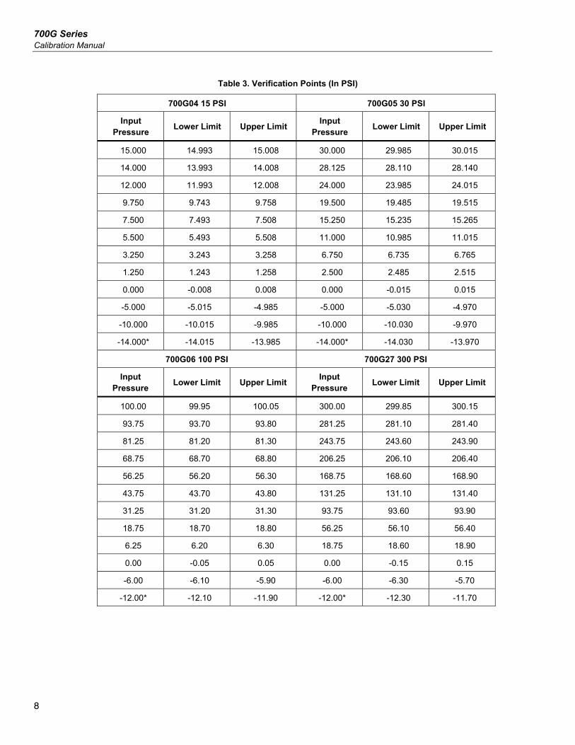
Table 3. Verification Points (In PSI)
700G04 15 PSI 700G05 30 PSI
Input Pressure
Lower Limit Upper Limit Input
Pressure Lower Limit Upper Limit
15.000 14.993 15.008 30.000 29.985 30.015
14.000 13.993 14.008 28.125 28.110 28.140
12.000 11.993 12.008 24.000 23.985 24.015
9.750 9.743 9.758 19.500 19.485 19.515
7.500 7.493 7.508 15.250 15.235 15.265
5.500 5.493 5.508 11.000 10.985 11.015
3.250 3.243 3.258 6.750 6.735 6.765
1.250 1.243 1.258 2.500 2.485 2.515
0.000 -0.008 0.008 0.000 -0.015 0.015
-5.000 -5.015 -4.985 -5.000 -5.030 -4.970
-10.000 -10.015 -9.985 -10.000 -10.030 -9.970
-14.000* -14.015 -13.985 -14.000* -14.030 -13.970
700G06 100 PSI 700G27 300 PSI
Input Pressure
Lower Limit Upper Limit Input
Pressure Lower Limit Upper Limit
100.00 99.95 100.05 300.00 299.85 300.15
93.75 93.70 93.80 281.25 281.10 281.40
81.25 81.20 81.30 243.75 243.60 243.90
68.75 68.70 68.80 206.25 206.10 206.40
56.25 56.20 56.30 168.75 168.60 168.90
43.75 43.70 43.80 131.25 131.10 131.40
31.25 31.20 31.30 93.75 93.60 93.90
18.75 18.70 18.80 56.25 56.10 56.40
6.25 6.20 6.30 18.75 18.60 18.90
0.00 -0.05 0.05 0.00 -0.15 0.15
-6.00 -6.10 -5.90 -6.00 -6.30 -5.70
-12.00* -12.10 -11.90 -12.00* -12.30 -11.70
Pressure Gauge Performance Verification Tests
9
Table 3. Verification Points (In PSI) (cont.)
700G07 500 PSI 700G08 1000 PSI
Input Pressure
Lower Limit Upper Limit Input
Pressure Lower Limit Upper Limit
500.00 499.75 500.25 1000.0 999.5 1000.5
468.75 468.50 469.00 937.5 937.0 938.0
406.25 406.00 406.50 812.5 812.0 813.0
343.75 343.50 344.00 687.5 687.0 688.0
281.25 281.00 281.50 562.5 562.0 563.0
218.75 218.50 219.00 437.5 437.0 438.0
156.25 156.00 156.50 312.5 312.0 313.0
93.75 93.50 94.00 187.5 187.0 188.0
31.25 31.00 31.50 62.5 62.0 63.0
0.00 -0.25 0.25 0.0 -0.5 0.5
-6.00 -6.50 -5.50
-12.00* -12.50 -11.50
700G29 3000 PSI 700G30 5000 PSI
Input Pressure
Lower Limit Upper Limit Input
Pressure Lower Limit Upper Limit
3000.0 2998.5 3001.5 5000.0 4997.5 5002.5
2812.5 2811.0 2814.0 4687.5 4685.0 4690.0
2437.5 2436.0 2439.0 4062.5 4060.0 4065.0
2062.5 2061.0 2064.0 3437.5 3435.0 3440.0
1687.5 1686.0 1689.0 2812.5 2810.0 2815.0
1312.5 1311.0 1314.0 2187.5 2185.0 2190.0
937.5 936.0 939.0 1562.5 1560.0 1565.0
562.5 561.0 564.0 937.5 935.0 940.0
187.5 186.0 189.0 312.5 310.0 315.0
0.0 -1.5 1.5 0.0 -2.5 2.5
700G Series Calibration Manual
10
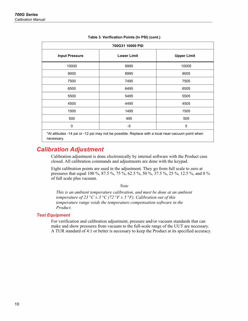
Table 3. Verification Points (In PSI) (cont.)
700G31 10000 PSI
Input Pressure Lower Limit Upper Limit
10000 9995 10005
9000 8995 9005
7500 7495 7505
6500 6495 6505
5500 5495 5505
4500 4495 4505
1500 1495 1505
500 495 505
0 -5 5
*At altitudes -14 psi or -12 psi may not be possible. Replace with a local near-vacuum point when necessary.
Calibration Adjustment Calibration adjustment is done electronically by internal software with the Product case closed. All calibration commands and adjustments are done with the keypad.
Eight calibration points are used in the adjustment. They go from full scale to zero at pressures that equal 100 %, 87.5 %, 75 %, 62.5 %, 50 %, 37.5 %, 25 %, 12.5 %, and 0 % of full scale plus vacuum.
Note
This is an ambient temperature calibration, and must be done at an ambient temperature of 23 °C ± 3 °C (72 °F ± 5 °F). Calibration out of this temperature range voids the temperature compensation software in the Product.
Test Equipment For verification and calibration adjustment, pressure and/or vacuum standards that can make and show pressures from vacuum to the full-scale range of the UUT are necessary. A TUR standard of 4:1 or better is necessary to keep the Product at its specified accuracy.
Pressure Gauge Calibration Adjustment
11
Connections The Product uses a ¼ inch NPT male connection in the pressure input port. Different adapters can be necessary to connect to the pressure standard. Always make sure the hose, tubing, and fittings. Have a rated working pressure at or above the pressure of the unit. It is also important that there be no leaks when you calibrate the Product. Use Teflon tape where necessary.
Enter Calibration Mode After you have made the connections, turn on the power while you hold . Use and to enter the password: 101 then push . If you went into calibration mode correctly, the display will show CAL. The pressure value shown will be the full-scale value of the Product. For Calibration points and their values, see Table 4.
Procedure Example
Note
This example uses a 700G07 Pressure Gauge (maximum pressure 500.00 psi). Apply the shown pressures necessary for your Product as shown in Table 4 .
The Product will prompt you for the necessary pressure at each calibration point.
1. Use the pressure standard to output 500.00 psi (100 %). After the output is stable, push to continue. As the Product measures, the screen will show ———-. When measurements are complete the screen will show the calibration value.
2. Use the pressure standard to output 437.50 psi (87.5 %). After the output is stable, push to continue. As the Product measures, the screen will show ———-. When measurements are complete the screen will show the calibration value.
3. Use the Pressure Standard to output 375.00 psi (75 %). After the output is stable, push to continue. As the Product measures, the screen will show ———-. When measurements are complete the screen will show the calibration value.
4. Use the Pressure Standard to output 312.50 psi (62.5 %). After the output is stable, push to continue. As the Product measures, the screen will show ———-. When measurements are complete the screen will show the calibration value.
5. Use the Pressure Standard to output 250.00 psi (50 %). After the output is stable, push to continue. As the Product measures, the screen will show ———-. When measurements are complete the screen will show the calibration value.
6. Use the Pressure Standard to output 187.50 psi (37.5 %). After the output is stable, push to continue. As the Product measures, the screen will show ———-. When measurements are complete the screen will show the calibration value.
7. Use the Pressure Standard to output 125.00 psi (25 %). After the output is stable, push to continue. As the Product measures, the screen will show ———-. When measurements are complete the screen will show the calibration value.
8. Use the Pressure Standard to output 62.50 psi (12.5 %). After the output is stable, push to continue. As the Product measures, the screen will show ———-. When measurements are complete the screen will show the calibration value.
9. Use the Pressure Standard to output 0.00 psi. After the output is stable, push to continue. As the Product measures, the screen will show ———-. When measurements are complete the screen will show the calibration value.
700G Series Calibration Manual
12
Note
Only some ranges use vacuum calibration. If your Product does not, then this step can be skipped and calibration is complete.
10. Use the Pressure Standard to output -12.00 psi. After the output is stable, push to continue. As the Product measures, the screen will show ———-. When the measurements are complete, a Product reset occurs and the Product turns off then turns on as usual.
Serial Interface Use terminal communication software on a PC to set up terminal communication. An RS-232 to USB cable is necessary. This cable comes with 700G/TRACK Software. Use these terminal parameters:
• Bits per second: 9600
• Data bits: 8
• Parity: None
• Stop bits: 1
• Flow control: None
• Local echo: on
Pressure Gauge Serial Interface
13
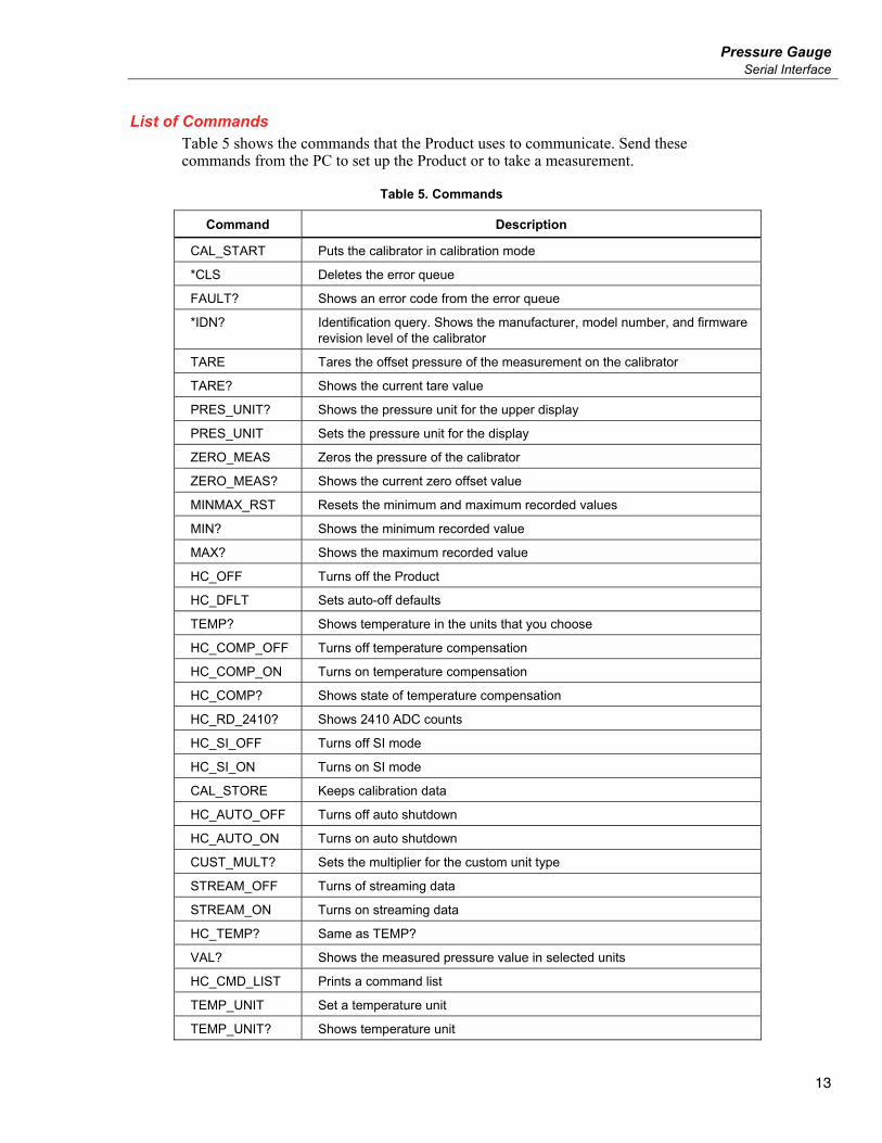
List of Commands Table 5 shows the commands that the Product uses to communicate. Send these commands from the PC to set up the Product or to take a measurement.
Table 5. Commands
Command Description
CAL_START Puts the calibrator in calibration mode
*CLS Deletes the error queue
FAULT? Shows an error code from the error queue
*IDN? Identification query. Shows the manufacturer, model number, and firmware revision level of the calibrator
TARE Tares the offset pressure of the measurement on the calibrator
TARE? Shows the current tare value
PRES_UNIT? Shows the pressure unit for the upper display
PRES_UNIT Sets the pressure unit for the display
ZERO_MEAS Zeros the pressure of the calibrator
ZERO_MEAS? Shows the current zero offset value
MINMAX_RST Resets the minimum and maximum recorded values
MIN? Shows the minimum recorded value
MAX? Shows the maximum recorded value
HC_OFF Turns off the Product
HC_DFLT Sets auto-off defaults
TEMP? Shows temperature in the units that you choose
HC_COMP_OFF Turns off temperature compensation
HC_COMP_ON Turns on temperature compensation
HC_COMP? Shows state of temperature compensation
HC_RD_2410? Shows 2410 ADC counts
HC_SI_OFF Turns off SI mode
HC_SI_ON Turns on SI mode
CAL_STORE Keeps calibration data
HC_AUTO_OFF Turns off auto shutdown
HC_AUTO_ON Turns on auto shutdown
CUST_MULT? Sets the multiplier for the custom unit type
STREAM_OFF Turns of streaming data
STREAM_ON Turns on streaming data
HC_TEMP? Same as TEMP?
VAL? Shows the measured pressure value in selected units
HC_CMD_LIST Prints a command list
TEMP_UNIT Set a temperature unit
TEMP_UNIT? Shows temperature unit
700G Series Calibration Manual
14
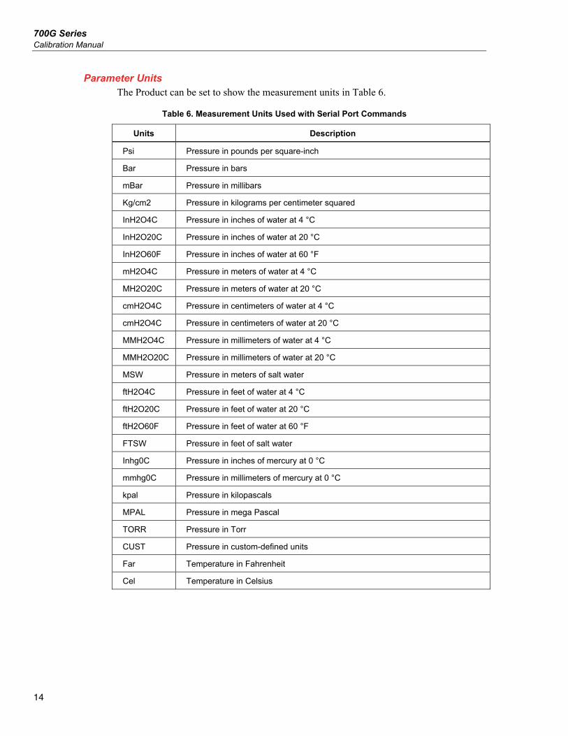
Parameter Units The Product can be set to show the measurement units in Table 6.
Table 6. Measurement Units Used with Serial Port Commands
Units Description
Psi Pressure in pounds per square-inch
Bar Pressure in bars
mBar Pressure in millibars
Kg/cm2 Pressure in kilograms per centimeter squared
InH2O4C Pressure in inches of water at 4 °C
InH2O20C Pressure in inches of water at 20 °C
InH2O60F Pressure in inches of water at 60 °F
mH2O4C Pressure in meters of water at 4 °C
MH2O20C Pressure in meters of water at 20 °C
cmH2O4C Pressure in centimeters of water at 4 °C
cmH2O4C Pressure in centimeters of water at 20 °C
MMH2O4C Pressure in millimeters of water at 4 °C
MMH2O20C Pressure in millimeters of water at 20 °C
MSW Pressure in meters of salt water
ftH2O4C Pressure in feet of water at 4 °C
ftH2O20C Pressure in feet of water at 20 °C
ftH2O60F Pressure in feet of water at 60 °F
FTSW Pressure in feet of salt water
Inhg0C Pressure in inches of mercury at 0 °C
mmhg0C Pressure in millimeters of mercury at 0 °C
kpal Pressure in kilopascals
MPAL Pressure in mega Pascal
TORR Pressure in Torr
CUST Pressure in custom-defined units
Far Temperature in Fahrenheit
Cel Temperature in Celsius
Pressure Gauge Replacement Parts and Accessories
15
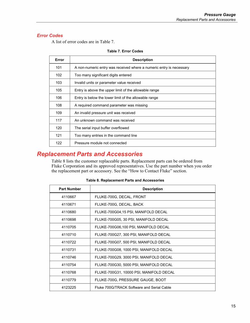
Error Codes A list of error codes are in Table 7.
Table 7. Error Codes
Error Description
101 A non-numeric entry was received where a numeric entry is necessary
102 Too many significant digits entered
103 Invalid units or parameter value received
105 Entry is above the upper limit of the allowable range
106 Entry is below the lower limit of the allowable range
108 A required command parameter was missing
109 An invalid pressure unit was received
117 An unknown command was received
120 The serial input buffer overflowed
121 Too many entries in the command line
122 Pressure module not connected
Replacement Parts and Accessories Table 8 lists the customer replaceable parts. Replacement parts can be ordered from Fluke Corporation and its approved representatives. Use the part number when you order the replacement part or accessory. See the “How to Contact Fluke” section.
Table 8. Replacement Parts and Accessories
Part Number Description
4110667 FLUKE-700G, DECAL, FRONT
4110671 FLUKE-700G, DECAL, BACK
4110680 FLUKE-700G04,15 PSI, MANIFOLD DECAL
4110698 FLUKE-700G05, 30 PSI, MANIFOLD DECAL
4110705 FLUKE-700G06,100 PSI, MANIFOLD DECAL
4110710 FLUKE-700G27, 300 PSI, MANIFOLD DECAL
4110722 FLUKE-700G07, 500 PSI, MANIFOLD DECAL
4110731 FLUKE-700G08, 1000 PSI, MANIFOLD DECAL
4110746 FLUKE-700G29, 3000 PSI, MANIFOLD DECAL
4110754 FLUKE-700G30, 5000 PSI, MANIFOLD DECAL
4110768 FLUKE-700G31, 10000 PSI, MANIFOLD DECAL
4110779 FLUKE-700G, PRESSURE GAUGE, BOOT
4123225 Fluke 700G/TRACK Software and Serial Cable