Piling and Pile Driving 332 2002 703.00 PILING AND PILE DRIVING (SSHC Section 703) A. The Department’s Geotechnical Section in the Materials and Research Division provides guidance and geotechnical designs for our projects. Some county bridge projects are completely designed by consultants including pile foundations. When a consultant design fails, i.e., bearing cannot be achieved, the consultant that designed the bridge should be the first point of contact to determine how to correct a failed design. 703.01 EQUIPMENT A. Diesel Hammers 1. Generally, single acting diesel hammers are the mainstay of contractors for pile driving. Occasionally however, a contractor will request the use of an "air" or "hydraulic" operated hammer. In addition there are a few "double acting" hammers in use. A wave equation analysis will be required for approval of these hammers. 2. One manufacturer of hammers uses one size hammer barrel and places different sized rams inside. Therefore, the MKT "DE" series hammers need to be field verified for ram mass (weight). A check is accomplished by having the contractor stand the hammer upright (in the driving position) and measuring down from top of the barrel to top of the ram. Verify the ram mass (weight) shown on the Hammer Data sheet as follows: Ram Mass (kg) Ram Distance (meter) Ram Mass (tons) Ram Distance (ft) 907 1.9 1 6.25 1270 1.2 1.4 4.0 1497 0.7 1.65 2.3 1814 180 mm 2.0 0.6 B. Bearing and Penetration 1. Penetration Requirements a. Design pile length is a calculated value based on design bearing and soil conditions. One factor which enters into the calculation is the potential for scour. Obviously, any soil which is eroded during a flood event represents a loss in bearing capacity and foundation stability. For this reason "minimum penetration" is extremely important. b. A depth of expected scour is typically shown on the Bridge Geology sheet in the plans. In general, streams with large drainage areas and sand or gravel stream beds are quite susceptible to scour while streams with small drainage areas and heavy clay stream beds are less susceptible to scour. c. When doubt exists concerning the amount of probable scour or minimum pile penetration required, the Construction Division should be consulted. If greater penetration is required, it will be achieved either by boring holes to receive the piles or by jetting. If penetration achieved is satisfactory, piles will be cut off.
Transcript
Piling and Pile Driving
332 2002
703.00 PILING AND PILE DRIVING (SSHC Section 703) A. The Department’s Geotechnical Section in the Materials and Research Division provides
guidance and geotechnical designs for our projects. Some county bridge projects are completely designed by consultants including pile foundations. When a consultant design fails, i.e., bearing cannot be achieved, the consultant that designed the bridge should be the first point of contact to determine how to correct a failed design.
703.01 EQUIPMENT A. Diesel Hammers
1. Generally, single acting diesel hammers are the mainstay of contractors for pile driving. Occasionally however, a contractor will request the use of an "air" or "hydraulic" operated hammer. In addition there are a few "double acting" hammers in use. A wave equation analysis will be required for approval of these hammers.
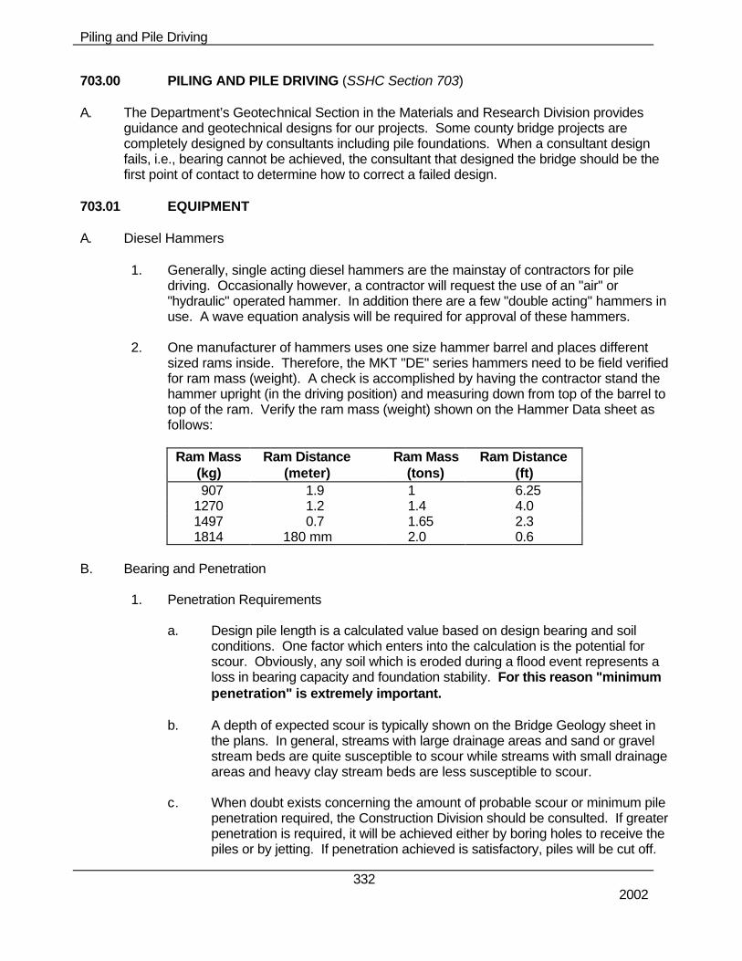
2. One manufacturer of hammers uses one size hammer barrel and places different
sized rams inside. Therefore, the MKT "DE" series hammers need to be field verified for ram mass (weight). A check is accomplished by having the contractor stand the hammer upright (in the driving position) and measuring down from top of the barrel to top of the ram. Verify the ram mass (weight) shown on the Hammer Data sheet as follows:
a. Design pile length is a calculated value based on design bearing and soil conditions. One factor which enters into the calculation is the potential for scour. Obviously, any soil which is eroded during a flood event represents a loss in bearing capacity and foundation stability. For this reason "minimum penetration" is extremely important.
b. A depth of expected scour is typically shown on the Bridge Geology sheet in
the plans. In general, streams with large drainage areas and sand or gravel stream beds are quite susceptible to scour while streams with small drainage areas and heavy clay stream beds are less susceptible to scour.
c. When doubt exists concerning the amount of probable scour or minimum pile
penetration required, the Construction Division should be consulted. If greater penetration is required, it will be achieved either by boring holes to receive the piles or by jetting. If penetration achieved is satisfactory, piles will be cut off.
Piling and Pile Driving
333 2002
C. Dynamic Pile Analyzer
1. The Materials & Research Division has a pile analyzer available for driving evaluations. The pile analyzer will evaluate the bearing, based on energy delivered to a pile as it is being driven.
2. There are two situations where the analyzer should be used:
Case 1. Contract documents require pile to be driven with the analyzer. Case 2. Pile do not achieve bearing and there are unresolvable questions or
conditions observed during driving.
703.02 CONSTRUCTION METHODS A. Pile Driving Constraints
1. Piles shall not be driven within 50 ft (15 m) of freshly placed concrete. Normally piles
may not be driven near new concrete until three days after the concrete was placed.
B. Splicing Pile--Welding Steel Pile
1. SSHC Section 708 requires that all welds conform to the Structural Welding Code ANSI/AASHTO/AWS DI.5 of the American Welding Society.
2. Only Shielded Metal Arc Welding (SMAW) will be permitted for welding steel piles. 3. The welding electrode must be on the NDR Approved Products List.
C. Steel Pile Cutoffs
1. If the contractor feels the cutoff is long enough that they may use it on some future project, the Heat number should be placed on the cutoff and a number to indicate the project it came from.
D. Pile Groups/Categories
1. Selecting the type of pile to be used and estimating its necessary length are fairly difficult tasks that require good judgment.
2. Piles can be divided into two major groups, depending on their length and the
mechanisms of load transfer to the soil:
a. Point Bearing Piles
(1) If bedrock is within a reasonable depth, then piles can be extended to the rock and achieve the ultimate bearing capacity.
b. Friction Piles
Piling and Pile Driving
334 2002
(1) The ultimate bearing capacity is achieved through the skin friction. The length of friction piles depends on the shear strength of the soil, the applied load and pile size. In clayey soils, the resistance to applied load is caused by adhesion.
(2) Piles are also divided into two different categories depending on their
interaction with the soil:
c. Displacement Pile:
(1) The effect of displacement pile on the soil is, it increases the lateral ground stress. It displaces cohesion-less soils, remolds and weakens cohesive soils temporarily. If displacement piles are used for cohesive soil, setup time in sensitive clays may be up to six months.
(2) Typical types of displacement piles are closed end steel pipe pile and
concrete pile.
d. Non-displacement Pile:
(1) Opposite of the displacement pile, it minimizes disturbance to the soil. (2) Typical types of non-displacement piles are open-end steel pile and
steel H pile. It should be mentioned open steel pipe is not suited for friction piles in coarse granular soils.
(3) It has low driving resistance and this makes field capacity verification
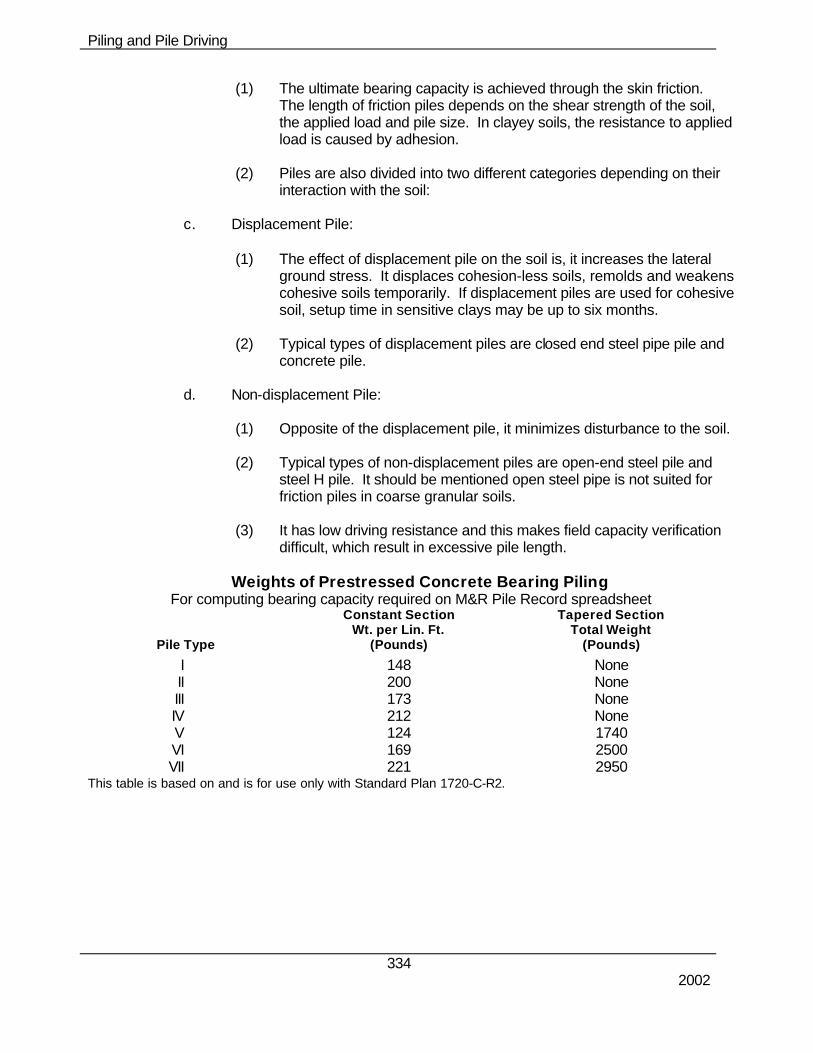
difficult, which result in excessive pile length. Weights of Prestressed Concrete Bearing Piling
For computing bearing capacity required on M&R Pile Record spreadsheet
Pile Type
Constant Section Wt. per Lin. Ft.
(Pounds)
Tapered Section Total Weight
(Pounds)
I 148 None II 200 None III 173 None IV 212 None V 124 1740 VI 169 2500 VII 221 2950 This table is based on and is for use only with Standard Plan 1720-C-R2.
Piling and Pile Driving
335 2002
Steel Pipe Pile Data ARMCO Union Metal
Size O.D. (ins) 12 12¾ 12 (Nominal) Wall T. (ins.) .188 .188 7 Ga. Wt. per Lin. Ft. (lbs.) 23.72 25.16 25.3 Conc. per Lin. Ft. (C.Y.) .0273 .0309 .0255
Union Metal 30’ tapered Sec. Type F Total Wt. 589 Lbs. Conc. 0.55 Cu. Yd.
Size O.D. (ins) 14 14 (Nominal) Wall T. (ins.) .188 7 Ga. Wt. per Lin. Ft. (lbs.) 27.66 29.5 Conc. per Lin. Ft. (C.Y.) .0375 .0350
Union Metal 40’ tapered Sec. Type F Total Wt. 895 Lbs. Conc. 0.95 Cu. Yd.
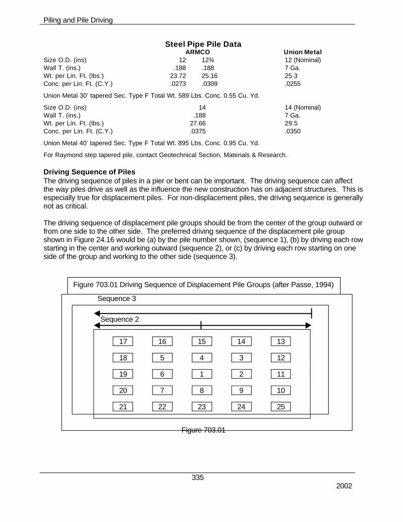
For Raymond step tapered pile, contact Geotechnical Section, Materials & Research. Driving Sequence of Piles The driving sequence of piles in a pier or bent can be important. The driving sequence can affect the way piles drive as well as the influence the new construction has on adjacent structures. This is especially true for displacement piles. For non-displacement piles, the driving sequence is generally not as critical. The driving sequence of displacement pile groups should be from the center of the group outward or from one side to the other side. The preferred driving sequence of the displacement pile group shown in Figure 24.16 would be (a) by the pile number shown, (sequence 1), (b) by driving each row starting in the center and working outward (sequence 2), or (c) by driving each row starting on one side of the group and working to the other side (sequence 3).
17 16 15 14 13
18 5 4 3 12
19 6 1 2 11
20 7 8 9 10
21 22 23 24 25
Figure 703.01
Sequence 2
Sequence 3
Figure 703.01 Driving Sequence of Displacement Pile Groups (after Passe, 1994)
Piling and Pile Driving
336 2002
The following guidelines for Single Acting Diesel Hammer are provided to assist you. If there is a need for a different type of hammer inspection guideline, please contact the Geotechnical Section. It is very important to field check the hammer systems provided by the contractor to the hammer data sheets after they are approved by the Geotechnical Section. Prior to pile driving, please verify cap weight and size and condition of the hammer cushion material as shown on the hammer data sheets.
E. Inspection of Piles Prior to and During Installation
1. The inspection will be different for each type of pile. Shop plans are required for sheet piles, but usually are not required for H-piles, concrete-piles or pipe-piles.
2. When MSE walls are being constructed, at times the soil conditions may require
additional considerations. A note is sometimes included on our plans that states the MSE Wall Must Be Built Before Piles Are Driven. This note is usually applicable when the embankment behind the MSE wall is constructed as a fill. The note also usually specifies that the MSE wall cannot be constructed until the embankment has reached 95+% of its anticipated settlement. The concern here is that the granular backfill material will settle further and the embankment is also able to settle some additional amount due to the granular backfill load. The combined effect on the piling is to cause a downward load on the piling that will reduce the piling’s capacity to resist the live and dead loads from the roadway.
3. Battered piles are driven at 1 ft. offset per 12 ft. of length or 3.33 ft. offset in 40 ft.
F. Precast Concrete Piles
1. The following is a list of items for prestressed concrete piles to be inspected at the construction site:
a. The piles should be of the specified length and section. The inspector must
be assured that a minimum concrete strength has been obtained. If the piles are to be spliced on the site, the splices should meet the specified requirements (type, alignment, etc.).
b. Piles should be inspected for cracks or spalling. There should be no evidence
that any pile has been damaged during shipping to the site, or during unloading of piles at the site. Lifting hooks are generally cast into the piling at pick-up points. Piles should be unloaded by properly sized and tensioned slings attached to each lifting hook.
c. The piles should be stored properly. When piles are being placed in storage,
they should be stored above ground on adequate blocking in a manner which keeps them straight and prevents undue bending stresses.
d. The contractor should lift the piles into the leads properly and safely. Cables
looped around the pile are satisfactory for lifting. Chain slings should never be permitted. Cables should be of sufficient strength and be in good condition. Frayed cables are unacceptable and should be replaced. For shorter piles, a
Piling and Pile Driving
337 2002
single pick-up point may be acceptable. The pick-up point locations should be as specified by the casting yard. For longer piles, two or more pick-up points at designated locations may be required.
e. The pile should be free to twist and move laterally in the helmet. f. Piles should have no noticeable cracks when placed in leads or during
installation. Spalling of the concrete at the top or near splices should not be evident.
g. Steel H-Piles
1. The following should be inspected at the construction site:
a. The piles being driven must be oriented with flanges in the correct direction as shown on the plans. Because the lateral resistance to bending of H-piles is considerably more in the direction perpendicular to flanges, the correct orientation of H-piles is very important.
b. The piles should be of the specified steel grade, length, or section/weight. c. Pile points, if required for pile toe protection, should be as specified. d. Splices should be either proprietary splices or full penetration groove welds as
specified. The top and bottom pile sections should be in good alignment before splicing.
e. Pile point attachments and splices must be welded properly. f. There should be no observable pile damage, including deformations at the pile
head. G. Steel Pipe Piles
1. The following should be inspected at the construction site:
a. The piles should be of specified steel grade, length, or minimum section/weight (wall thickness) and either seamless or spiral welded as specified.
b. Piles should be driven either open-ended or closed-ended. Closed-ended
pipe piles should have bottom closure plates or conical points of the correct size (diameter and thickness) and be welded on properly, as specified. Open-end pipe piles should have cutting shoes that are welded on properly.
c. The top and bottom pile sections should be in good alignment before splicing.
Splices or full penetration groove welds should be installed as specified. d. There should be no observable pile damage, including deformations at the pile
head. After installation, closed-end pipes should be visually inspected for damage or water prior to filling with concrete.
Piling and Pile Driving
338 2002
H. Steel Sheet Piles
1. The sheet piles must meet thickness, section models, steel grade, length and width requirements as shown in our plans.
2. Sheet pile length should be measured so that analysis of obstructions to driving can be properly accomplished.
3. Sheet piles should be driven plumb or at the angle shown in the plans. I. Inspection of Driving Equipment
A typical driving system consists of crane, leads, hammer, hammer cushion, helmet, and in the case of concrete piles, a pile cushion. Each component of the drive system has a specific function and plays an important role in the pile installation. The project plans and specifications may specify or restrict certain items of driving equipment. The Geotechnical Section will approve the contractor’s driving equipment and determine conformity with the plans and specifications. The inspector must be sure the equipment used is what was approved.
1. The following checklist will be useful in the inspection of driving equipment before
driving:
a. The pile driving hammer should be the specified type/size.
(1) The inspector should make sure for single acting air/steam or hydraulic hammers that the contractor uses the proper size external power source and that, for adjustable stroke hammers, the stroke necessary for the required energy be obtained. For double acting or differential air/steam or hydraulic hammers, the contractor must again obtain the proper size external power source and the operating pressure and volume must meet the hammer manufacturer’s specification.
b. The hammer cushion being used should be checked to confirm it is of the
approved material type, size and thickness.
(1) The main function of the hammer cushion is to protect the hammer itself from fatigue and high frequency accelerations which would result from steel to steel impact with the helmet and/or pile. The hammer cushion should have the proper material and same shape/area to snugly fit inside the helmet (drive cap). If the cushion diameter is too small, the cushion will break or badly deform during hammer blows and become ineffective. The hammer cushion must not be excessively deformed or compressed. Some air/steam hammers rely upon a certain total thickness (of cushion plus striker plate) for proper valve timing. Hammers with incorrect hammer cushion thickness may not operate, or will have improper kinetic energy at impact. Since it is difficult to inspect this item once the driving operation begins, it should be checked before the contractor starts pile driving on a project as well as periodically during production driving on larger projects.
Piling and Pile Driving
339 2002
c. The helmet (drive cap) should properly fit the pile.
(1) The purpose of the helmet is to hold the pile head in alignment and transfer the impact concentrically from the hammer to the pile. The helmet also houses the hammer cushion, and must accommodate the pile cushion thickness for concrete piles. The helmet should fit loosely to avoid transmission of torsion or bending forces, but not so loosely as to prevent the proper alignment of hammer and pile. Helmets should ideally be of roughly similar size to the pile diameter. Although generally discouraged, spacers may be used to adapt an oversize helmet, provided the pile will still be held concentrically wit the hammer. A properly fitting helmet is important for all pile types, but is particularly critical for precast concrete piles. A poorly fitting helmet often results in pile head damage. Check and record the helmet weight for conformance to wave equation analysis or for future wave equation analysis. Larger weights will reduce the energy transfer to the pile.
d. The pile cushion should be of correct type material and thickness for concrete piles.
(1) The purpose of the pile cushion is to reduce high compression stresses, to evenly distribute the applied forces to protect the concrete pile head from damage, and to reduce the tension stresses in easy driving. Pile cushions for concrete piles should have the required thickness determined from a wave equation analysis but not less than 4 inches (100 mm). A new plywood, hardwood, or composite wood pile cushion, which is not water soaked, should be used for every pile. The cushion material should be checked periodically for damage and replaced before excessive compression (more than half the original thickness), burning or charring occurs. Wood cushions may take only about 1,000 to 2,000 blows before they deteriorate. During hard driving, more than one cushion may be necessary for a single pile. Longer piles or piles driven with larger hammers may require thicker pile cushions.
e. Predrilling, jetting or spudding equipment, if specified or permitted, should be available for use and meet the requirements. The depth of predrilling, jetting or spudding should be very carefully controlled so that it does not exceed the allowable limits, usually 10 feet (1 m). Predrilling, jetting, or spudding below the allowed depths will generally result in a reduced pile capacity, and the pile acceptance may become questionable.
f. A lead system must be used.
(1) The leads perform the very important function of holding the hammer and pile in good alignment with each other. Poor alignment reduces energy transfer as some energy is then imparted into horizontal motion. Poor alignment also generally results in higher bending stresses and higher local contact stresses which can cause pile damage. This is particularly important at end of driving when driving resistance is highest and driving stresses are generally increased.
Piling and Pile Driving
340 2002
J. Inspection of Driving Equipment During Installation
1. The main purpose of inspection is to assure that piles are installed so that they meet the driving criteria and the pile remains undamaged. The driving criteria is often defined as a minimum driving resistance as measured by the blow count in blows per inch. The driving criteria is to assure that piles have the desired capacity. However, the driving resistance is also dependent upon the performance of the pile driving hammer. The driving resistance will generally be lower when the hammer imparts higher energy and force to the pile, and the driving resistance will be higher if the hammer imparts lower energy and force to the pile. High driving resistances can be due either to soil resistance or to a poorly performing hammer. Thus, for the inspector to assure that the minimum driving criteria has been met and, therefore, the capacity is adequate, the inspector must evaluate if the hammer is performing properly.
2. Each hammer has its own operating characteristics; the inspector should not blindly
assume that the hammer on the project is in good working condition. In fact, two different types of hammers with identical energy rating will not drive the same pile in the same soil with the same driving resistance. In fact, two supposedly identical hammers (same make and model) may not have similar driving capability due to several factors including differing friction losses, valve timing, air supply hose type-length-condition, duel type and intake amount, and other maintenance status items. The inspector should become familiar with the proper operation of the hammer(s) used on site. The inspector may wish to contact the hammer manufacturer or supplier who generally will welcome the opportunity to supply further information.
K. Single Acting Diesel Hammers
1. Determine/confirm that the hammer is the correct make and model. Check for and record any identifying labels as to hammer make, model and serial number.
2. Make sure all exhaust ports are open with all plugs removed. 3. Inspect the recoil dampener for condition and thickness. If excessively worn or
improper thickness (consult manufacturer) it should be replaced. If the recoil dampener is too thin, the stroke will be reduced. If it is too thick, or if cylinder does not rest on dampener between blows, the ram could blow out the hammer top and become a safety hazard.
4. Check that lubrication of all grease nipples is regularly made. Most manufacturers
recommend the impact block be greased every half-hour of operation. 5. As the ram is visible between blows, check the ram for signs of uniform lubrication
and ram rotation. Poor lubrication will increase friction and reduce energy to the pile.
Piling and Pile Driving
341 2002
6. Determine the hammer stroke, especially at end of driving or beginning of restrike. A “jump stick” attached to the cylinder is a safety hazard and should not be used. The stroke can be determined by a saximeter which measures the time between blows and then calculates the stroke. The hammer stroke can also be calculated from this formula if the number of blows per minute (bpm) is manually recorded.
h [meters] = (4400/[bpm2]) – 0.90
a. The calculated stroke may require correction for batter or inclined piles. The
inspector should always observe the ram rings and visually estimate the stroke using the manufacturer’s chart.
7. As the driving resistance increases, the stroke should also increase. At the end of
driving, if the ram fails to achieve the correct stroke (part of the driving criteria from a wave equation analysis), the cause could be lack of fuel. Most hammers have adjustable fuel pumps. Some have distinct fuel settings, others are continuously variable, and some use a pressure pump. Make sure the pump is on the correct fuel setting or pressure necessary to develop the required stroke. The fuel and fuel line should be free of dirt or other contaminants. A clogged or defective fuel injector will also reduce the stroke and should be replaced if needed.
8. Low strokes could be due to poor compression caused by worn or defective piston or
anvil rings. Check compression by raising the ram, and with the fuel turned off, allowing the ram to fall. The ram should bounce several times if the piston and anvil rings are satisfactory.
9. Watch for signs of preignition. When a hammer preignites, the fuel burns before
impact, requiring extra energy to compress gas and leaving less energy to transfer to the pile. In long sustained periods of driving, or if the wrong fuel with a low flash point is used, the hammer could overheat and preignite. When preignition occurs, less energy is transferred and the driving resistance rises, giving a false indication of high pile capacity. If piles driven with a cold hammer drive deeper or with less hammer blows, or if the driving resistances decrease after short breaks, preignition could be the cause and should be investigated. Dynamic testing is the preferable method to check for preignition.
10. For some diesel hammers, the total thickness of hammer cushion and striker plate
must match the hammer manufacturer’s recommendation and the hammer cushion cavity in the helmet for proper fuel injection and hammer operation. This total thickness must be maintained.
11. Make sure the helmet stays properly seated on the pile and that the hammer and pile
maintain alignment during operation. 12. The hammer hoist line should always be slack, with the hammer’s weight fully carried
by the pile. Excessive tension in the hammer hoist line is a safety hazard and will reduce energy to the pile. Leads should always be used.
Piling and Pile Driving
342 2002
13. Some manufacturers void their warranty if the hammer is consistently operated
above 100 blows per 250 mm of penetration beyond short periods, such as those required when toe bearing piles are driven to rock. Therefore, in prolonged hard driving situations, it may be more desirable to use a larger hammer or stiffer pile section.
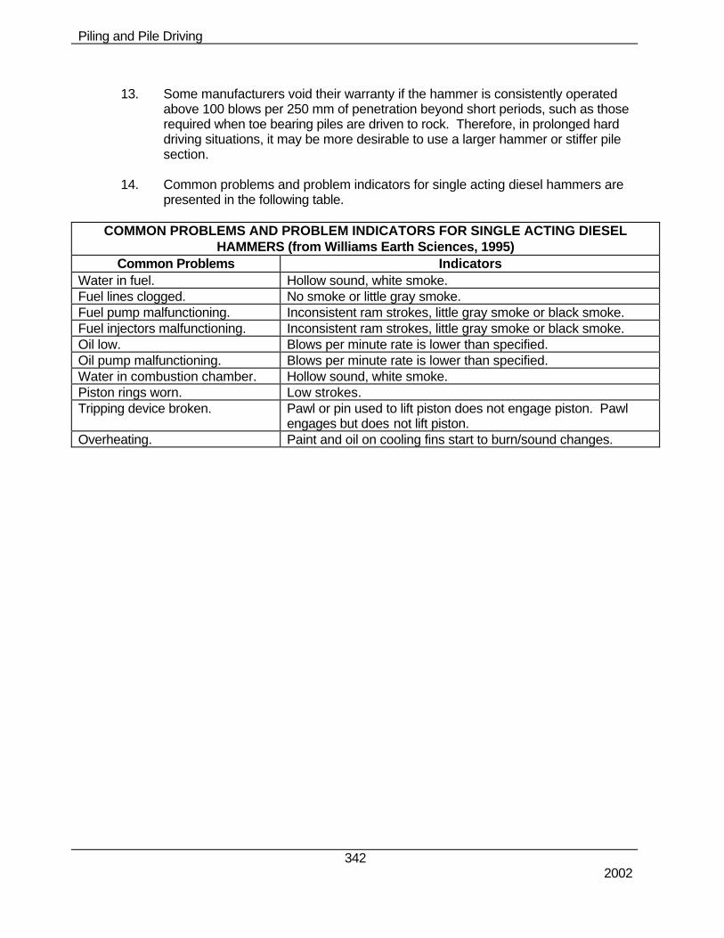
14. Common problems and problem indicators for single acting diesel hammers are
presented in the following table.
COMMON PROBLEMS AND PROBLEM INDICATORS FOR SINGLE ACTING DIESEL HAMMERS (from Williams Earth Sciences, 1995)
Common Problems Indicators Water in fuel. Hollow sound, white smoke. Fuel lines clogged. No smoke or little gray smoke. Fuel pump malfunctioning. Inconsistent ram strokes, little gray smoke or black smoke. Fuel injectors malfunctioning. Inconsistent ram strokes, little gray smoke or black smoke. Oil low. Blows per minute rate is lower than specified. Oil pump malfunctioning. Blows per minute rate is lower than specified. Water in combustion chamber. Hollow sound, white smoke. Piston rings worn. Low strokes. Tripping device broken. Pawl or pin used to lift piston does not engage piston. Pawl
engages but does not lift piston. Overheating. Paint and oil on cooling fins start to burn/sound changes.
Piling and Pile Driving
343 2002
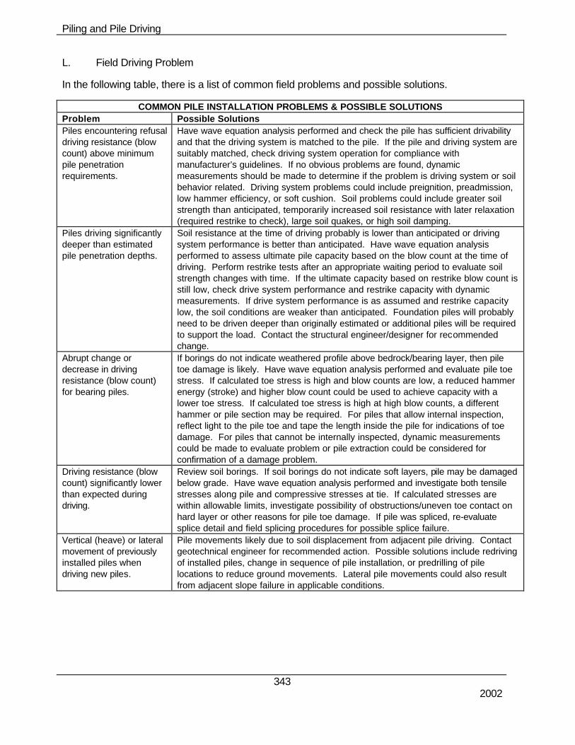
L. Field Driving Problem
In the following table, there is a list of common field problems and possible solutions.
COMMON PILE INSTALLATION PROBLEMS & POSSIBLE SOLUTIONS Problem Possible Solutions Piles encountering refusal driving resistance (blow count) above minimum pile penetration requirements.
Have wave equation analysis performed and check the pile has sufficient drivability and that the driving system is matched to the pile. If the pile and driving system are suitably matched, check driving system operation for compliance with manufacturer’s guidelines. If no obvious problems are found, dynamic measurements should be made to determine if the problem is driving system or soil behavior related. Driving system problems could include preignition, preadmission, low hammer efficiency, or soft cushion. Soil problems could include greater soil strength than anticipated, temporarily increased soil resistance with later relaxation (required restrike to check), large soil quakes, or high soil damping.
Piles driving significantly deeper than estimated pile penetration depths.
Soil resistance at the time of driving probably is lower than anticipated or driving system performance is better than anticipated. Have wave equation analysis performed to assess ultimate pile capacity based on the blow count at the time of driving. Perform restrike tests after an appropriate waiting period to evaluate soil strength changes with time. If the ultimate capacity based on restrike blow count is still low, check drive system performance and restrike capacity with dynamic measurements. If drive system performance is as assumed and restrike capacity low, the soil conditions are weaker than anticipated. Foundation piles will probably need to be driven deeper than originally estimated or additional piles will be required to support the load. Contact the structural engineer/designer for recommended change.
Abrupt change or decrease in driving resistance (blow count) for bearing piles.
If borings do not indicate weathered profile above bedrock/bearing layer, then pile toe damage is likely. Have wave equation analysis performed and evaluate pile toe stress. If calculated toe stress is high and blow counts are low, a reduced hammer energy (stroke) and higher blow count could be used to achieve capacity with a lower toe stress. If calculated toe stress is high at high blow counts, a different hammer or pile section may be required. For piles that allow internal inspection, reflect light to the pile toe and tape the length inside the pile for indications of toe damage. For piles that cannot be internally inspected, dynamic measurements could be made to evaluate problem or pile extraction could be considered for confirmation of a damage problem.
Driving resistance (blow count) significantly lower than expected during driving.
Review soil borings. If soil borings do not indicate soft layers, pile may be damaged below grade. Have wave equation analysis performed and investigate both tensile stresses along pile and compressive stresses at tie. If calculated stresses are within allowable limits, investigate possibility of obstructions/uneven toe contact on hard layer or other reasons for pile toe damage. If pile was spliced, re-evaluate splice detail and field splicing procedures for possible splice failure.
Vertical (heave) or lateral movement of previously installed piles when driving new piles.
Pile movements likely due to soil displacement from adjacent pile driving. Contact geotechnical engineer for recommended action. Possible solutions include redriving of installed piles, change in sequence of pile installation, or predrilling of pile locations to reduce ground movements. Lateral pile movements could also result from adjacent slope failure in applicable conditions.
Piling and Pile Driving
344 2002
COMMON PILE INSTALLATION PROBLEMS & POSSIBLE SOLUTIONS Problem Possible Solutions Piles driving out of alignment tolerance.
Piles may be moving out of alignment tolerance due to hammer-pile alignment control or due to soil conditions. If due to poor hammer-pile alignment control, a pile gate, template or fixed lead system may improve the ability to maintain alignment tolerance. Soil conditions such as near surface obstructions (see subsequent section) or steeply sloping bedrock having minimal overburden material (pile point detail is important) may prevent tolerance from being met even with good alignment control. In these cases, survey the as-built condition and contact the Geotechnical engineer for recommended action.
Piles driving out of location tolerance.
Piles may be moving out of location tolerance due to hammer-pile alignment control or due to soil conditions. If due to poor hammer-pile alignment control, a pile gate, template or fixed lead system may improve the ability to maintain location tolerance. Soil conditions such as near surface obstructions (see subsequent section) or steeply sloping bedrock having minimal overburden material (pile point detail is important) may prevent tolerances from being met even with good alignment control. In these cases, survey the as-built condition and contact the Geotechnical engineer for recommended action.
Piles encountering shallow obstructions.
If obstructions are within 3 feet of working grade, obstruction excavation and removal is probably feasible. If obstructions are at deeper depth, are below the water table, or the soil is contaminated, excavation may not be feasible. Spudding or predrilling of pile locations may provide a solution with method selection based on the type of obstructions and soil conditions.
Pile encountering obstructions at depth.
If deep obstructions are encountered that prevent reaching the desired pile penetration depth, contact the structural engineer/designer for remedial design. Ultimate capacity of piles hitting obstructions should be reduced based upon pile damage potential and soil matrix support characteristics. Additional foundation piles may be necessary.
Concrete piles develop partial horizontal cracks in easy driving.
Check hammer-pile alignment since bending may be causing the problem. If the alignment appears to be normal, tension and bending combined may be too high. The possible solution is as above with complete cracks.
Concrete pile spalling or slabbing near pile head.
Have Geotechnical Section determine pile head stress for observed blow count and compare with allowable stresses. If high calculated stress, add pile cushioning. If low calculated stress, investigate pile quality, hammer performance, hammer-pile alignment.
Concrete piles develop complete horizontal cracks in easy driving.
Have Geotechnical Section determine tension stresses along pile for observed blow counts. If high calculated tension stresses, add cushioning or reduce stroke. If low calculated tension stresses, check hammer performance and/or perform measurements.
Concrete piles develop complete horizontal cracks in hard driving.
Have Geotechnical Section determine tension stresses along pile. If high calculated tension stresses, consider heavier ram. If low calculated tension stresses, take measurements and determine quakes which are probably higher than anticipated.
Concrete piles develop partial horizontal cracks in easy driving.
Check hammer-pile alignment since bending may be the problem. If alignment appears to be normal, tension and bending combined may be too high; solution will then be the same as for complete cracks above.
Steel pile head deforms, timber pile top mushrooms.
Check helmet size/shape; check steel strength; check evenness of pile head, banding of timber pile head. If okay, have Geotechnical Section determine pile head stress. If calculated stress is high, reduce hammer energy (stroke) for low blow counts; for high blow counts, different hammer or pile type may be required.
Unexpectedly low blow counts during pile driving.
Investigate soil borings; if soil borings do not indicate soft layers, pile may be damaged below grade. Have Geotechnical Section investigate both tensile stresses along pile and compressive stresses at toe. If calculated stresses are acceptable, investigate possibility of obstructions/uneven toe contact on hard layer or other reasons for pile toe damage.
Piling and Pile Driving
345 2002
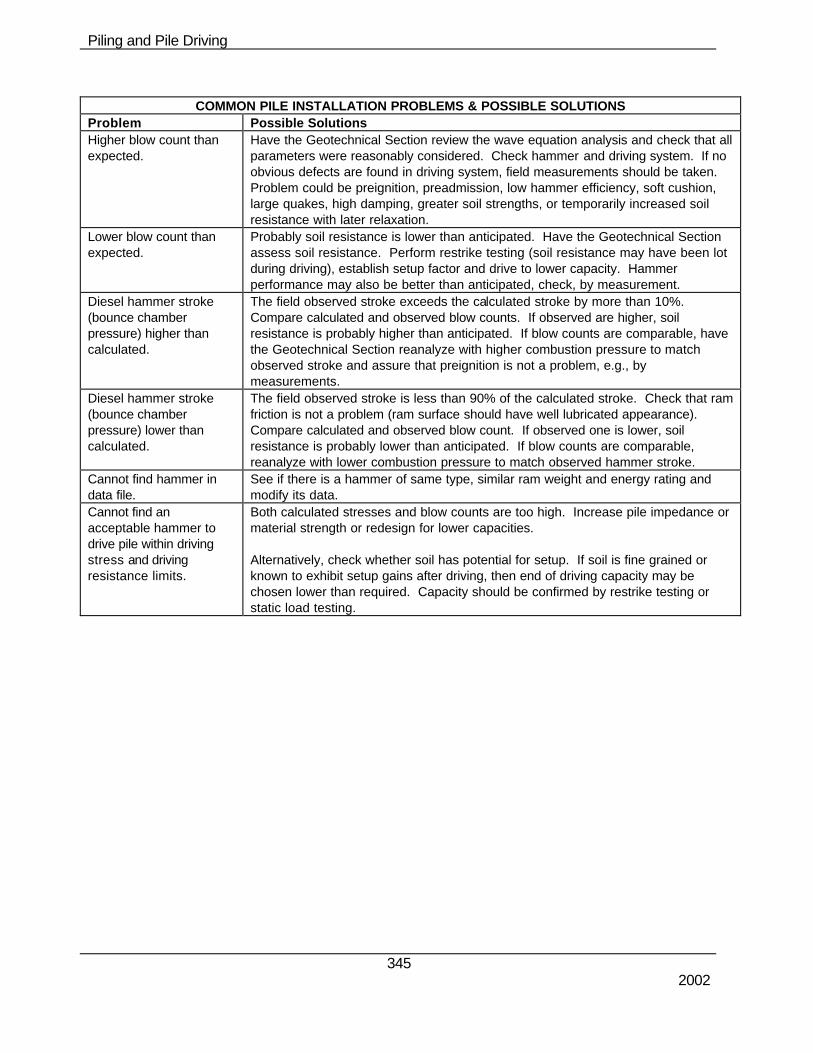
COMMON PILE INSTALLATION PROBLEMS & POSSIBLE SOLUTIONS
Problem Possible Solutions Higher blow count than expected.
Have the Geotechnical Section review the wave equation analysis and check that all parameters were reasonably considered. Check hammer and driving system. If no obvious defects are found in driving system, field measurements should be taken. Problem could be preignition, preadmission, low hammer efficiency, soft cushion, large quakes, high damping, greater soil strengths, or temporarily increased soil resistance with later relaxation.
Lower blow count than expected.
Probably soil resistance is lower than anticipated. Have the Geotechnical Section assess soil resistance. Perform restrike testing (soil resistance may have been lot during driving), establish setup factor and drive to lower capacity. Hammer performance may also be better than anticipated, check, by measurement.
Diesel hammer stroke (bounce chamber pressure) higher than calculated.
The field observed stroke exceeds the calculated stroke by more than 10%. Compare calculated and observed blow counts. If observed are higher, soil resistance is probably higher than anticipated. If blow counts are comparable, have the Geotechnical Section reanalyze with higher combustion pressure to match observed stroke and assure that preignition is not a problem, e.g., by measurements.
Diesel hammer stroke (bounce chamber pressure) lower than calculated.
The field observed stroke is less than 90% of the calculated stroke. Check that ram friction is not a problem (ram surface should have well lubricated appearance). Compare calculated and observed blow count. If observed one is lower, soil resistance is probably lower than anticipated. If blow counts are comparable, reanalyze with lower combustion pressure to match observed hammer stroke.
Cannot find hammer in data file.
See if there is a hammer of same type, similar ram weight and energy rating and modify its data.
Cannot find an acceptable hammer to drive pile within driving stress and driving resistance limits.
Both calculated stresses and blow counts are too high. Increase pile impedance or material strength or redesign for lower capacities. Alternatively, check whether soil has potential for setup. If soil is fine grained or known to exhibit setup gains after driving, then end of driving capacity may be chosen lower than required. Capacity should be confirmed by restrike testing or static load testing.