Bridges (Steel Structures) 347 2002 704.00 BRIDGES (STEEL STRUCTURES) (SSHC Section 708) 704.01 DESCRIPTION A. This work includes the furnishing, preparing and erecting of all riveted, bolted or welded structures in which the main members spanning the supports are composed of steel. 704.02 MATERIAL REQUIREMENTS A. Members of steel structures that are fabricated in the shop are inspected by NDR personnel before they are shipped to the job site. In some cases, when the fabrication is done outside of the state, the inspection will take place after delivery to the site of work. The Project Manager should have a copy of the shop inspection report and the mill test report before allowing the erection of any portion of the structure. Miscellaneous parts of the superstructure such as high tensile steel bolts will require field inspection and sampling according to the "Materials Sampling Guide". B. Field welding may require the use of special welding electrodes as designated in the plans, specifications, or special provisions. Some of these welding electrodes may require special care and handling before their use will be permitted. (See SSHC Section 708.) Enter date steel is verified in SiteManager. Occasionally wrong size is delivered. C. Concrete Industries rebar shipments will be documented to show bending details, heat numbers, quantity and project location by stationing. 704.03 CONSTRUCTION METHODS A. Falsework (SSHC Subsection 704.03) 1. Girders should be blocked so that the weight of any deck overhang does not bend the girder, which will ripple the deck. B. Temporary Fastenings 1. Contractors often request permission to use anchor supports for face forms, concrete curbs, Jersey barriers, raised medians on bridges. Any contractor desiring to use a temporary floor fastening may be allowed to use only some form of weakened section bolt or tie, cast in the floor. The weakened section must be so positioned that when broken off the break will be recessed below the surface. The resulting void must be patched with mortar. 2. NOTE: a. No bolt without a weakened section may be used. b. No holddown device shot into the floor will be allowed. (1) Concrete arch bridges. (2) Support of girders or other large structural elements when required.
A. This work includes the furnishing, preparing and erecting of all riveted, bolted or welded
structures in which the main members spanning the supports are composed of steel. 704.02 MATERIAL REQUIREMENTS A. Members of steel structures that are fabricated in the shop are inspected by NDR
personnel before they are shipped to the job site. In some cases, when the fabrication is done outside of the state, the inspection will take place after delivery to the site of work. The Project Manager should have a copy of the shop inspection report and the mill test report before allowing the erection of any portion of the structure. Miscellaneous parts of the superstructure such as high tensile steel bolts will require field inspection and sampling according to the "Materials Sampling Guide".
B. Field welding may require the use of special welding electrodes as designated in the
plans, specifications, or special provisions. Some of these welding electrodes may require special care and handling before their use will be permitted. (See SSHC Section 708.) Enter date steel is verified in SiteManager. Occasionally wrong size is delivered.
C. Concrete Industries rebar shipments will be documented to show bending details, heat numbers, quantity and project location by stationing.
704.03 CONSTRUCTION METHODS A. Falsework (SSHC Subsection 704.03)
1. Girders should be blocked so that the weight of any deck overhang does not bend
the girder, which will ripple the deck.
B. Temporary Fastenings 1. Contractors often request permission to use anchor supports for face forms,
concrete curbs, Jersey barriers, raised medians on bridges. Any contractor desiring to use a temporary floor fastening may be allowed to use only some form of weakened section bolt or tie, cast in the floor. The weakened section must be so positioned that when broken off the break will be recessed below the surface. The resulting void must be patched with mortar.
2. NOTE:
a. No bolt without a weakened section may be used. b. No holddown device shot into the floor will be allowed.
(1) Concrete arch bridges. (2) Support of girders or other large structural elements when
required.
Bridges (Steel Structures)
348 2002
(3) Unusual or complicated work indicated in the plans. (4) Support of girders over or under active railroad tracks. (5) Support of girders carrying traffic or extending over highways or
streets carrying traffic.
C. Submitting Plans
NOTE: Submission of falsework plans does not imply that OSHA regulations are satisfied, that the NDR, or the Project Manager assumes any liability for the falsework. Inspectors should not give the contractors advice on how to construct the falsework. D. Bridges-Steel Beam
1. On bridges using weathering steel (A 588) for steel structures, the contractor
shall:
a. Use "high strength," A325M Type III bolts, A563 Grade DH3 nuts, and F463 Type III washers.
b. Limit shop painting to only areas under expansion joints and all bearings.
Shop painting will be with a Zinc-rich primer and a colored topcoat. Field touch-up will be required for paint that is damaged and to fasteners in these areas and it will be done with same color and type of paint as the original painting.
c. Require special care to assure concrete slobbers are eliminated (or at
least removed) from steel surfaces before the concrete hardens. Washing with water is the preferred method of removing concrete slobbers.
Bridges (Steel Structures)
349 2002
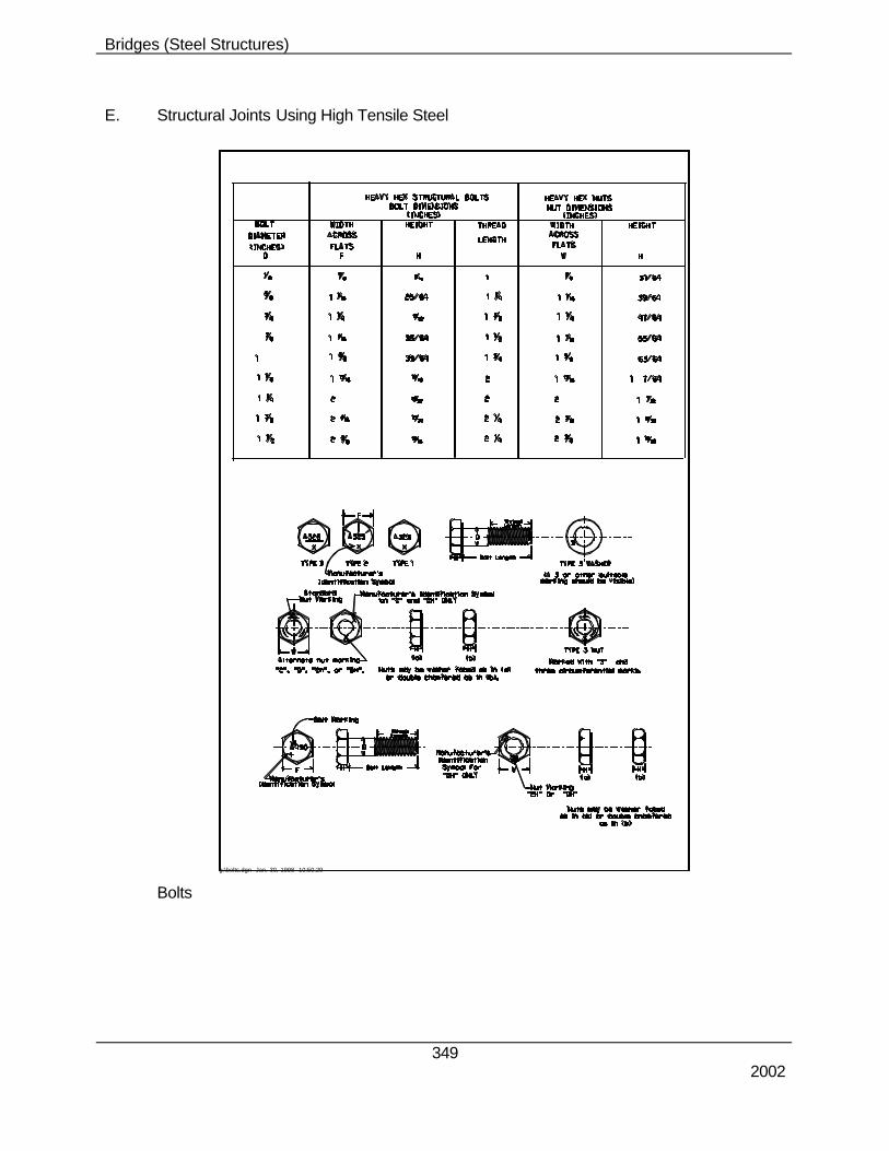
E. Structural Joints Using High Tensile Steel
Bolts
g:\bolts.dgn Jan. 30, 1998 10:50:29
Bridges (Steel Structures)
350 2002
g:\bolts.dgn Jan. 30, 1998 10:53:40
Bridges (Steel Structures)
351 2002
1. SSHC Section 1058 requires high tensile steel bolt, nut and washer material for structural steel joints to meet the requirements of ASTM Designation A 325/A 325M.
2. When heavy hexhead structural bolts and heavy hexagon nuts are used, a hardened
washer is required only under the bolt head, or nut, whichever is the element being turned. Bolts and nuts may be washer faced, but these faces do not take the place of a hardened washer.
3. Heavy hexhead structural bolts manufactured to ASTM A 325/A 325M, Types 1, 2 and
3, the dimensions for which are shown in the ASTM tables, are identified on the top of the head by the legend "A 325", and the manufacturer's symbol.
4. Type 1 bolts, at the option of the manufacturer, may be marked with three radial lines
120 degrees apart. 5. Type 2 bolts shall be marked with three radial lines 60 degrees apart. Type3 bolts
shall have the "A 325" underlined and the manufacturer may add other distinguishing marks indicating that the bolt is of a weathering type.
6. Heavy hex nuts for A 325 bolts are identified or at least one face by the
manufacturer's mark and the number "2" or "2H", by three equally spaced circumferential lines, or by the legend "D" or "DH". Heavy hex nuts for A 325 Type 3 bolts shall be marked on one face with three circumferential marks and the numeral "3", in addition to any other distinguishing marks the manufacturer may elect to use.
7. Washers for A 325 Type 3 bolts shall be marked on one face near the outer edge with
the numeral "3", or other distinguishing marks indicating that the washer is of a weathering type.
8. The marking on bearing surfaces of nuts and washers shall be depressed. 9. According to the specifications, high strength steel bolts may be installed by the turn
of the nut method. It should be noted that the equivalent torque values given in SSHC Table 708.03 are experimental approximations and that the footnote to this table required that the torque-tension ratio be determined under actual conditions of the application. Wrenches will be calibrated and the torque-tension ratio will be determined at the site by Materials and Research Division personnel. The Construction Engineer should be notified as early as possible as to the time when the wrench and representative bolts will be present at the site in order that arrangements may be made to have appropriate personnel travel to the site and calibrate the wrench and establish the torque-tension ratio.
10. When Materials and Research Division personnel have calibrated the wrench and
determined the torque-tension ratio, the bolt tension calibrator will be left with the project personnel so that the wrench calibration may be checked as the work goes on. Impact wrenches should be checked on a daily basis and manual torque wrenches at any time that, in the opinion of the Project Manager, conditions have varied form those present during the initial calibration.
11. Impact wrenches should be calibrated under the same conditions, such as length of
hose and power supply, that were present during actual installation of the bolts.
Bridges (Steel Structures)
352 2002
12. SSHC Subsection 708.03 requires that the structure shall be adjusted to the
requirements of blocking diagram before placing permanent bolts in field connections. This should be checked by the contractor and verified by the inspector prior to completing final phase of bolt tightening.
13. All splice plates and contact surfaces shall be clean.
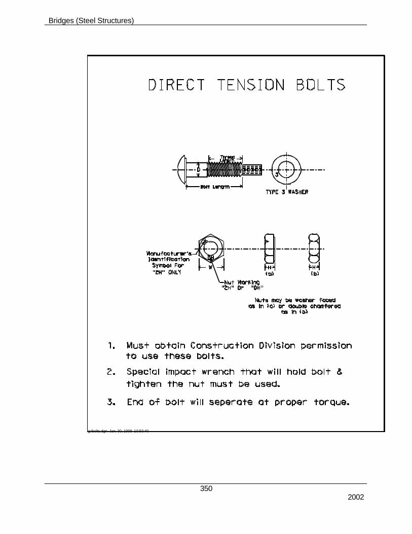
F. High Strength Fasteners (SSHC Section 1058)
METRIC HEAVY HEX BOLTS
g:\bolts.dgn Feb. 04, 1998 09:32:09
D Ds S E H Da R B (Ref.)
Thread Length (Basic)
Nominal Bolt Size & Thread Pitch
Body Diameter
Width Across
Flats
Width Across Corners
Head Height
Fillet Transition Dia.
Radius of Fillet
Bolt Lengths <125
Bolt Lengths
>125 and <200
Bolt Lengths
>200
Max. Min. Max. Min. Max. Min. Max. Min. Max. Min. M12x1.75
1. SSHC Subsection 708.03, Paragraph 10.h. Turn-of-Nut method shall be followed for
tightening all high strength fasteners. 2. High Strength bolts and nuts, which have been torqued as outlined below, shall not be
reused. This includes both black and galvanized bolts and nuts.
a. Bolting
(1) Receiving Shipments
(a) Prior to installation, check shipping certifications and compare these to bolting kegs on site. Check for size, length, heat numbers, and general fastener condition i.e., rusted black bolts or non-lubricated galvanized nuts. Rotational-Capacity (RC) lots will need to checked.
b. Installation Checklist
(1) A pre-bolting meeting is strongly recommended/encouraged. Bolting
procedures, Turn-of-Nut process described below, and the inspection process need to be discussed.
(2) Site storage of fasteners is important. Storage should be in a sealed
container within a sheltered storage shed. (3) Black bolts and nuts shall be oily to the touch when delivered and
installed. (4) Galvanized nuts shall be checked to verify lubrication. A uniform dye
color indicates lubricant has not been damaged. If there is no color, or color is not uniform, bolts and nuts shall be field lubricated with bees wax, stick wax, or other approved dry wax prior to installation.
(5) Rusted or dirty bolts or nuts shall be cleaned and relubricated prior to
installation. (6) Faying surfaces shall be free of burrs and foreign material; and bolted
faying surfaces are to be painted with zinc rich paint.
(7) All fasteners shall be free of dirt, moisture, rust, and be "well" lubricated.
(8) Washers (when required) are to be placed under the "turned
element." (9) Often contract documents will specify which way a bolt is to be
installed. If there is no specific guidance, threaded ends of bolts will be turned inside and away from normal exposure to pedestrian and/or vehicular traffic for aesthetic reasons.
Bridges (Steel Structures)
354 2002
(10) During installation, particular care should be exercised so a snug-tight condition is achieved.
c. Rotational-Capacity
(1) The plans and specifications may eventually require a Rotational-Capacity (RC) test for all "high strength" fasteners. This test confirms component compatibility and the presence of adequate lubrication. Currently, it is only required when the Project Manager determines it is necessary.
(2) There are two separate Rotational-Capacity requirements:
(a). Fasteners (bolts, nuts, and washers) received at the project shall have been RC tested by the supplier or manufacturer prior to shipment. Therefore, each combination of production lots must have an unique RC lot number. This number must be readily identifiable on each container of fasteners.
(b). Prior to installation, the contractor shall field test all RC lots as supplied. Field tests are not intended to match the values provided by the supplier, but as a separate and added acceptance test.
(c) Field testing procedures are given in SSHC Subsection 708.03, paragraph 10.h.
d. Turn-of-Nut Method
(1) "Turn-of-Nut" method involves the following simple steps. Adherence to this procedure will assure a properly fitted and clamped connection. (Refer to SSHC Subsection 708.03.)
(a) Adequate number of bolts and pins shall be installed to bring a
joint in tight contact and alignment. These bolts shall be brought to a snug-tight condition to insure that the joint is maintained in good contact during installation of remaining bolts. A washer shall be placed under the element to be turned.
(b) Remaining bolts in a connection shall be installed and brought
to a snug-tight condition. (c) Check initially installed bolts to assure they remained in a
snug-tight condition. (d) Tighten all bolts by the applicable Turn-of-Nut amount specified
in SSHC Subsection 708.03. Additional rotation depends on the bolt length to diameter ratio and shape of connected pieces. For MOST installations (both faces normal to bolt Axis) the following table can be used to determine additional rotation for Turn-of-Nut.
Bridges (Steel Structures)
355 2002
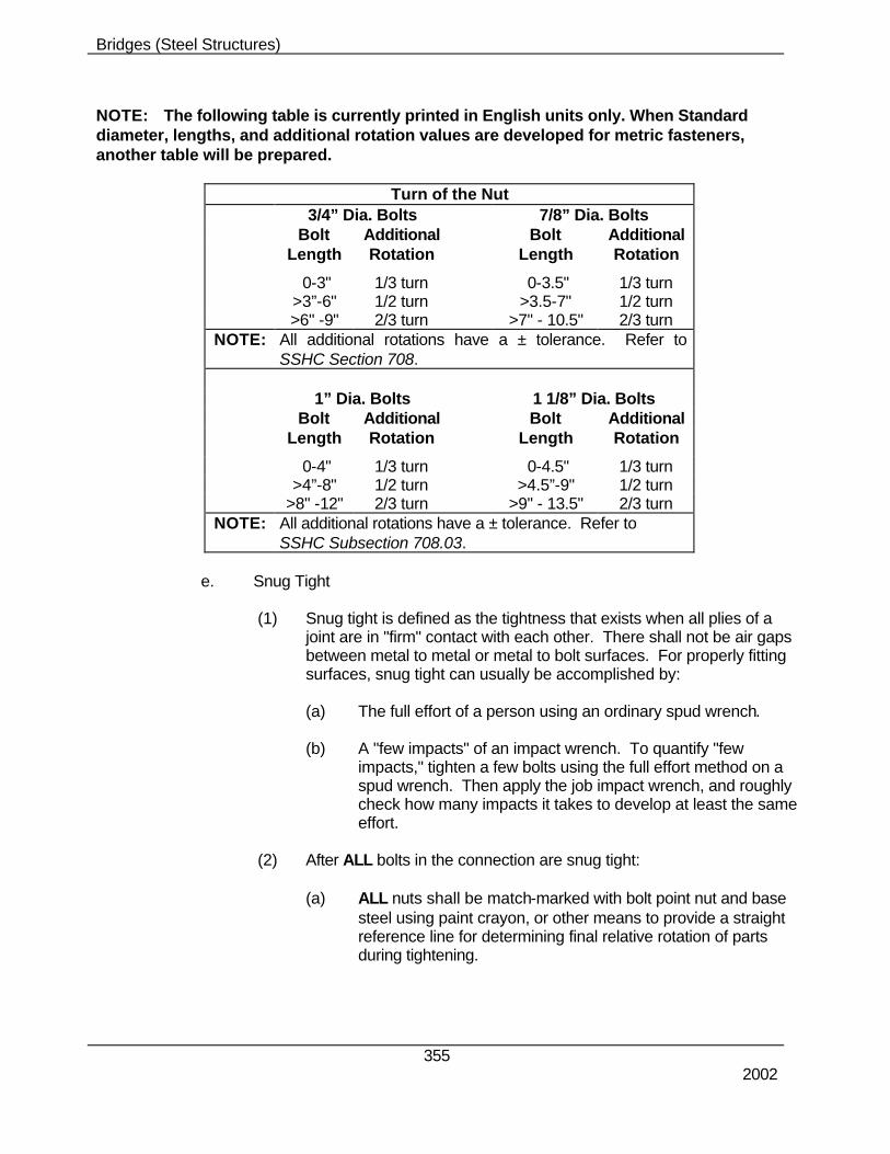
NOTE: The following table is currently printed in English units only. When Standard diameter, lengths, and additional rotation values are developed for metric fasteners, another table will be prepared.
Turn of the Nut 3/4” Dia. Bolts 7/8” Dia. Bolts Bolt Additional Bolt Additional Length Rotation Length Rotation
0-3" 1/3 turn 0-3.5" 1/3 turn >3”-6" 1/2 turn >3.5-7" 1/2 turn >6" -9" 2/3 turn >7" - 10.5" 2/3 turn NOTE: All additional rotations have a ± tolerance. Refer to SSHC Section 708.
0-4" 1/3 turn 0-4.5" 1/3 turn >4”-8" 1/2 turn >4.5”-9" 1/2 turn >8" -12" 2/3 turn >9" - 13.5" 2/3 turn NOTE: All additional rotations have a ± tolerance. Refer to SSHC Subsection 708.03.
e. Snug Tight
(1) Snug tight is defined as the tightness that exists when all plies of a
joint are in "firm" contact with each other. There shall not be air gaps between metal to metal or metal to bolt surfaces. For properly fitting surfaces, snug tight can usually be accomplished by:
(a) The full effort of a person using an ordinary spud wrench. (b) A "few impacts" of an impact wrench. To quantify "few
impacts," tighten a few bolts using the full effort method on a spud wrench. Then apply the job impact wrench, and roughly check how many impacts it takes to develop at least the same effort.
(2) After ALL bolts in the connection are snug tight:
(a) ALL nuts shall be match-marked with bolt point nut and base
steel using paint crayon, or other means to provide a straight reference line for determining final relative rotation of parts during tightening.
Bridges (Steel Structures)
356 2002
(b) All bolts in a connection shall then be tightened additionally by an applicable amount of nut rotation specified above. Tightening should progress from the most rigid part of the joint to its free edges. On our normal web and flange splices, this would mean beginning at the centerline of a splice and progressing away (in each direction) from the centerline of splice.
(3) Inspectors should observe this operation at intervals to make certain
the match-marking is done correctly, and that the opposite bolt head or nut does not turn during the tightening process. Inspectors also should check to see if proper rotation has been made considering tolerances given at the bottom of the nut rotation chart.
Wilhelm Calibrator) are calibrated to a high degree of accuracy, but can lose some of this accuracy after an extended period of time. Contractors can have the devices calibrated by the Materials & Research Laboratory.
(b) When each device is calibrated, a calibration sheet will be
issued indicating the date the test was performed. Contractors must keep the calibration sheet with the tension-measuring device.
(c) Attentiveness needs to be exercised when using this
Calibration Sheet. The inspector needs to check the sheet and compare the "Indicated Load on Gauge" column to those values listed in the "AVG" column under "Actual Load on Testing Machine." These are usually NOT the same.
NOTE: Be sure to take any difference (INDICATED versus ACTUAL) into account when calibrating the Job Torque Wrench!
(2) Torque Wrench Calibration
(a) At least once a day, three bolts of the same grade, size, and
condition as those used in the structure shall be placed individually in a calibration device capable of indicating bolt tension. A washer shall be used under the part to be turned.
NOTE: There must be 3-5 threads exposed behind the nut. Check and add washers if required. For longer bolts, steel shim plates should be used.
Bridges (Steel Structures)
357 2002
(i) Tension bolt to 100 percent of "Minimum Bolt Tension" listed for a particular bolt diameter. Tension is read directly from the tension measuring calibrated device as corrected by accounting for differences between INDICATED versus ACTUAL. (Refer to SSHC Subsection 708.03 for "Minimum Bolt Tension.")
(ii) Apply inspection torque wrench, rotate nut or bolt and increase tension by an additional 5%. Remember, a dial type wrench must be set to zero before checking torque. Record the inspection wrench's "TORQUE" when 105% of the tension is achieved.
NOTE: The turned element must be moving to indicate the correct torque.
should read: 39,250 + (40,000-38,800) = 40,450 lbs-force • For 105% tension, corrected Skidmore gauge
should read: 40,450 x 1.05 = 42,473 lbs-force (vi) torque reading on Inspection Wrench at 42,47O± lbs-
force is recorded.
(a) Repeat this process for a total of three fasteners. (b) The inspector notes the torque for three fasteners, averages
this torque, and that becomes the Job Inspection Torque Value until the wrench is recalibrated the next day, or another size or length of bolt is to be inspected.
Bridges (Steel Structures)
358 2002
The Inspector shall record: • The job inspection torque. • The Tension Measuring device's calibration "date reported,"
serial and model number, and calibration lab number.
g. Turn-of-Nut Inspection (SSHC Subsection 708.03)
(1) After all fasteners in a joint are properly tightened by the Turn-of-Nut method, they shall be inspected as indicated:
(a) Installed fasteners shall be inspected the same day as installed
by the contractor with the inspector present.
(b) The contractor shall use a calibrated torque wrench for the inspection operation.
(c) Ten percent of the bolts which have been tightened in the
structure shall be tested with the inspection wrench the same day as installed. At least two bolts, selected at random, in each connection shall be tested. If no rotation (nut or bolt head) is noted by job inspecting torque wrench and the faying surfaces are in tight contact the connection shall be accepted as properly tightened. If any nut or bolt head is turned, all bolts in the connection shall be checked, and all bolts whose nut or head is turned shall be tightened and reinspected.
(d) Bolts tightened by the Turn-of-Nut method may reach tensions
substantially above minimum torque values specified, but this shall not be cause for rejection.
(e) Care should be taken, however, to not overstress the bolts. If
most of the bolts exceed 20% of minimum bolt tension, the contractor's procedures should be reviewed to determine:
(i) Is the snug-tight procedure correct? (ii) Are there nicks or burrs on the threads? (iii) Are the nuts or bolts rusty or dirty? (iv) Check for residual lubrication. All threaded fasteners
(black and galvanized) are required to be lubricated. Black bolts and nuts need to have a water soluble oil, and galvanized nuts are to be lubricated as per ASTM A 563. Prelubricated galvanized nuts will be dyed typically to a blue color. If there is no indication of color OR if the color is faded, the bolts shall be field lubricated with bees wax, stick wax, or some other dry lubricant.
Bridges (Steel Structures)
359 2002
(v) Is calibrating device correct?
(4) Bolts and nuts must always be inspected prior to installation. Items of major concern are:
(a) Nicks or burrs in the threads (b) Rust
(c) Presence of dirt or other foreign material
(d) Fastener lubrication
(e) All dirt, foreign material, and rust must be removed prior to use. Black bolts may require reoiling to remove rust etc. If reoiling is required, excess oil must be removed prior to installation. When rust cannot be removed by oiling, the bolt or nut must be rejected. Bolts or nuts with nicks or burrs on threads must be rejected. Relubrication will necessitate rechecking fasteners in the lot for Rotational-Capacity.
(5) Plan ahead before girder splices have been fully tightened. Make necessary adjustments prior to tightening the bolts in a connection. The best way to assure that beam lines are straight and true is to:
(a) Scribe a line at the center of each bearing on all masonry plates or concrete.
(b) Set beams and make snug tight connections proceeding to the
forward pier. Then go back and straighten the beam line, checking to be sure bearings remain centered on their seats. Once the previous span is aligned and tightened, proceed to the next forward span.
(c) Check to be sure beam ends are aligned prior to tightening the
splice. (d) This will require coordination between survey and inspection
crews and the contractor.
h. Galvanized Bolts
(1) When using galvanized hardware, a lubricant approved by ASTM A 563 shall be applied to the nuts. Galvanized nuts "typically" are delivered to the project pre-lubricated. Usually, pre-lubricated nuts are stained and have a distinguishing color. If a lubricant has been applied at the fabrication shop, a field reapplication is not necessary provided original lubrication has not been removed in some manner. For situations where fabrication shop lubricant is in question, field application of bees wax, stick wax, or some other dry lubrication shall be required. Rotational-Capacity requires the test to be conducted with fasteners in the same condition as they will be during installation.
Bridges (Steel Structures)
360 2002
(2) A WORD OF CAUTION:
(a) Lubrication is required to minimize galling during installation.
Since nuts are lubricated (both threads and faces), it is important that nuts be rotated during tightening.
(b) Fasteners (bolts and nuts of any type) shall not be tightened,
then removed, reinstalled, and retightened. G. Welding (SSHC Subsection 708.03)
1. Contractors may be allowed to tack weld form hardware to the shear connectors on
steel girders. (The intent is to eliminate the request procedure.) 2. This policy does not apply to the rebar stirrups which extend out of the top of
prestressed girders. H. Shear Connectors
1. OSHA has made a determination that shear connectors on steel girders are a tripping
hazard. However, OSHA, after receiving petitions from FHWA, AASHTO, and other organizations, issued relief from the field welding requirements. The Department and other transportation agencies were concerned that field welded shear connectors created a bridge that would not be as safe as a bridge with shop welded shear connectors.
2. Girders may arrive on-site with all the shear connectors shop welded and this will not
be a citable violation of the OSHA shear connector requirements. It will be considered a “de minimis” violation, or in other words, a minor concern that has a very low probability of occurrence and where expenditure of resources is not warranted to ensure compliance.
3. 100 percent conventional fall protection is required for all workers working overhead
(6 feet or higher). 4. Shear connectors may either be shop welded or field welded.
• If they are field welded then the inspector needs to realize that welding shear connectors is a critical operation. The bridge may fail if the shear connectors are not welded properly.
• Use a “big” hammer to check field welded shear connectors.
Bridges (Steel Structures)
361 2002
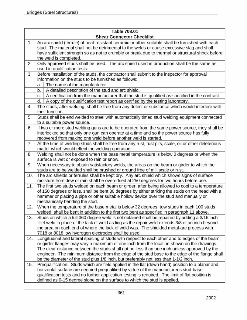
Table 708.01 Shear Connector Checklist
1. An arc shield (ferrule) of heat-resistant ceramic or other suitable shall be furnished with each stud. The material shall not be detrimental to the welds or cause excessive slag and shall have sufficient strength so as not to crumble or break due to thermal or structural shock before the weld is completed.
2. Only approved studs shall be used. The arc shield used in production shall be the same as used in qualification tests.
3. Before installation of the studs, the contractor shall submit to the inspector for approval information on the studs to be furnished as follows:
a. The name of the manufacturer. b. A detailed description of the stud and arc shield. c. A certification from the manufacturer that the stud is qualified as specified in the contract. d. A copy of the qualification test report as certified by the testing laboratory. 4. The studs, after welding, shall be free from any defect or substance which would interfere with
their function. 5. Studs shall be end welded to steel with automatically timed stud welding equipment connected
to a suitable power source. 6. If two or more stud welding guns are to be operated from the same power source, they shall be
interlocked so that only one gun can operate at a time and so the power source has fully recovered from making one weld before another weld is started.
7. At the time of welding studs shall be free from any rust, rust pits, scale, oil or other deleterious matter which would effect the welding operation.
8. Welding shall not be done when the base metal temperature is below 0 degrees or when the surface is wet or exposed to rain or snow.
9. When necessary to obtain satisfactory welds, the areas on the beam or girder to which the studs are to be welded shall be brushed or ground free of mill scale or rust.
10. The arc shields or ferrules shall be kept dry. Any arc shield which shows signs of surface moisture from dew or rain shall be oven-dried at 250 degrees for two hours before use.
11. The first two studs welded on each beam or girder, after being allowed to cool to a temperature of 150 degrees or less, shall be bent 30 degrees by either striking the studs on the head with a hammer or placing a pipe or other suitable hollow device over the stud and manually or mechanically bending the stud.
12. When the temperature of the base metal is below 32 degrees, tow studs in each 100 studs welded, shall be bent in addition to the first two bent as specified in paragraph 11 above.
13. Studs on which a full 360 degree weld is not obtained shall be repaired by adding a 3/16 inch fillet weld in place of the lack of weld as ling as the repair weld extends 3/8 of an inch beyond the area on each end of where the lack of weld was. The shielded metal-arc process with 7018 or 8018 low hydrogen electrodes shall be used.
14. Longitudinal and lateral spacing of studs with respect to each other and to edges of the beam or girder flanges may vary a maximum of one inch from the location shown on the drawings. The clear distance between the studs shall not be less than one inch unless approved by the engineer. The minimum distance from the edge of the stud base to the edge of the flange shall be the diameter of the stud plus 1/8 inch, but preferably not less than 1-1/2 inch.
15. Prequalification. Studs which are field applied in the flat (down hand) position to a planar and horizontal surface are deemed prequalified by virtue of the manufacturer’s stud-base qualification tests and no further application testing is required. The limit of flat position is defined as 0-15 degree slope on the surface to which the stud is applied.
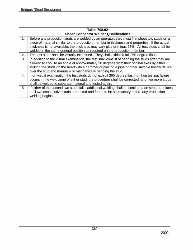
1. Before any production studs are welded by an operator, they must first shoot tow studs on a piece of material similar to the production member in thickness and properties. If the actual thickness is not available, the thickness may vary plus or minus 25%. All test studs shall be welded in the same general position as required on the production member.
2. The test studs shall be visually examined. They shall exhibit a full 360-degree flash. 3. In addition to the visual examination, the test shall consist of bending the studs after they are
allowed to cool, to an angle of approximately 30 degrees from their original axes by either striking the studs on the head with a hammer or placing a pipe or other suitable hollow device over the stud and manually or mechanically bending the stud.
4. If on visual examination the test studs do not exhibit 360 degree flash, or if on testing, failure occurs in the weld zone of either stud, the procedure shall be corrected, and two more studs shall be welded to separate material and tested again.
5. If either of the second two studs fails, additional welding shall be continued on separate plates until two consecutive studs are tested and found to be satisfactory before any production welding begins.
Bridges (Steel Structures)
363 2002
g:\weld1.dgn Jan. 30, 1998 10:11:15
Bridges (Steel Structures)
364 2002
g:\weld1.dgn Jan. 30, 1998 10:19:58
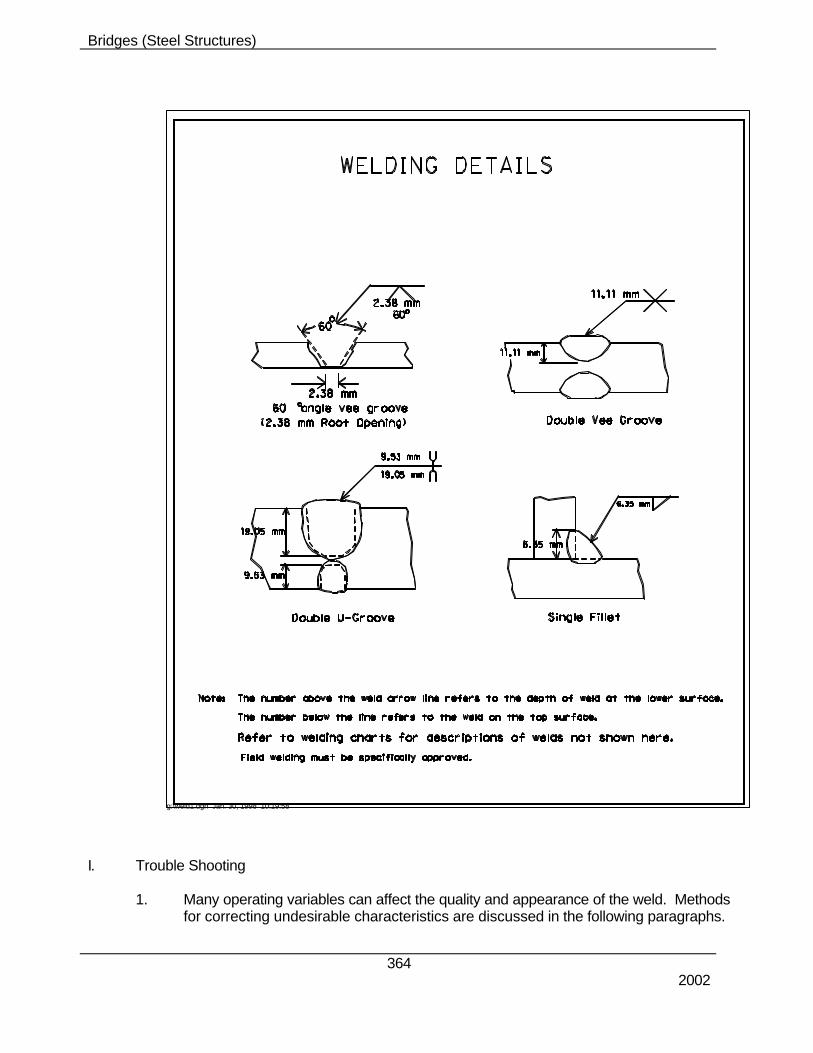
I. Trouble Shooting
1. Many operating variables can affect the quality and appearance of the weld. Methods
for correcting undesirable characteristics are discussed in the following paragraphs.
Bridges (Steel Structures)
365 2002
J. Weld Spatter 1. Spatter does not affect weld strength but does produce a poor appearance and
increases cleaning costs.
(a) Be sure to control excessive splatter. Try lowering the current. Be sure the current is within the recommended range for the and size electrode (see attached Table).
(b) Be sure the polarity is correct for the electrode type.
(c) Try a shorter arc length.
(d) If the molten metal is running in front of the arc, change the electrode angle.
(e) Watch for arc blow.
(f) The electrode is not too wet.
K. Undercut
1. Generally, the only harm from undercutting is impaired appearance. However, undercutting may also impair weld strength, particularly when the weld is loaded in tension or subjected to fatigue. To minimize undercut:
(a) Reduce current, travel speed, or electrode size until the puddle is
manageable. (b) Change electrode angle so the arc force holds the metal in the corners. Use
a uniform travel speed and avoid excessive weaving. L. Rough Welding
1. If polarity and current are within the electrode manufacturer's recommendations but
the arc action is rough and erratic, the electrodes may be wet. Try electrodes from a fresh container. If the problem occurs frequently, store open containers of electrodes in a heated cabinet.
M. Porosity and Surface Holes
1. Most porosity is not visible. But severe porosity can weaken the weld. The following
practices minimize porosity:
(a) Remove scale, rust, paint, moisture, or dirt from the joint. Generally use an E6010 or E6011 electrode for dirty steel.
(b) Keep the puddle molten for a long time, so that gases may boil out before the
metal freezes.
Bridges (Steel Structures)
366 2002
(c) Steels very low in carbon or manganese or those high in sulfur or phosphorus should be welded with a low-hydrogen electrode. Minimize admixture of base metal with weld metal by using low currents and fast travel speeds for less penetration.
(d) Try using a short arc length; short arcs are required for low-hydrogen
electrodes.
2. Surface holes can be avoided by many of the practices used to minimize porosity.
N. Poor Fusion 1. Proper fusion exists when the weld bonds to both walls of the joint and forms a solid
bead across the joint. Lack of fusion is often visible and must be avoided for a sound weld. To correct poor fusion:
(a) Try a higher current and a stringer-bead technique. (b) Be sure the edges of the joint are clean, or use an E6010 or E6011 electrode. (c) If gap is excessive, provide better fitup or use a weave technique to fill the
gap. O. Shallow Penetration
1. Penetration refers to the depth the weld enters into the base metal. For full-strength
welds, penetration to the bottom of the joint is required. To overcome shallow penetration:
(a) Try higher currents or slower travel. (b) Use small electrodes to reach into deep, narrow grooves. (c) Allow some gap (free space) at the bottom of the joint.
P. Cracking
1. Many different types of cracks may occur throughout a weld. Some are visible and
some are not. However, all cracks are potentially serious, because they can lead to complete failure of the weld. The following suggestions may help control potential cracking.
2. Most cracking is attributed to high-carbon or alloy content or high-sulfur content in the
base metal. To control this type of cracking:
(a) Use low-hydrogen electrodes. (b) Preheat. Use high preheat for heavier plate and rigid joints. (c) Reduce penetration by using low currents and small electrodes. This
reduces the amount of alloy added to the weld from melted base metal.
Bridges (Steel Structures)
367 2002
(d) To control crater cracking, fill each crater before breaking the arc. Use a
back-stepping technique so as to end each weld on the crater of the previous weld.
3. On multiple-pass or fillet welds, be sure the first bead is of sufficient size and of flat or
convex shape to resist cracking until the later beads can be added for support. To increase bead size, use slower travel speed, a short arc, or weld 5° uphill. Always continue welding while the plate is hot.
4. Rigid parts are more prone to cracking. If possible, weld toward the unrestrained
ends. Leave a 1/32 inch (0.8 mm) gap between plates for free shrinkage movement as the weld cools. Peen each bead while is still hot to relieve stresses.
Q. How to Reduce Arc Blow
1. All arc blow is not detrimental. In fact, a small amount of arc blow can sometimes be used beneficially to help form the bead shape, control molten slag, and control penetration.
2. When arc blow is causing or contributing to such defects as undercut, inconsistent
penetration, crooked beads, beads of irregular width, porosity, wavy beads, and excessive spatter, it must be controlled. Possible corrective measures have already been suggested in the preceding text. In general, here are some methods that might be considered:
a. If DC current is being used with the shielded metal-arc process - especially at
rates above 250 amperes - a change to AC current may eliminate problems. b. Hold as short an arc as possible to help the arc force counteract the arc blow. c. Reduce the welding current - which may require a reduction in arc speed. d. Angle the electrode with the work opposite the direction of arc blow. e. Make a heavy tack weld on both ends of the seam; apply frequent tack welds
along the seam, especially if the fitup is not tight. f. Weld toward a heavy tack or toward a weld already made. g. Use a back-step welding technique. h. Weld away from the ground to reduce back blow; weld toward the ground to
reduce forward blow. i. With processes where a heavy slag is involved, a small amount of back blow
may be desirable; to get this, weld toward the ground. j. Wrap ground cable around the work piece and pass ground current through it
in such a direction that the magnetic field set up will tend to neutralize the magnetic field causing the arc blow.
Bridges (Steel Structures)
368 2002
3. The direction of the arc blow can be observed with an open-arc process, but with the
submerged arc process must be determined by the type of weld defect. 4. Back blow is indicated by the following:
a. Spatter. b. Undercut, either continuous or intermittent. c. Narrow, high bead, usually with undercut. d. An increase in penetration. e. Surface porosity at the finish end of weld on sheet metal.
5. Forward blow is indicated by:
a. A wide bead, irregular in width. b. Wavy bead. c. Undercut, usually intermittent. d. A decrease in penetration.
R. The Effects of Fixturing on Arc Blow
1. Steel fixtures for holding the work pieces may have an effect on the magnetic field
around the arc and, thus, on arc blow. Usually, the fixturing causes no problem with stick-electrode welding when the current does not exceed 250 amperes. Fixtures for use with higher currents and with mechanized welding should be designed with precautions taken so that an arc-blow-promoting situation is not built into the fixture.
2. Each fixturing device may require special study to ascertain the best way to prevent
the fixture from interfering deleteriously with the magnetic fields. The following are some points to note:
a. Fabricate the fixture from low-carbon steel. This is to prevent the buildup of
permanent magnetism in the fixture. b. Welding toward the closed end of "horn type" fixtures reduces back blow. c. Design the fixture long enough so that end tabs can be used if necessary. d. Do not use a copper strip inserted in a steel bar for a backing. The steel part
of the backup bar will increase arc blow. e. Provide for continuous or close clamping of parts to be seam-welded. Wide,
intermittent clamping may cause seams to gap between clamping points, resulting in arc blow over the gaps.
Bridges (Steel Structures)
369 2002
f. Do not build into the fixture large masses of steel on one side of the seam
only. Counterbalance with a similar mass on the other side.
704.04 METHOD OF MEASUREMENT A. Structural steel is usually measured by the pound (kg). Structural steel for handrail is also
measured by the pound. Ornamental handrails are measured by the lineal feet of rail between end posts. These values are listed on the plans and may be used in the final computation for payment.
704.05 BASIS OF PAYMENT A. PMs are authorized to pay for steel plates and shapes as soon as the material arrives at the
fabricator. B. The Nebraska Department of Roads had determined that it may be possible to improve
inspection procedures and to lower construction costs on bridges and other structures where significant quantities of steel are required if stockpiled materials are paid for upon receipt by the fabricator. Therefore, the Department will allow partial payments for stockpiled steel plates and shapes prior to fabrication. The procedure that must be followed before partial payment will be made is as follows: 1. The prime contractor must request partial payment from the Department’s Project
Manager for the specific project where payment is requested. 2. The Bridge Divisions, Fabrication Inspector [(402)-479-4763] will be responsible for
verifying fabricators’ invoices and forwarding them to the project managers; for verifying manufacturer’s Certified Mill Test Report and forwarding copies to the PM and M&R Division; and for inspection of the steel.
3. The fabricator must provide the Department’s Fabrication Inspector the steel
manufacturer’s paid invoice for the material. The Project Manager will make the payment for the amount shown on the invoice, which directly is attributed to the project for which payment is being considered. The invoice should be annotated to show:
(a) the project number (b) steel quantity in pounds applicable to the project (c) material grade (d) material heat number
4. There must be identifying marks placed on each piece for which payment will be
made.
Bridges (Steel Structures)
370 2002
5. Steel must be stored in orderly fashion to readily facilitate identification of specific materials to specific projects. Project materials cannot be commingled with other projects – each project’s materials must have a separate location.
6. The Manufacturer’s Certified Mill Test Reports must be provided to and approved by
the Bridge Division before payment will be authorized. The Bridge Division will notify the Project Manager when payment is authorized.
7. The Department will verify that the material is properly stored before payment will be
made. 8. The Prime Contractor will make payment to the fabricator within 20 days after the
Department has paid for the material. 9. Payment is only authorized for materials that are stored within Nebraska as specified
in Subsection 109.07 of the Nebraska Standard Specifications for Highway Construction.