7.125 Simulation Of Mono And Dual-Wavelength Airborne Radar Observations Of Precipitating Systems At Various Frequency Bands V. Louf 1* , O. Pujol 1 , H. Sauvageot 2 , J. Riedi 1 , and G. Pénide 1 1 Université Lille 1, Laboratoire d’Optique Atmosphérique (LOA); 2 Université Toulouse III, Observatoire Midi-Pyrénées. 1. Introduction We address the question of the most efficient cou- ple (f , θ 3dB ) for airborne radar precipitating sys- tem observations, where f is the microwave fre- quency and θ 3dB the beamwidth aperture at 3 dB (θ 3dB = 70λ/D a , D a is antenna diameter) (Skolnik 2008). This problem is of importance. The mete- orological hazard in civil aviation is mainly due to convective precipitating systems, and particularly hail and strong turbulence areas. A realistic and flexible model of precipitating systems is presented and simulations of airborne radar observations are performed at the six mete- orological frequency bands. In this work, the effect of f and θ 3dB modification is shown through radar simulations of several precipitating systems. One is a numerical simulation composed of two succes- sive rows of convective towers, another is inspired from NEXRAD data of a real mesoscale event of May 2 nd , 2003 in Alabama (USA), presenting hail- bearing convective towers. It is shown that some (f , θ 3dB ) couples are better than the one currently used by civil aviation. Notably C-band allows a better description than X-band of a meteorological radar scene, if the radar antenna size is increased. After that, we applied the dual-wavelength method to detect unambiguously hail in these pre- cipitating systems. The question of the most efficient dual-wavelength couple is addressed by comparing several meteorological radar dual- bands. Since hail reflectivity is strongly dependent on microwave frequency (Atlas and Ludlam 1961), an interesting method to improve hail detection in airborne radar is the dual-wavelength technique (DWT). As a non-Rayleigh scatterer at S, C, and X- * Corresponding author address: Valentin Louf, Université Lille 1, Laboratoire d’Optique Atmosphérique, 59655 Villeneuve d’Ascq, France; e-mail: [email protected]bands, hail reflectivity field is considerably higher as the frequency decreases. It is shown that even if S-X is the best couple, because the reflectivity difference is the highest, C-X is a dual-wavelength of interest. It is also shown that, because of the non-Rayleigh scattering behavior of hailstones, the derivative of the dual-wavelength reflectivity ratio is a tool that can unambiguously detect hail on the radar signal path. 2. Method Simulation of precipitating system observations are made using the method described in detail in Louf et al. (2013). Briefly, it consists in model- ing a mesoscale precipitating system with several convective towers surrounded by a stratiform back- ground (Houze 1997). This system is composed of nine hydrometeor categories (rain, dry and wet hail, dry and wet snow, graupel, drizzle, ice crys- tals, and water droplets), each one being charac- terized by a three-dimensional concentration field and a size spectrum distribution. Observations are simulated for an airborne radar located on a plane flying at 10 km of altitude which operates at the six meteorological frequencies S (f ≈ 3 GHz, λ ≈ 10.7 cm), C (f ≈ 5.5 GHz, λ ≈ 5.5 cm), X (f ≈ 9.4 GHz, λ ≈ 3.2 cm), K u (f ≈ 15 GHz, λ ≈ 2 cm), K a (f ≈ 35 GHz, λ ≈ 0.86 cm), and W (f ≈ 94 GHz, λ ≈ 0.32 cm). Range bin spac- ing Δr is set to 150 m. Electromagnetic energy is supposed to be uniformly distributed The size distribution of each hydrometeor cate- gory is required to compute the reflectivity fields, and thus, a complete modeling of the target mi- crophysics is needed (Pruppacher and Klett 1997). The detail for all hydrometeor categories can be found in Louf et al. (2013). Equivalent radar re- 1
Transcript
7.125
Simulation Of Mono And Dual-Wavelength AirborneRadar Observations Of Precipitating Systems At
Various Frequency Bands
V. Louf1∗, O. Pujol1, H. Sauvageot2, J. Riedi1, and G. Pénide1
1Université Lille 1, Laboratoire d’Optique Atmosphérique (LOA);2Université Toulouse III, Observatoire Midi-Pyrénées.
1. Introduction
We address the question of the most efficient cou-ple (f , θ3dB) for airborne radar precipitating sys-tem observations, where f is the microwave fre-quency and θ3dB the beamwidth aperture at 3 dB(θ3dB = 70λ/Da, Da is antenna diameter) (Skolnik2008). This problem is of importance. The mete-orological hazard in civil aviation is mainly due toconvective precipitating systems, and particularlyhail and strong turbulence areas.
A realistic and flexible model of precipitatingsystems is presented and simulations of airborneradar observations are performed at the six mete-orological frequency bands. In this work, the effectof f and θ3dB modification is shown through radarsimulations of several precipitating systems. Oneis a numerical simulation composed of two succes-sive rows of convective towers, another is inspiredfrom NEXRAD data of a real mesoscale event ofMay 2nd, 2003 in Alabama (USA), presenting hail-bearing convective towers. It is shown that some(f , θ3dB) couples are better than the one currentlyused by civil aviation. Notably C-band allows abetter description than X-band of a meteorologicalradar scene, if the radar antenna size is increased.
After that, we applied the dual-wavelengthmethod to detect unambiguously hail in these pre-cipitating systems. The question of the mostefficient dual-wavelength couple is addressedby comparing several meteorological radar dual-bands. Since hail reflectivity is strongly dependenton microwave frequency (Atlas and Ludlam 1961),an interesting method to improve hail detection inairborne radar is the dual-wavelength technique(DWT). As a non-Rayleigh scatterer at S, C, and X-
bands, hail reflectivity field is considerably higheras the frequency decreases. It is shown that evenif S-X is the best couple, because the reflectivitydifference is the highest, C-X is a dual-wavelengthof interest. It is also shown that, because of thenon-Rayleigh scattering behavior of hailstones, thederivative of the dual-wavelength reflectivity ratiois a tool that can unambiguously detect hail on theradar signal path.
2. Method
Simulation of precipitating system observationsare made using the method described in detail inLouf et al. (2013). Briefly, it consists in model-ing a mesoscale precipitating system with severalconvective towers surrounded by a stratiform back-ground (Houze 1997). This system is composedof nine hydrometeor categories (rain, dry and wethail, dry and wet snow, graupel, drizzle, ice crys-tals, and water droplets), each one being charac-terized by a three-dimensional concentration fieldand a size spectrum distribution.
Observations are simulated for an airborne radarlocated on a plane flying at 10 km of altitude whichoperates at the six meteorological frequenciesS (f ≈ 3 GHz,λ ≈ 10.7 cm), C (f ≈ 5.5 GHz,λ ≈5.5 cm), X (f ≈ 9.4 GHz,λ ≈ 3.2 cm), Ku (f ≈15 GHz,λ ≈ 2 cm), Ka (f ≈ 35 GHz,λ ≈ 0.86 cm),and W (f ≈ 94 GHz,λ ≈ 0.32 cm). Range bin spac-ing ∆r is set to 150 m. Electromagnetic energy issupposed to be uniformly distributed
The size distribution of each hydrometeor cate-gory is required to compute the reflectivity fields,and thus, a complete modeling of the target mi-crophysics is needed (Pruppacher and Klett 1997).The detail for all hydrometeor categories can befound in Louf et al. (2013). Equivalent radar re-
1
flectivity factor and attenuation are then computedfrom backscattering (σ) and attenuation (Q) crosssections of spherical scatterers given by Mie for-mulas. For a given radar cell of volume V, theprocedure consists in identifying the grid points in-cluded in V and, for each of these grid points, tocompute σ and Q at the considered microwavefrequency. The equivalent radar reflectivity factorof V is finally calculated with the Probert-Jones(1962) equation. The simulation is fully completedwhen the successive radar beams separated by∆θ = 0.1◦ in azimuth have covered the whole ex-tent of the target.
Figure 1: (a) Numerical model configuration.Radar is located at (0, 0, 10), range markers arecircumscribing every 50 km. The cell center of thefirst row of convective tower is at 110 km from theradar and the second at 130 km. The towers havecircular horizontal section with diameter of 10 km.(b) Normalized vertical profile of hydrometeors ina convective tower. For the hydrometeor categoryα, Mα is the water content and Rα the precipitationrate.
3. Frequency and θ3dB-beam-width comparison
Figure 2 shows a PPI view of the simulated Zm-field at the six frequency bands of a plane fly-ing along azimuth direction 0◦, at 10 km of alti-tude. Zm-field degradation is clearly visible. At Sand C -bands (Fig. 2a, b), although the large θ3dBbeamwidths do not permit to isolate each convec-tive towers, two lines of convection of reflectivitygreater than 50 dBZ are clearly visible. At X−band(Fig. 2c), only the first row of convection is seenwith the correct range of reflectivity while the sec-ond row is attenuated. The farthest one does notseem to be dangerous: reflectivity falls down of15 dB because of attenuation. Attenuation is worsefor the highest frequency bands, i.e. at Ku (Fig.
2d), Ka (Fig. 2e), and W (Fig. 2f) bands, forwhich the convective system is clearly unobserv-able. These three bands are not appropriate forhail and/or high rainfall detection. They are not in-teresting for meteorological hazard estimation, al-though these microwaves propagate with a narrowbeam in spite of small radar antenna.
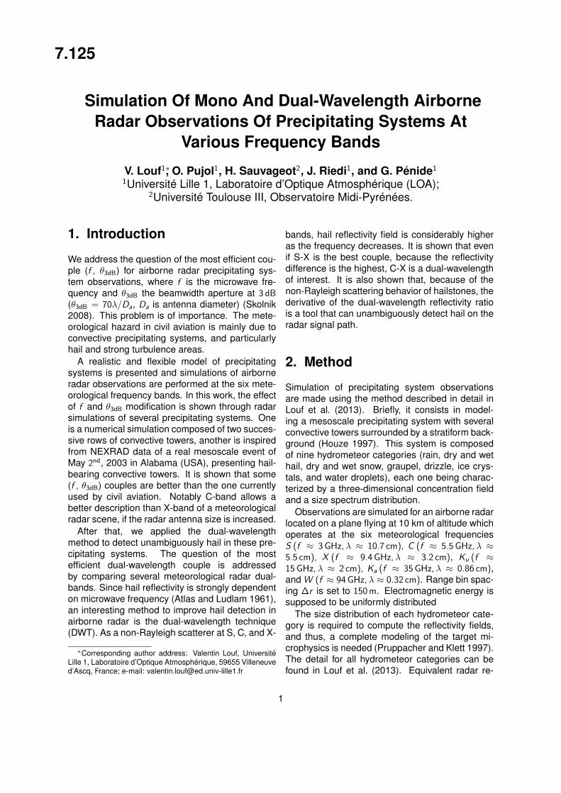
The same conclusion holds for an RHI view, likethat presented on Fig. 3 for an azimuth of 0◦,i.e. with a perfect alignment of the radar with thetwo centered convective cells. The cumulonimbusare easily identifiable at S , C , and X -bands (Fig.3a, b, and c respectively), despite the large θ3dB-beamwidths used. However, attenuation destroysthe possibility to observe unambiguously these twoconvective towers at Ku, Ka, and W -bands (Fig.3d, e, and f).
Figure 2: Simulation of a PPI view (altitude 10 km)of Zm( dBZ), at: S(a), C (b), X (c), Ku(d), Ka(e), andW (f). Radar antenna diameter is 200 cm (a, b) and80 cm (c, d, e, f). R indicates radar position. Rangemarkers are as in Fig. 1a.
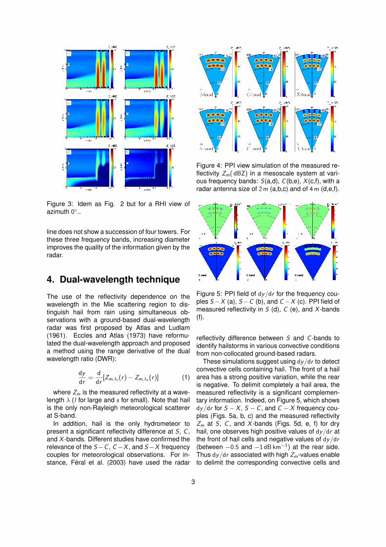
In order to study the angular resolution effect,several others simulations have been performed.Radar antenna diameter has been changed. OnFigure 4a, b, and c, radar antenna diameter is 2 mfor all three bands. The corresponding angular res-olutions are θ3 dB = 3.7◦ for S-band, 1.9◦ for C -band, and 1.1◦ for X -band. Compared to Figure 2,there is no substantial change for S and C -bands.However, X−band presents a good improvement(Fig. 4c), since the eight convective towers seemsto be quite well separated. In addition, they ap-pear to be less attenuated than in Figure 2, sincethe radar resolution volume has been decreased.
Fig. 4d, e, and f the radar antenna diameteris 4 m, which gives θ3dB-beamwidths of 1.9◦, 0.9◦,and 0.5◦ at S , C , and X -bands respectively. All theconvective towers are clearly identifiable at X andC−bands. At S−band, only the second convective
2
Figure 3: Idem as Fig. 2 but for a RHI view ofazimuth 0◦..
line does not show a succession of four towers. Forthese three frequency bands, increasing diameterimproves the quality of the information given by theradar.
4. Dual-wavelength technique
The use of the reflectivity dependence on thewavelength in the Mie scattering region to dis-tinguish hail from rain using simultaneous ob-servations with a ground-based dual-wavelengthradar was first proposed by Atlas and Ludlam(1961). Eccles and Atlas (1973) have reformu-lated the dual-wavelength approach and proposeda method using the range derivative of the dualwavelength ratio (DWR):
dy
dr=
d
dr[Zm,λl
(r)− Zm,λs (r)] (1)
where Zm is the measured reflectivity at a wave-length λ (l for large and s for small). Note that hailis the only non-Rayleigh meteorological scattererat S-band.
In addition, hail is the only hydrometeor topresent a significant reflectivity difference at S , C ,and X -bands. Different studies have confirmed therelevance of the S−C , C−X , and S−X frequencycouples for meteorological observations. For in-stance, Féral et al. (2003) have used the radar
Figure 4: PPI view simulation of the measured re-flectivity Zm( dBZ) in a mesoscale system at vari-ous frequency bands: S(a,d), C (b,e), X (c,f), with aradar antenna size of 2 m (a,b,c) and of 4 m (d,e,f).
Figure 5: PPI field of dy/dr for the frequency cou-ples S−X (a), S−C (b), and C−X (c). PPI field ofmeasured reflectivity in S (d), C (e), and X -bands(f).
reflectivity difference between S and C -bands toidentify hailstorms in various convective conditionsfrom non-collocated ground-based radars.
These simulations suggest using dy/dr to detectconvective cells containing hail. The front of a hailarea has a strong positive variation, while the rearis negative. To delimit completely a hail area, themeasured reflectivity is a significant complemen-tary information. Indeed, on Figure 5, which showsdy/dr for S − X , S − C , and C − X frequency cou-ples (Figs. 5a, b, c) and the measured reflectivityZm at S , C , and X -bands (Figs. 5d, e, f) for dryhail, one observes high positive values of dy/dr atthe front of hail cells and negative values of dy/dr(between −0.5 and −1 dB km−1) at the rear side.Thus dy/dr associated with high Zm-values enableto delimit the corresponding convective cells and
3
hail areas.In order to illustrate the usefulness of the dual-
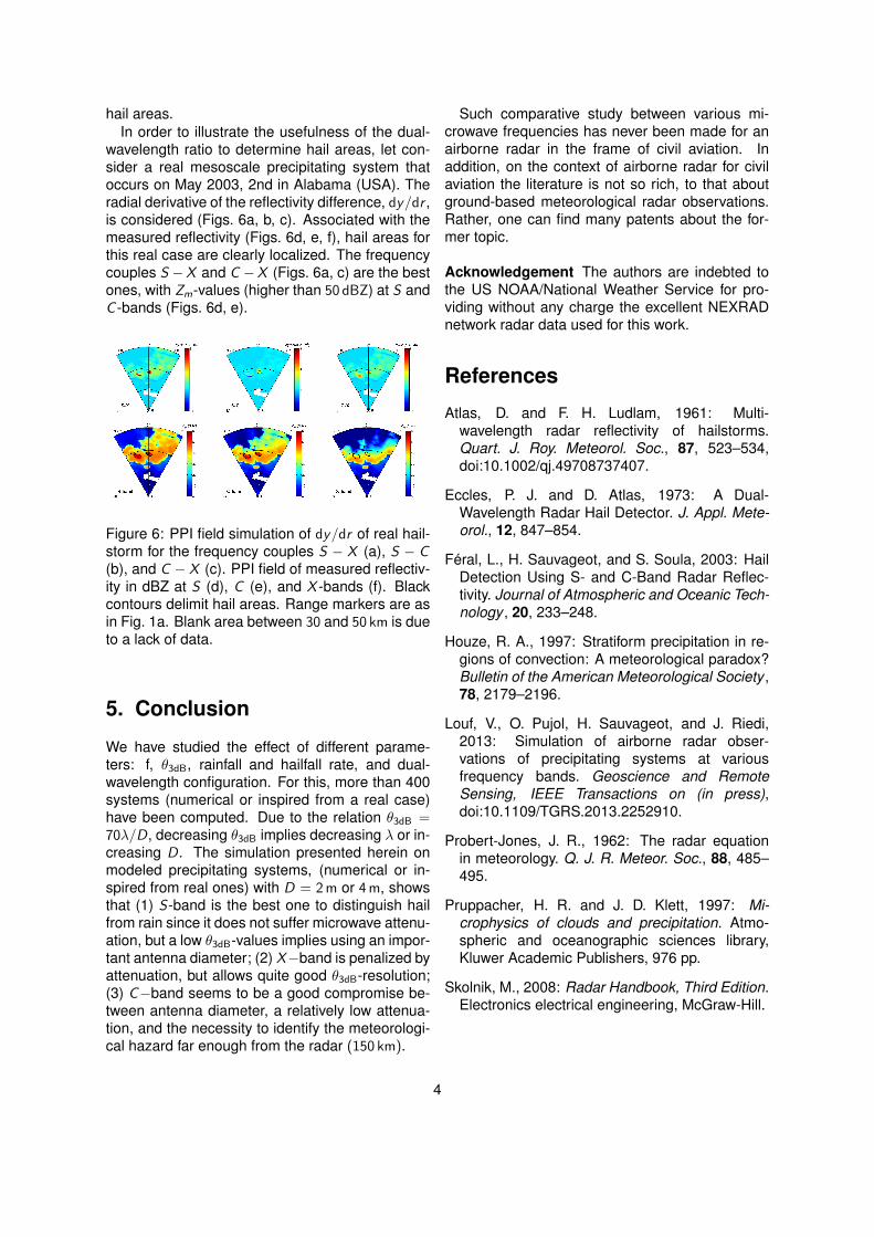
wavelength ratio to determine hail areas, let con-sider a real mesoscale precipitating system thatoccurs on May 2003, 2nd in Alabama (USA). Theradial derivative of the reflectivity difference, dy/dr ,is considered (Figs. 6a, b, c). Associated with themeasured reflectivity (Figs. 6d, e, f), hail areas forthis real case are clearly localized. The frequencycouples S −X and C −X (Figs. 6a, c) are the bestones, with Zm-values (higher than 50 dBZ) at S andC -bands (Figs. 6d, e).
Figure 6: PPI field simulation of dy/dr of real hail-storm for the frequency couples S − X (a), S − C(b), and C − X (c). PPI field of measured reflectiv-ity in dBZ at S (d), C (e), and X -bands (f). Blackcontours delimit hail areas. Range markers are asin Fig. 1a. Blank area between 30 and 50 km is dueto a lack of data.
5. Conclusion
We have studied the effect of different parame-ters: f, θ3dB, rainfall and hailfall rate, and dual-wavelength configuration. For this, more than 400systems (numerical or inspired from a real case)have been computed. Due to the relation θ3dB =70λ/D, decreasing θ3dB implies decreasing λ or in-creasing D. The simulation presented herein onmodeled precipitating systems, (numerical or in-spired from real ones) with D = 2 m or 4 m, showsthat (1) S-band is the best one to distinguish hailfrom rain since it does not suffer microwave attenu-ation, but a low θ3dB-values implies using an impor-tant antenna diameter; (2) X−band is penalized byattenuation, but allows quite good θ3dB-resolution;(3) C−band seems to be a good compromise be-tween antenna diameter, a relatively low attenua-tion, and the necessity to identify the meteorologi-cal hazard far enough from the radar (150 km).
Such comparative study between various mi-crowave frequencies has never been made for anairborne radar in the frame of civil aviation. Inaddition, on the context of airborne radar for civilaviation the literature is not so rich, to that aboutground-based meteorological radar observations.Rather, one can find many patents about the for-mer topic.
Acknowledgement The authors are indebted tothe US NOAA/National Weather Service for pro-viding without any charge the excellent NEXRADnetwork radar data used for this work.
References
Atlas, D. and F. H. Ludlam, 1961: Multi-wavelength radar reflectivity of hailstorms.Quart. J. Roy. Meteorol. Soc., 87, 523–534,doi:10.1002/qj.49708737407.
Eccles, P. J. and D. Atlas, 1973: A Dual-Wavelength Radar Hail Detector. J. Appl. Mete-orol., 12, 847–854.
Féral, L., H. Sauvageot, and S. Soula, 2003: HailDetection Using S- and C-Band Radar Reflec-tivity. Journal of Atmospheric and Oceanic Tech-nology , 20, 233–248.
Houze, R. A., 1997: Stratiform precipitation in re-gions of convection: A meteorological paradox?Bulletin of the American Meteorological Society ,78, 2179–2196.
Louf, V., O. Pujol, H. Sauvageot, and J. Riedi,2013: Simulation of airborne radar obser-vations of precipitating systems at variousfrequency bands. Geoscience and RemoteSensing, IEEE Transactions on (in press),doi:10.1109/TGRS.2013.2252910.
Probert-Jones, J. R., 1962: The radar equationin meteorology. Q. J. R. Meteor. Soc., 88, 485–495.
Pruppacher, H. R. and J. D. Klett, 1997: Mi-crophysics of clouds and precipitation. Atmo-spheric and oceanographic sciences library,Kluwer Academic Publishers, 976 pp.
Skolnik, M., 2008: Radar Handbook, Third Edition.Electronics electrical engineering, McGraw-Hill.