+ All Categories
Home > Documents > 7.4V 2200mAh - Printed Droid

7.4V 2200mAh - Printed Droid

Date post: 24-Nov-2021
Category:
Upload: others
View: 3 times
Download: 0 times
Share this document with a friend
1
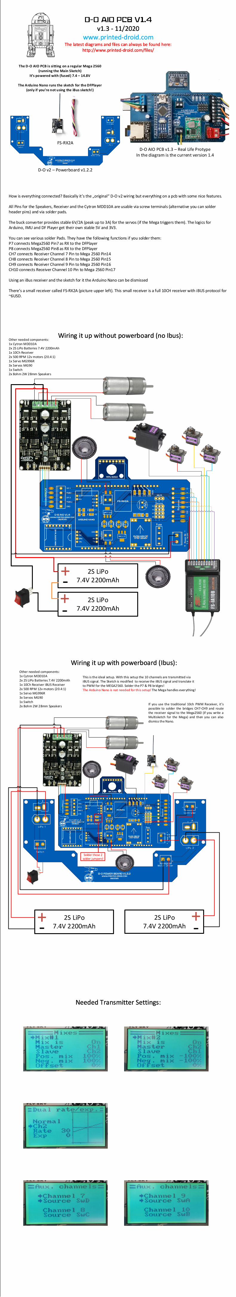
v1.3 - 11/2020 www.printed-droid.com v1.3 - 11/2020 www.printed-droid.com The latest diagrams and files can always be found here: http://www.printed-droid.com/files/ The latest diagrams and files can always be found here: http://www.printed-droid.com/files/ The D-O AIO PCB is sitting on a regular Mega 2560 (running the Main Sketch) Its powered with (fused) 7.4 – 14.8V The Arduino Nano runs the sketch for the DFPlayer (only if youre not using the iBus sketch!) How is everything connected? Basically it s the originalD-O v2 wiring but everything on a pcb with some nice features. All Pins for the Speakers, Receiver and the Cytron MDD10A are usable via screw terminals (alternative you can solder header pins) and via solder pads. The buck converter provides stable 6V/2A (peak up to 3A) for the servos (if the Mega triggers them). The logics for Arduino, IMU and DF Player get their own stable 5V and 3V3. You can see various solder Pads. They have the following functions if you solder them: P7 connects Mega2560 Pin7 as RX to the DFPlayer P8 connects Mega2560 Pin8 as RX to the DFPlayer CH7 connects Receiver Channel 7 Pin to Mega 2560 Pin14 CH8 connects Receiver Channel 8 Pin to Mega 2560 Pin15 CH9 connects Receiver Channel 9 Pin to Mega 2560 Pin16 CH10 connects Receiver Channel 10 Pin to Mega 2560 Pin17 Using an iBus receiver and the sketch for it the Arduino Nano can be dismissed Theres a small receiver called FS-RX2A (picture upper left). This small receiver is a full 10CH receiver with iBUS protocol for ~6USD. Other needed components: 1x Cytron MDD10A 2x 2S LiPo Batteries 7.4V 2200mAh 1x 10Ch Receiver 2x 500 RPM 12v motors (20.4:1) 1x Servo MG996R 3x Servos MG90 1x Switch 2x 8ohm 2W 28mm Speakers D-O AIO PCB v1.3 – Real Life Protype In the diagram is the current version 1.4 Wiring it up without powerboard (no Ibus): Wiring it up without powerboard (no Ibus): 2S LiPo 7.4V 2200mAh 2S LiPo 7.4V 2200mAh + + - - Needed Transmitter Settings: Needed Transmitter Settings: Other needed components: 1x Cytron MDD10A 2x 2S LiPo Batteries 7.4V 2200mAh 1x 10Ch Receiver iBUS Receiver 2x 500 RPM 12v motors (20.4:1) 1x Servo MG996R 3x Servos MG90 1x Switch 2x 8ohm 2W 28mm Speakers Wiring it up with powerboard (Ibus): Wiring it up with powerboard (Ibus): 2S LiPo 7.4V 2200mAh 2S LiPo 7.4V 2200mAh + + - - FS-RX2A D-O v2 – Powerboard v1.2.2 This is the ideal setup. With this setup the 10 channels are transmitted via iBUS signal. The Sketch is modified to receive the iBUS signal and translate it to PWM for the MEGA2560. Solder the P7 & P8 bridges! The Arduino Nano is not needed for this setup! The Mega handles everything! If you use the traditional 10ch PWM Receiver, it s possible to solder the bridges CH7-CH9 and route the receiver signal to the Mega2560 (if you write a Multisketch for the Mega) and then you can also dismiss the Nano. Solder those 2 solder jumpers!
Transcript

v1.3 - 11/2020www.printed-droid.com

v1.3 - 11/2020www.printed-droid.com

The latest diagrams and files can always be found here:http://www.printed-droid.com/files/

The latest diagrams and files can always be found here:http://www.printed-droid.com/files/

The D-O AIO PCB is sitting on a regular Mega 2560(running the Main Sketch)

It’s powered with (fused) 7.4 – 14.8V

The Arduino Nano runs the sketch for the DFPlayer(only if you’re not using the iBus sketch!)

How is everything connected? Basically it’s the „original“ D-O v2 wiring but everything on a pcb with some nice features.

All Pins for the Speakers, Receiver and the Cytron MDD10A are usable via screw terminals (alternative you can solder header pins) and via solder pads.

The buck converter provides stable 6V/2A (peak up to 3A) for the servos (if the Mega triggers them). The logics for Arduino, IMU and DF Player get their own stable 5V and 3V3.

You can see various solder Pads. They have the following functions if you solder them:P7 connects Mega2560 Pin7 as RX to the DFPlayer P8 connects Mega2560 Pin8 as RX to the DFPlayer CH7 connects Receiver Channel 7 Pin to Mega 2560 Pin14CH8 connects Receiver Channel 8 Pin to Mega 2560 Pin15CH9 connects Receiver Channel 9 Pin to Mega 2560 Pin16CH10 connects Receiver Channel 10 Pin to Mega 2560 Pin17

Using an iBus receiver and the sketch for it the Arduino Nano can be dismissed

There’s a small receiver called FS-RX2A (picture upper left). This small receiver is a full 10CH receiver with iBUS protocol for ~6USD.

Other needed components:1x Cytron MDD10A2x 2S LiPo Batteries 7.4V 2200mAh1x 10Ch Receiver2x 500 RPM 12v motors (20.4:1)1x Servo MG996R3x Servos MG901x Switch2x 8ohm 2W 28mm Speakers

D-O AIO PCB v1.3 – Real Life ProtypeIn the diagram is the current version 1.4

Wiring it up without powerboard (no Ibus):Wiring it up without powerboard (no Ibus):

2S LiPo 7.4V 2200mAh

2S LiPo 7.4V 2200mAh

+

+-

-

Needed Transmitter Settings:Needed Transmitter Settings:

Other needed components:1x Cytron MDD10A2x 2S LiPo Batteries 7.4V 2200mAh1x 10Ch Receiver iBUS Receiver2x 500 RPM 12v motors (20.4:1)1x Servo MG996R3x Servos MG901x Switch2x 8ohm 2W 28mm Speakers

Wiring it up with powerboard (Ibus):Wiring it up with powerboard (Ibus):

2S LiPo 7.4V 2200mAh

2S LiPo 7.4V 2200mAh

+ +--

FS-RX2A

D-O v2 – Powerboard v1.2.2

This is the ideal setup. With this setup the 10 channels are transmitted via iBUS signal. The Sketch is modified to receive the iBUS signal and translate it to PWM for the MEGA2560. Solder the P7 & P8 bridges!The Arduino Nano is not needed for this setup! The Mega handles everything!

If you use the traditional 10ch PWM Receiver, it’s possible to solder the bridges CH7-CH9 and route the receiver signal to the Mega2560 (if you write a Multisketch for the Mega) and then you can also dismiss the Nano.

Solder those 2 solder jumpers!

Recommended