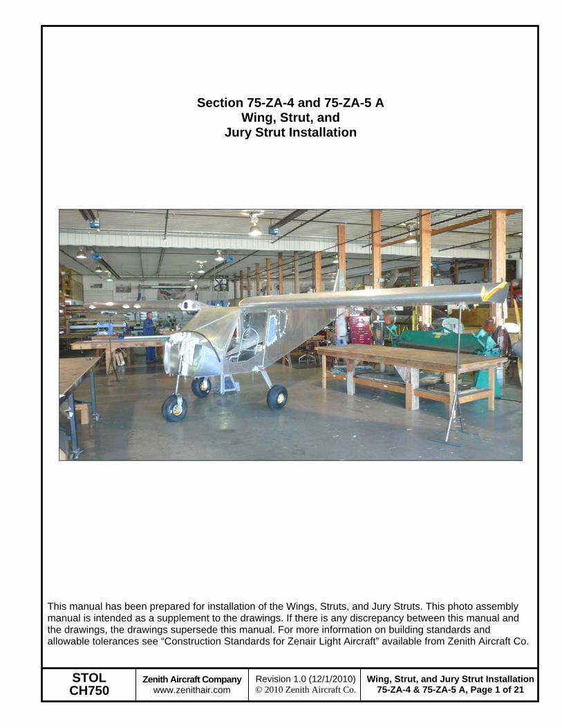
This manual has been prepared for installation of the Wings, Struts, and Jury Struts. This photo assembly manual is intended as a supplement to the drawings. If there is any discrepancy between this manual and the drawings, the drawings supersede this manual. For more information on building standards and allowable tolerances see “Construction Standards for Zenair Light Aircraft” available from Zenith Aircraft Co.
STOL CH750
Zenith Aircraft Company www.zenithair.com
Wing, Strut, and Jury Strut Installation75-ZA-4 & 75-ZA-5 A, Page 2 of 21
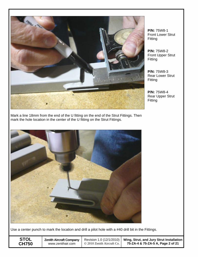
Mark a line 18mm from the end of the U fitting on the end of the Strut Fittings. Then mark the hole location in the center of the U fitting on the Strut Fittings.
Expand the hole in the Strut Fittings to 3/8” in steps. Its best to use a drill press to ensure the holes are perpendicular to the U fittings in the Strut Fittings.
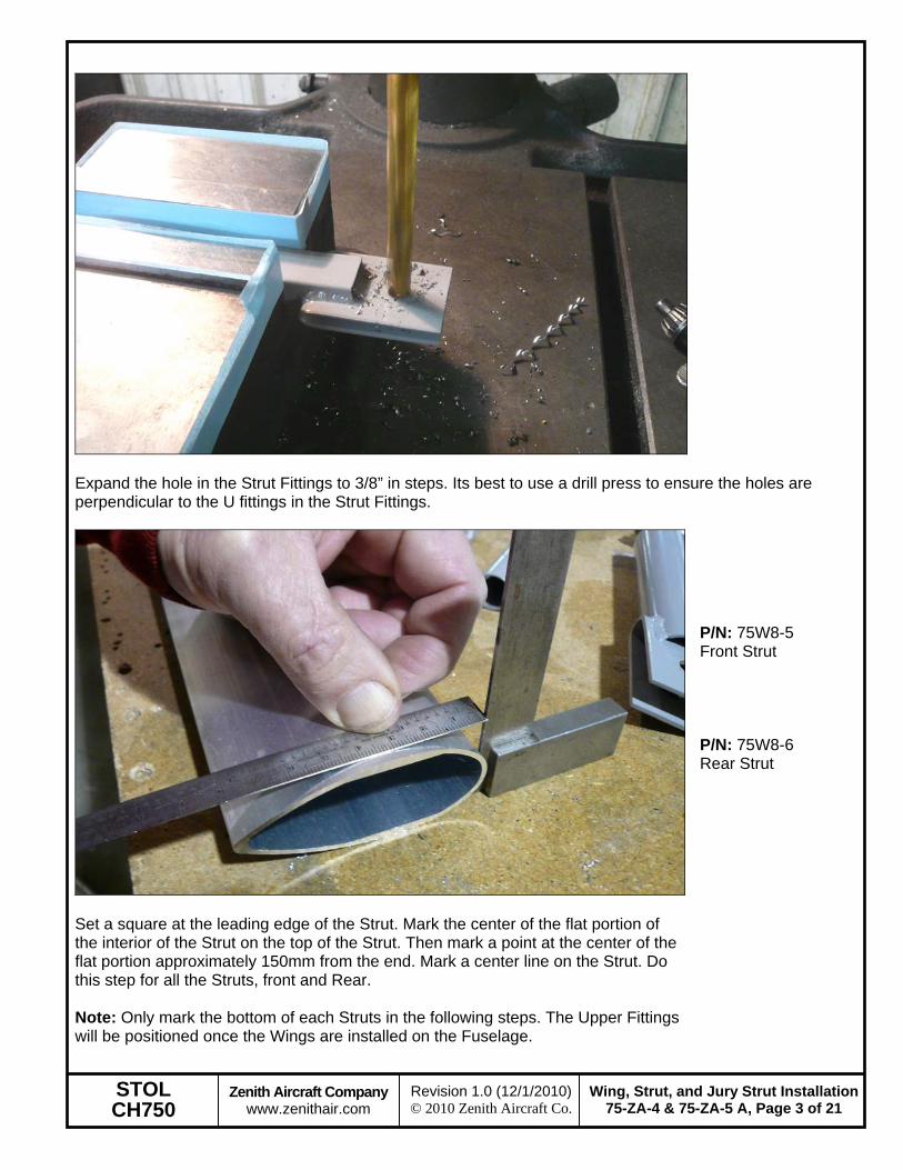
Set a square at the leading edge of the Strut. Mark the center of the flat portion of the interior of the Strut on the top of the Strut. Then mark a point at the center of the flat portion approximately 150mm from the end. Mark a center line on the Strut. Do this step for all the Struts, front and Rear. Note: Only mark the bottom of each Struts in the following steps. The Upper Fittings will be positioned once the Wings are installed on the Fuselage.
P/N: 75W8-5 Front Strut P/N: 75W8-6 Rear Strut
STOL CH750
Zenith Aircraft Company www.zenithair.com
Wing, Strut, and Jury Strut Installation75-ZA-4 & 75-ZA-5 A, Page 4 of 21
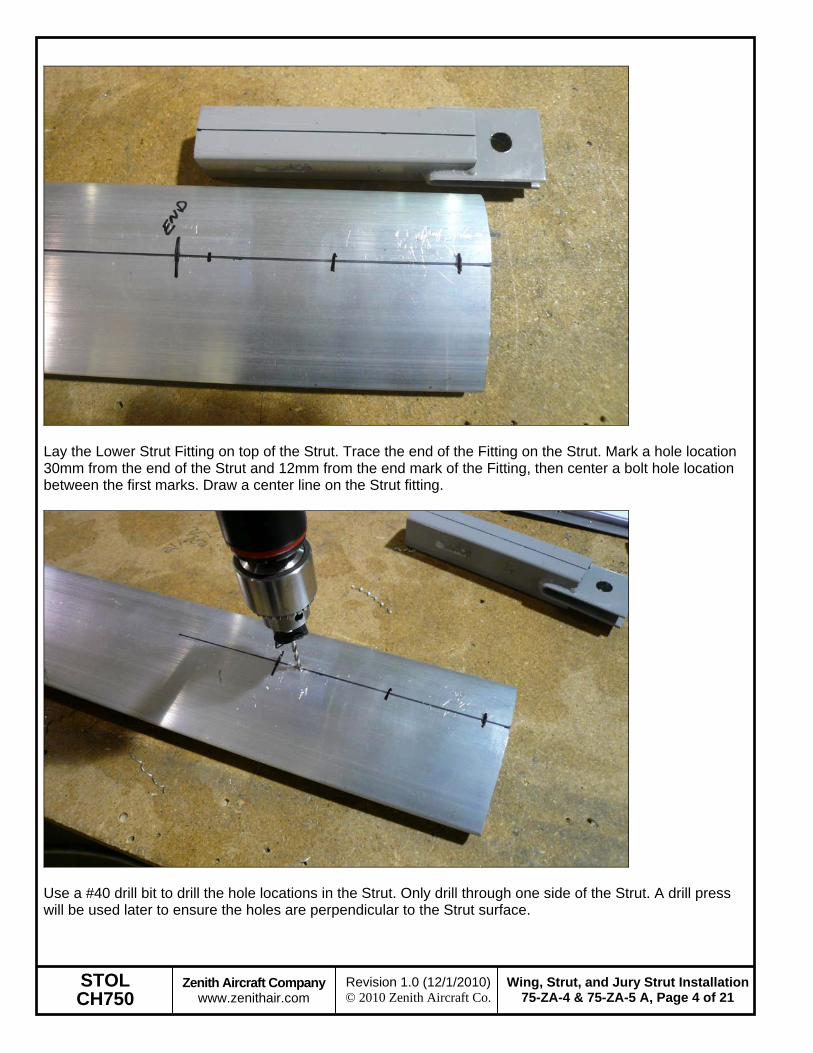
Lay the Lower Strut Fitting on top of the Strut. Trace the end of the Fitting on the Strut. Mark a hole location 30mm from the end of the Strut and 12mm from the end mark of the Fitting, then center a bolt hole location between the first marks. Draw a center line on the Strut fitting.
Use a #40 drill bit to drill the hole locations in the Strut. Only drill through one side of the Strut. A drill press will be used later to ensure the holes are perpendicular to the Strut surface.
STOL CH750
Zenith Aircraft Company www.zenithair.com
Wing, Strut, and Jury Strut Installation75-ZA-4 & 75-ZA-5 A, Page 5 of 21
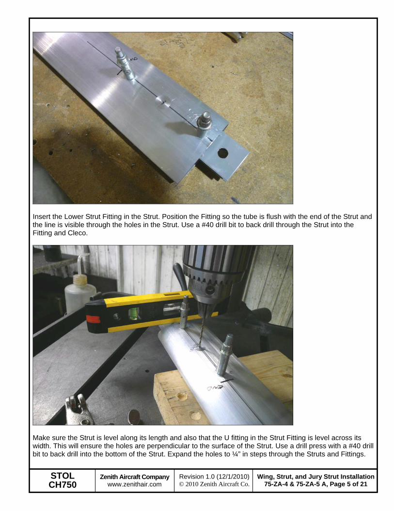
Insert the Lower Strut Fitting in the Strut. Position the Fitting so the tube is flush with the end of the Strut and the line is visible through the holes in the Strut. Use a #40 drill bit to back drill through the Strut into the Fitting and Cleco.
Make sure the Strut is level along its length and also that the U fitting in the Strut Fitting is level across its width. This will ensure the holes are perpendicular to the surface of the Strut. Use a drill press with a #40 drill bit to back drill into the bottom of the Strut. Expand the holes to ¼” in steps through the Struts and Fittings.
STOL CH750
Zenith Aircraft Company www.zenithair.com
Wing, Strut, and Jury Strut Installation75-ZA-4 & 75-ZA-5 A, Page 6 of 21
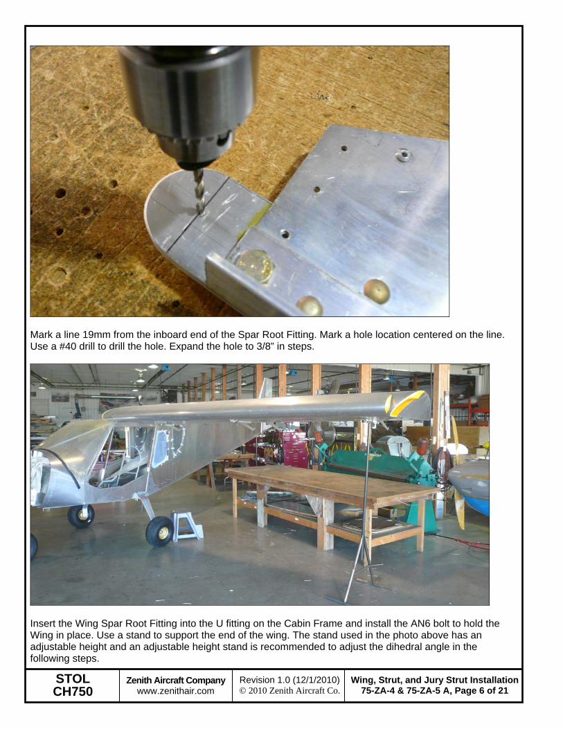
Mark a line 19mm from the inboard end of the Spar Root Fitting. Mark a hole location centered on the line. Use a #40 drill to drill the hole. Expand the hole to 3/8” in steps.
Insert the Wing Spar Root Fitting into the U fitting on the Cabin Frame and install the AN6 bolt to hold the Wing in place. Use a stand to support the end of the wing. The stand used in the photo above has an adjustable height and an adjustable height stand is recommended to adjust the dihedral angle in the following steps.
STOL CH750
Zenith Aircraft Company www.zenithair.com
Wing, Strut, and Jury Strut Installation75-ZA-4 & 75-ZA-5 A, Page 7 of 21
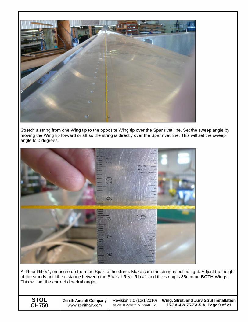
Stretch a string from one Wing tip to the opposite Wing tip over the Spar rivet line. Set the sweep angle by moving the Wing tip forward or aft so the string is directly over the Spar rivet line. This will set the sweep angle to 0 degrees.
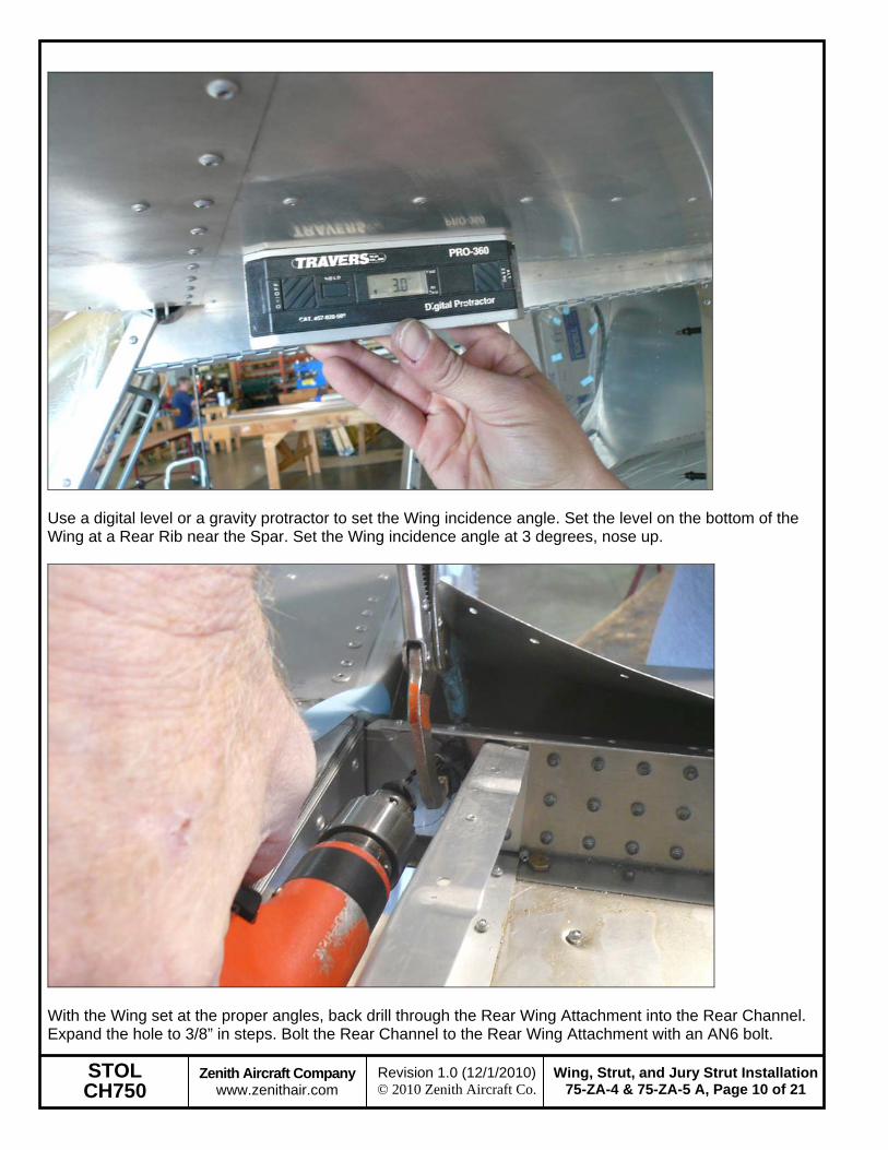
At Rear Rib #1, measure up from the Spar to the string. Make sure the string is pulled tight. Adjust the height of the stands until the distance between the Spar at Rear Rib #1 and the string is 85mm on BOTH Wings. This will set the correct dihedral angle.
STOL CH750
Zenith Aircraft Company www.zenithair.com
Wing, Strut, and Jury Strut Installation75-ZA-4 & 75-ZA-5 A, Page 10 of 21
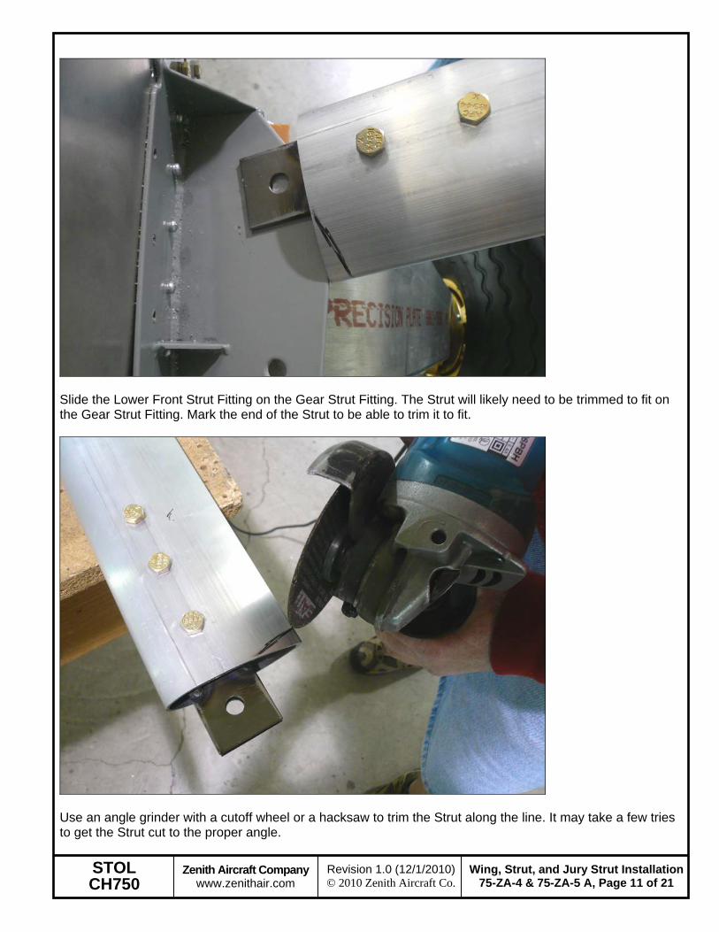
Use a digital level or a gravity protractor to set the Wing incidence angle. Set the level on the bottom of the Wing at a Rear Rib near the Spar. Set the Wing incidence angle at 3 degrees, nose up.
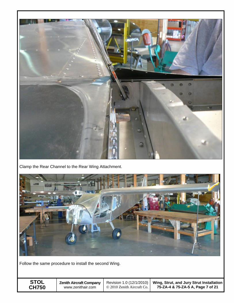
With the Wing set at the proper angles, back drill through the Rear Wing Attachment into the Rear Channel. Expand the hole to 3/8” in steps. Bolt the Rear Channel to the Rear Wing Attachment with an AN6 bolt.
STOL CH750
Zenith Aircraft Company www.zenithair.com
Wing, Strut, and Jury Strut Installation75-ZA-4 & 75-ZA-5 A, Page 11 of 21
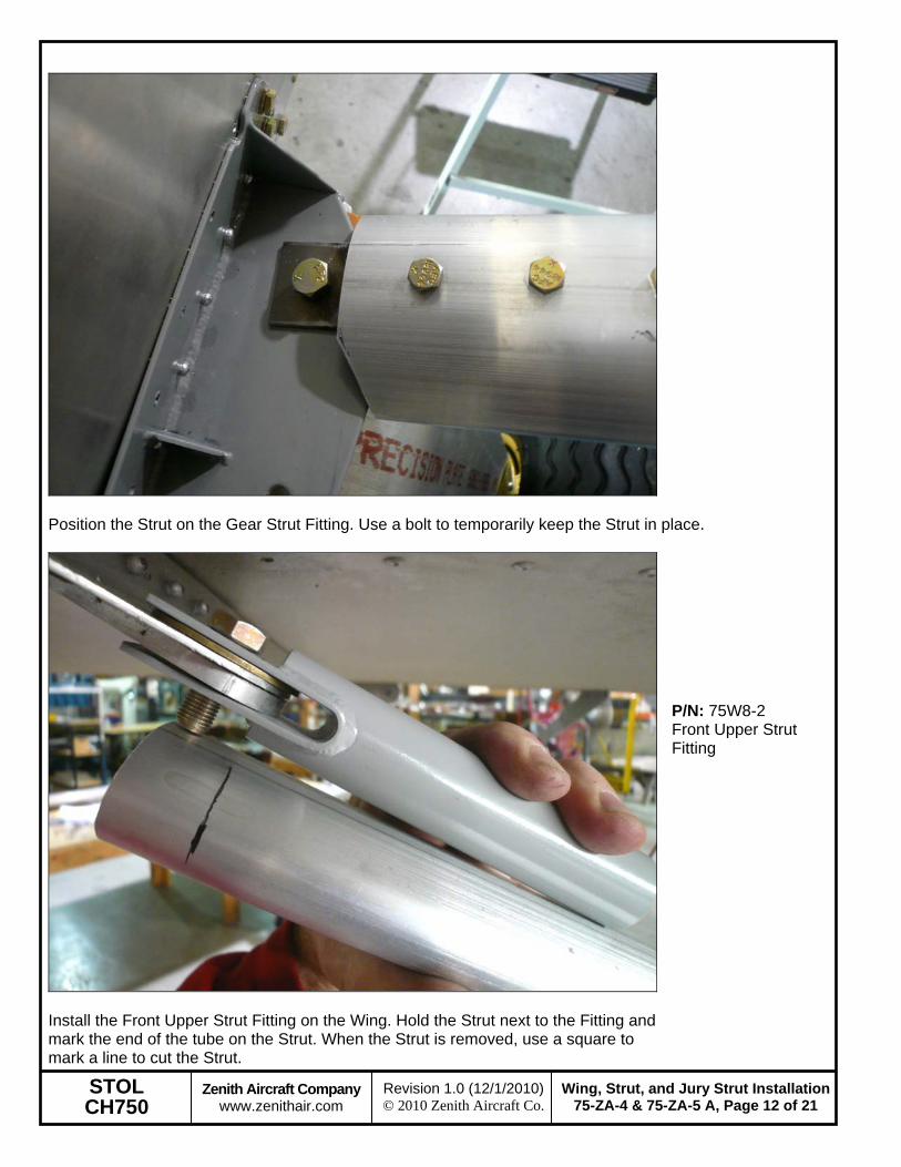
Slide the Lower Front Strut Fitting on the Gear Strut Fitting. The Strut will likely need to be trimmed to fit on the Gear Strut Fitting. Mark the end of the Strut to be able to trim it to fit.
Use an angle grinder with a cutoff wheel or a hacksaw to trim the Strut along the line. It may take a few tries to get the Strut cut to the proper angle.
STOL CH750
Zenith Aircraft Company www.zenithair.com
Wing, Strut, and Jury Strut Installation75-ZA-4 & 75-ZA-5 A, Page 12 of 21
Position the Strut on the Gear Strut Fitting. Use a bolt to temporarily keep the Strut in place.
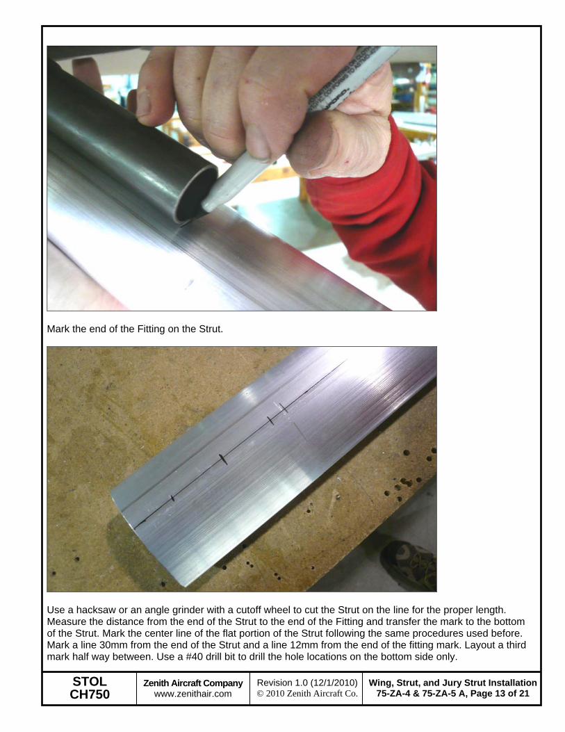
Install the Front Upper Strut Fitting on the Wing. Hold the Strut next to the Fitting and mark the end of the tube on the Strut. When the Strut is removed, use a square to mark a line to cut the Strut.
P/N: 75W8-2 Front Upper Strut Fitting
STOL CH750
Zenith Aircraft Company www.zenithair.com
Wing, Strut, and Jury Strut Installation75-ZA-4 & 75-ZA-5 A, Page 13 of 21
Use a hacksaw or an angle grinder with a cutoff wheel to cut the Strut on the line for the proper length. Measure the distance from the end of the Strut to the end of the Fitting and transfer the mark to the bottom of the Strut. Mark the center line of the flat portion of the Strut following the same procedures used before. Mark a line 30mm from the end of the Strut and a line 12mm from the end of the fitting mark. Layout a third mark half way between. Use a #40 drill bit to drill the hole locations on the bottom side only.
STOL CH750
Zenith Aircraft Company www.zenithair.com
Wing, Strut, and Jury Strut Installation75-ZA-4 & 75-ZA-5 A, Page 14 of 21
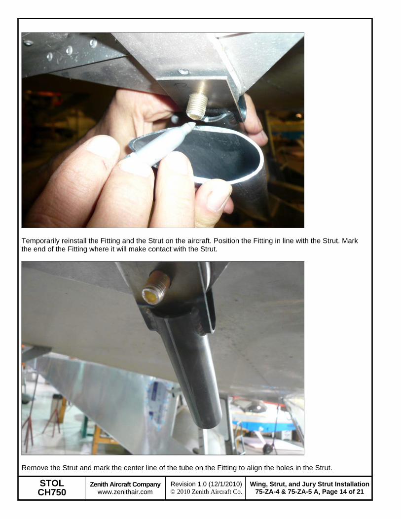
Temporarily reinstall the Fitting and the Strut on the aircraft. Position the Fitting in line with the Strut. Mark the end of the Fitting where it will make contact with the Strut.
Remove the Strut and mark the center line of the tube on the Fitting to align the holes in the Strut.
STOL CH750
Zenith Aircraft Company www.zenithair.com
Wing, Strut, and Jury Strut Installation75-ZA-4 & 75-ZA-5 A, Page 15 of 21
Slide the Upper Fitting into the Strut, be careful not to lose the Fitting in the Strut. Reinstall the Strut on the aircraft. The Wing will likely have to be lifted to be able to slide the Strut into place at the Wing. Insert a bolt to hold the Fitting in place. Align the center line mark on the Fitting through the holes in the Strut. Use a clamp to hold the Fitting in place inside the Strut.
Use a #40 drill bit to back drill through the Strut into the Fitting and Cleco. Only drill through the bottom side, the holes will be drilled through the top on a drill press to ensure they are in line.
STOL CH750
Zenith Aircraft Company www.zenithair.com
Wing, Strut, and Jury Strut Installation75-ZA-4 & 75-ZA-5 A, Page 16 of 21
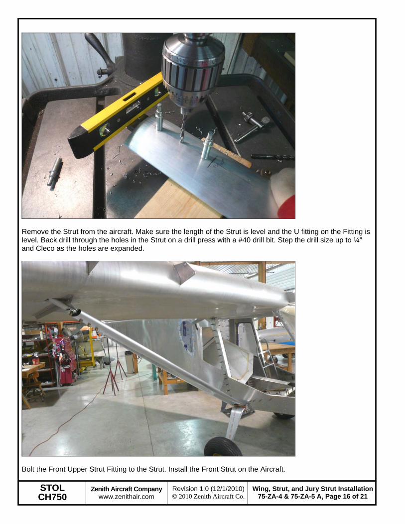
Remove the Strut from the aircraft. Make sure the length of the Strut is level and the U fitting on the Fitting is level. Back drill through the holes in the Strut on a drill press with a #40 drill bit. Step the drill size up to ¼” and Cleco as the holes are expanded.
Bolt the Front Upper Strut Fitting to the Strut. Install the Front Strut on the Aircraft.
STOL CH750
Zenith Aircraft Company www.zenithair.com
Wing, Strut, and Jury Strut Installation75-ZA-4 & 75-ZA-5 A, Page 17 of 21
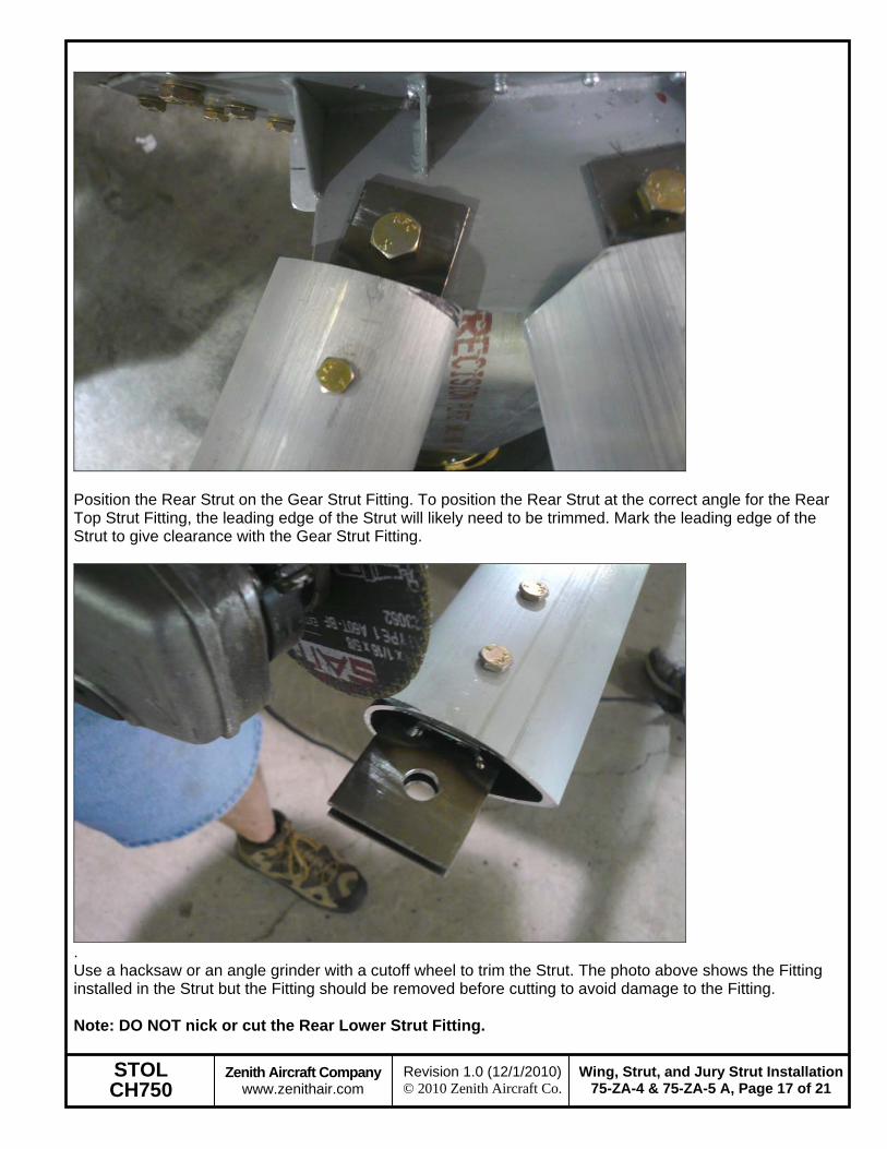
Position the Rear Strut on the Gear Strut Fitting. To position the Rear Strut at the correct angle for the Rear Top Strut Fitting, the leading edge of the Strut will likely need to be trimmed. Mark the leading edge of the Strut to give clearance with the Gear Strut Fitting.
. Use a hacksaw or an angle grinder with a cutoff wheel to trim the Strut. The photo above shows the Fitting installed in the Strut but the Fitting should be removed before cutting to avoid damage to the Fitting. Note: DO NOT nick or cut the Rear Lower Strut Fitting.
STOL CH750
Zenith Aircraft Company www.zenithair.com
Wing, Strut, and Jury Strut Installation75-ZA-4 & 75-ZA-5 A, Page 18 of 21
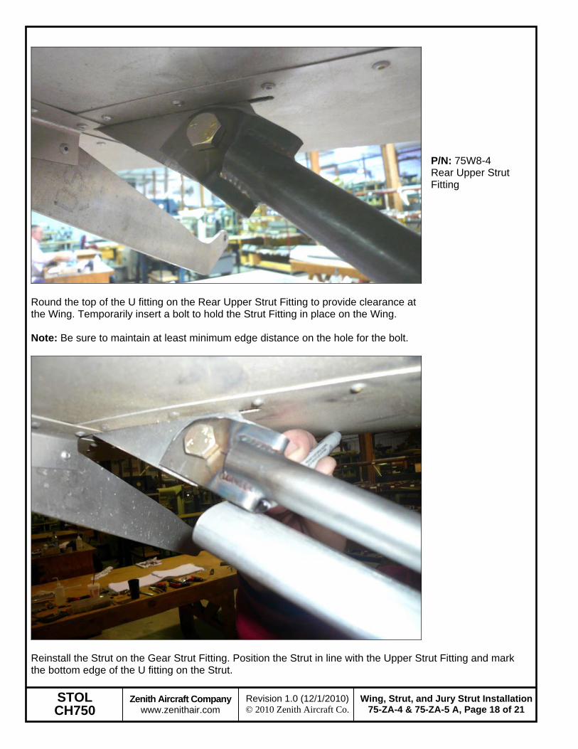
Round the top of the U fitting on the Rear Upper Strut Fitting to provide clearance at the Wing. Temporarily insert a bolt to hold the Strut Fitting in place on the Wing. Note: Be sure to maintain at least minimum edge distance on the hole for the bolt.
P/N: 75W8-4 Rear Upper Strut Fitting
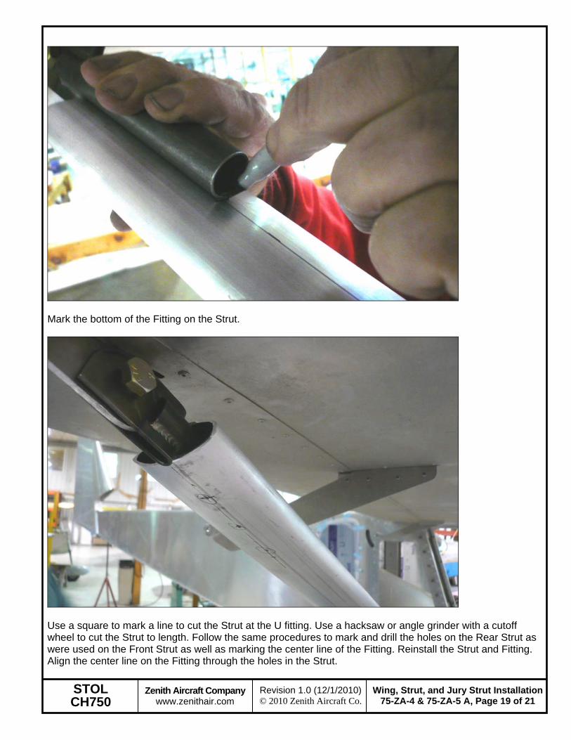
Reinstall the Strut on the Gear Strut Fitting. Position the Strut in line with the Upper Strut Fitting and mark the bottom edge of the U fitting on the Strut.
STOL CH750
Zenith Aircraft Company www.zenithair.com
Wing, Strut, and Jury Strut Installation75-ZA-4 & 75-ZA-5 A, Page 19 of 21
Use a square to mark a line to cut the Strut at the U fitting. Use a hacksaw or angle grinder with a cutoff wheel to cut the Strut to length. Follow the same procedures to mark and drill the holes on the Rear Strut as were used on the Front Strut as well as marking the center line of the Fitting. Reinstall the Strut and Fitting. Align the center line on the Fitting through the holes in the Strut.
STOL CH750
Zenith Aircraft Company www.zenithair.com
Wing, Strut, and Jury Strut Installation75-ZA-4 & 75-ZA-5 A, Page 20 of 21
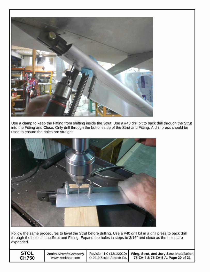
Use a clamp to keep the Fitting from shifting inside the Strut. Use a #40 drill bit to back drill through the Strut into the Fitting and Cleco. Only drill through the bottom side of the Strut and Fitting. A drill press should be used to ensure the holes are straight.
Follow the same procedures to level the Strut before drilling. Use a #40 drill bit in a drill press to back drill through the holes in the Strut and Fitting. Expand the holes in steps to 3/16” and cleco as the holes are expanded.
STOL CH750
Zenith Aircraft Company www.zenithair.com
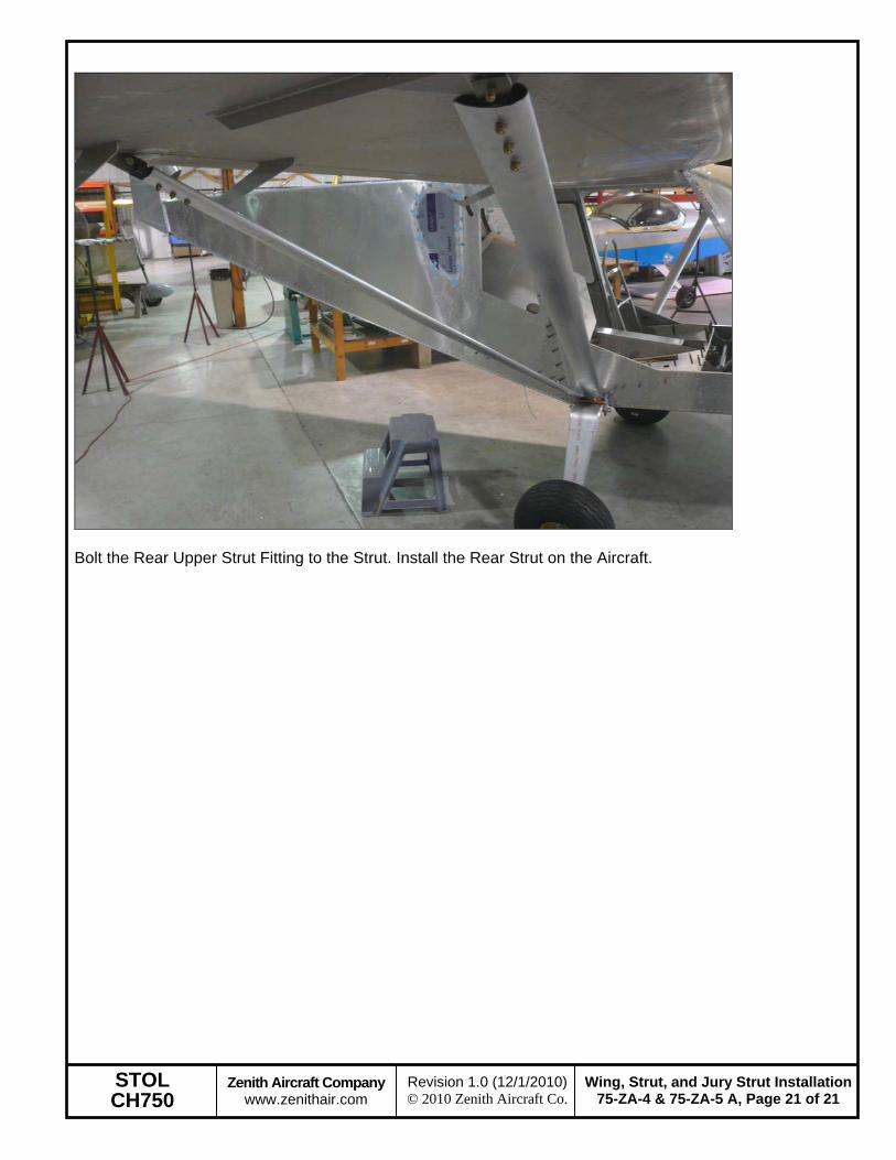
Wing, Strut, and Jury Strut Installation75-ZA-4 & 75-ZA-5 A, Page 21 of 21