Olympia Chimney Supply, Inc., 600 Sanders Street, Scranton, PA 18505 (570) 496-8890 Ventis® Class-A All-Fuel Chimney System INSTALLATION INSTRUCTIONS A MAJOR CAUSE OF CHIMNEY RELATED FIRES IS FAILURE TO MAINTAIN REQUIRED CLEARANCES (AIR SPACES) TO COMBUSTIBLE MATERIALS. IT IS OF THE UTMOST IMPORTANCE THAT THIS CHIMNEY BE INSTALLED ONLY IN ACCORDANCE WITH THESE INSTRUCTIONS.
Transcript
Olympia Chimney Supply, Inc., 600 Sanders Street, Scranton, PA 18505
(570) 496-8890
Ventis® Class-AAll-Fuel Chimney System
InStAllAtIon InStruCtIonS
A mAjor CAuSe oF ChImney relAted FIreS IS FAIlure to mAIntAIn requIred CleArAnCeS (AIr SpACeS) to CombuStIble mAterIAlS. It IS oF the utmoSt
ImportAnCe thAt thIS ChImney be InStAlled only In ACCordAnCe wIth theSe InStruCtIonS.
V e n t i s C l a s s - a i n s t a l l a t i o n i n s t r u C t i o n s2
The quality and workmanship of Ventis Class-A is reflected in the recognition Underwriters Laboratories has given these products. The rigorous UL testing and listing requirements, is your assurance of consistent quality in materials and manufacturing standards used for this chimney system.
In addition, the industry leading Warranty on Ventis Class-A is a further indication of our confidence in the quality of these products. Thank you for choosing Ventis!
The Ventis Class-A chimney system is UL 103HT listed to 2100 degrees up to 8” diameter.
The chimney system must be installed by a qualified chimney or venting professional according to these installation and maintenance instructions. Read through and become familiar with these installation instructions before installing this product. Failure to follow these instructions may void the manufacturer’s warranty and the UL listing status of this product.
Codes & permits The criteria for installation must be in conformance with the specifications contained in the latest version of the NFPA 211 (Standard for Chimneys, Fireplaces, Vents and Solid Fuel Burning Appliances) and local or state building codes, whichever has jurisdiction. Contact local building or fire officials about restrictions and installation inspection in your area. It may be necessary to obtain permits before installing the chimney system. ALWAYS CONTACT YOUR LOCAL BUILDING OFFICIAL OR FIRE OFFICIAL REGARDING PERMITS, RESTRICTIONS AND INSTALLATION INSPECTIONS IN YOUR AREA.
product Applications The Ventis Class-A Chimney system is intended for use with heating appliances utilizing solid fuels, oil, gas (natural or propane) and coal. This includes, but is not limited to, the following appliance types: free standing wood stoves, wood stove inserts, fireboxes, fireplaces, furnaces, boilers, stoves, ranges or water heaters that require a UL103 HT chimney system. Ventis Class-A is not listed, nor intended, to be installed with forced draft or positive pressure heating appliances.
General product Information
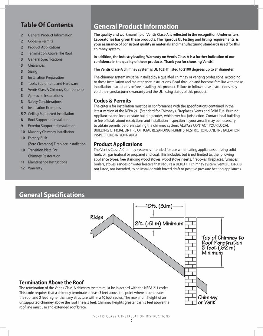
termination Above the roofThe termination of the Ventis Class-A chimney system must be in accord with the NFPA 211 codes. This code requires that a chimney terminate at least 3 feet above the point where it penetrates the roof and 2 feet higher than any structure within a 10 foot radius. The maximum height of an unsupported chimney above the roof line is 5 feet. Chimney heights greater than 5 feet above the roof line must use and extended roof brace.
Top of Chimney to Roof Penetration 3 feet (.92 m)Minimum
Ridge
10ft. (3.lm)
2ft. (.6l m) Minimum
Chimneyor Vent
General Specifications
table of Contents2 General Product Information 2 Codes & Permits2 Product Applications2 Termination Above The Roof 3 General Specifications 3 Clearances3 Sizing3 Installation Preparation3 Tools, Equipment, and Hardware3 Ventis Class A Chimney Components3 Approved Installations3 Safety Considerations4 Installation Examples 5-7 Ceiling Supported Installation 8 Roof Supported Installation9 Exterior Supported Installation10 Masonry Chimney Installation10 Factory Built (Zero Clearance) Fireplace Installation 10 Transition Plate For Chimney Restoration 11 Maintenance Instructions12 Warranty
V e n t i s C l a s s - a i n s t a l l a t i o n i n s t r u C t i o n s3
Clearances A minimum 2 inch airspace must be maintained between the exterior of the Ventis Class-A chimney system and combustible materials or as established by factory built supports and firestops. Ensure that building insulation, electrical wiring and/or any other combustible materials do not violate the required 2-inch airspace clearance.
The clearance between single wall connector pipe (VENTIS BLACK™ SINGLE WALL STOVEPIPE) and unprotected combustible material must not be less than 18-inches (See latest version of NFPA 211). The distance between the vertical single wall stove pipe and the ceiling may be less than 18-inches depending on the specifications of the finishing support. For double wall connector pipe (VENTIS BLACK™ DOUBLE WALL STOVEPIPE) the clearance to unprotected combustible material must not be less than 6-inches to vertical walls and 8-inches to the ceiling (See latest version of NFPA 211). The distance between the vertical double wall stove pipe and the ceiling may be less than 8-inches depending on the specifications of the finishing support.
For installing the chimney system in a chase application, the chimney must extend a minimum of 36-inches above the chase cover.
Sizing the Chimney Systems Always size the chimney liner in accordance with the appliance manufacturer’s instructions. Keep in mind that the outside diameter will be 2 1/2-inches larger than the inside diameter. The Ventis Class-A chimney system may be installed to a maximum height of 60 feet.
Additional Considerations It is recommended, in colder climates, that exterior mounted chimney systems are enclosed to help reduce or limit condensation, creosote build-up and poor draft.
General product Information General Specifications (Continued)
tools, equipment, and hardwareTools: EquipmEnT: HardwarE:Reciprocating Saw Plumb Bob Hammer Ladder #8–1 ½” & 2 ½” ScrewsKeyhole Saw Level Caulk Gun Safety Glasses Framing NailsDrill Tape Measure Screwdrivers Protective Gloves Roofing Nails Metal Snips High-Temp Sealant
Ventis Class-A Chimney Components (part no.)
Anchor Plate(VA-APxx)
Attic Insulation Shield(VA-AISxx)
Ceiling Support - Round(VA-CCRyyxx)
Ceiling Support - Square(VA-CCSyyxx)
Round Ceiling Trim Collar(VA-CRTxxvv)
Elbow/Offset Support(VA-ELS58)
Elbow – 15 degree(VA-ELxx15)
Elbow - 30 degree(VA-ELxx30)
Firestop/Radiation Shield(VA-FSxx)
Chimney Pipe(VAzzz-xxyy)
Rain Cap(VA-Cxx)
Roof Support(VA-RS58)
Tee w/ Tee Cap(VAzzz-Txx)
Telescoping Pipe(VAzzz-ALPxx)
(VAzzz-ALPxx)Universal Adapter
Extended Roof Brace(VA-RB58)
Roof Flashing – Flat(VA-FFLxx)
Roof Flashing - Pitched(VA-Fxxvv)
Storm Collar(VA-SC58)
Masonry Transition Plate(VA-TPxx)
Wall Support(VA-WS58)
Extended Wall Support(VA-WSE58)
Wall Pass-Thru - Thimble(VA-WPTxx)
(Thimble) Finishing Collar(VA-FCxx)
Note: xx = diameter; yy = length; zzz = type of stainless steel (inner pipe); vv = pitch
Approved Installations Use of any parts or materials not specified in this installation manual may not provide a listed system and may void the Ventis Class-A warranty. Do not attempt matching Ventis components or pipe sections with another manufacturer’s products. Do not use damaged or modified parts.
Safety Considerations Caution: The ends of the chimney sections, edges of the cap, roof flashings, tee and other components can be sharp! We strongly recommend the use of gloves during installation.
Installation preparation
warning: Watch out for overhead power lines during installation. Be sure to check above and around the chimney for antennas, power lines, or any other obstacles before beginning the installation. Be sure that the chimney does not come in contact with electrical or any other wires.
note:Except for the installation in one and two-family dwellings, a factory-built chimney that extends through any zone above that on which the connected appliance is located is to be provided with an enclosure having a fire resistance rating equal to or greater than that of the floor or roof assemblies through which it passes.
V e n t i s C l a s s - a i n s t a l l a t i o n i n s t r u C t i o n s4
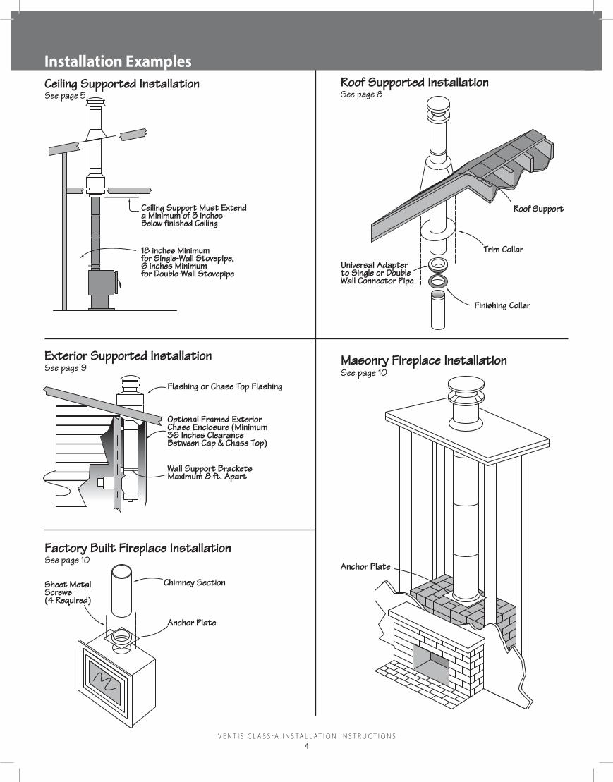
Installation examples
Ceiling Support Must Extend a Minimum of 3 inchesBelow finished Ceiling
V e n t i s C l a s s - a i n s t a l l a t i o n i n s t r u C t i o n s5
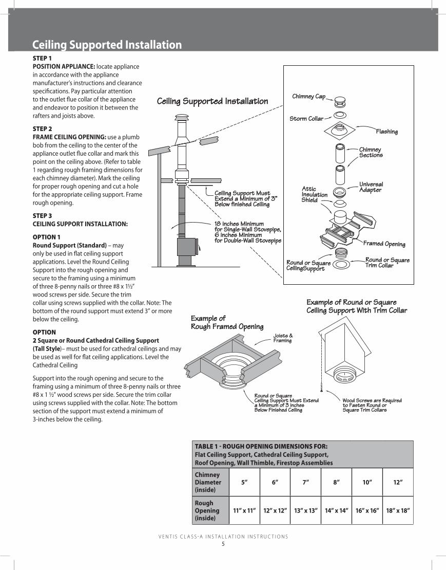
Installation examples Ceiling Supported InstallationsTEp 1 poSItIon ApplIAnCe: locate appliance in accordance with the appliance manufacturer’s instructions and clearance specifications. Pay particular attention to the outlet flue collar of the appliance and endeavor to position it between the rafters and joists above.
sTEp 2 FrAme CeIlInG openInG: use a plumb bob from the ceiling to the center of the appliance outlet flue collar and mark this point on the ceiling above. (Refer to table 1 regarding rough framing dimensions for each chimney diameter). Mark the ceiling for proper rough opening and cut a hole for the appropriate ceiling support. Frame rough opening.
sTEp 3 CeIlInG Support InStAllAtIon:
opTion 1 round Support (Standard) – may only be used in flat ceiling support applications. Level the Round Ceiling Support into the rough opening and secure to the framing using a minimum of three 8-penny nails or three #8 x 1½” wood screws per side. Secure the trim collar using screws supplied with the collar. Note: The bottom of the round support must extend 3” or more below the ceiling.
opTion 2 Square or round Cathedral Ceiling Support (tall Style)– must be used for cathedral ceilings and may be used as well for flat ceiling applications. Level the Cathedral Ceiling
Support into the rough opening and secure to the framing using a minimum of three 8-penny nails or three #8 x 1 ½” wood screws per side. Secure the trim collar using screws supplied with the collar. Note: The bottom section of the support must extend a minimum of 3-inches below the ceiling.
Chimney Cap
Storm Collar
Flashing
ChimneySections
AtticInsulation Shield
Framed Opening
Round or Square CeilingSupport
Round or Square Trim Collar
Ceiling Support Must Extend a Minimum of 3”Below finished Ceiling
11” x 11” 12” x 12” 13” x 13” 14” x 14” 16” x 16” 18” x 18”
V e n t i s C l a s s - a i n s t a l l a t i o n i n s t r u C t i o n s6
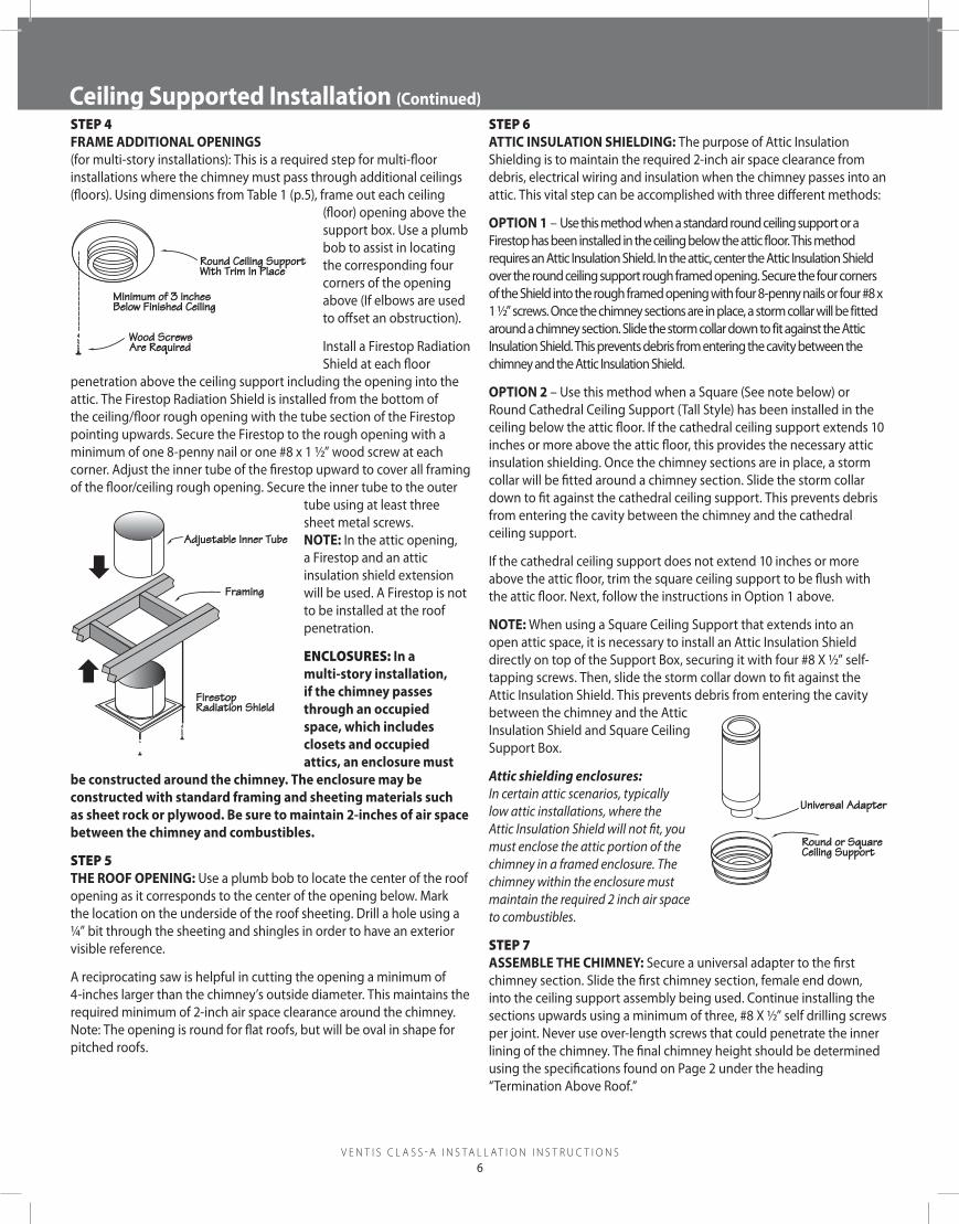
Ceiling Supported Installation (Continued)sTEp 4 FrAme AddItIonAl openInGS (for multi-story installations): This is a required step for multi-floor installations where the chimney must pass through additional ceilings (floors). Using dimensions from Table 1 (p.5), frame out each ceiling
(floor) opening above the support box. Use a plumb bob to assist in locating the corresponding four corners of the opening above (If elbows are used to offset an obstruction).
Install a Firestop Radiation Shield at each floor
penetration above the ceiling support including the opening into the attic. The Firestop Radiation Shield is installed from the bottom of the ceiling/floor rough opening with the tube section of the Firestop pointing upwards. Secure the Firestop to the rough opening with a minimum of one 8-penny nail or one #8 x 1 ½” wood screw at each corner. Adjust the inner tube of the firestop upward to cover all framing of the floor/ceiling rough opening. Secure the inner tube to the outer
tube using at least three sheet metal screws. note: In the attic opening, a Firestop and an attic insulation shield extension will be used. A Firestop is not to be installed at the roof penetration.
EnClosurEs: In a multi-story installation, if the chimney passes through an occupied space, which includes closets and occupied attics, an enclosure must
be constructed around the chimney. the enclosure may be constructed with standard framing and sheeting materials such as sheet rock or plywood. be sure to maintain 2-inches of air space between the chimney and combustibles.
sTEp 5 the rooF openInG: Use a plumb bob to locate the center of the roof opening as it corresponds to the center of the opening below. Mark the location on the underside of the roof sheeting. Drill a hole using a ¼” bit through the sheeting and shingles in order to have an exterior visible reference.
A reciprocating saw is helpful in cutting the opening a minimum of 4-inches larger than the chimney’s outside diameter. This maintains the required minimum of 2-inch air space clearance around the chimney. Note: The opening is round for flat roofs, but will be oval in shape for pitched roofs.
sTEp 6AttIC InSulAtIon ShIeldInG: The purpose of Attic Insulation Shielding is to maintain the required 2-inch air space clearance from debris, electrical wiring and insulation when the chimney passes into an attic. This vital step can be accomplished with three different methods:
optIon 1 – Use this method when a standard round ceiling support or a Firestop has been installed in the ceiling below the attic floor. This method requires an Attic Insulation Shield. In the attic, center the Attic Insulation Shield over the round ceiling support rough framed opening. Secure the four corners of the Shield into the rough framed opening with four 8-penny nails or four #8 x 1 ½” screws. Once the chimney sections are in place, a storm collar will be fitted around a chimney section. Slide the storm collar down to fit against the Attic Insulation Shield. This prevents debris from entering the cavity between the chimney and the Attic Insulation Shield.
optIon 2 – Use this method when a Square (See note below) or Round Cathedral Ceiling Support (Tall Style) has been installed in the ceiling below the attic floor. If the cathedral ceiling support extends 10 inches or more above the attic floor, this provides the necessary attic insulation shielding. Once the chimney sections are in place, a storm collar will be fitted around a chimney section. Slide the storm collar down to fit against the cathedral ceiling support. This prevents debris from entering the cavity between the chimney and the cathedral ceiling support.
If the cathedral ceiling support does not extend 10 inches or more above the attic floor, trim the square ceiling support to be flush with the attic floor. Next, follow the instructions in Option 1 above.
note: When using a Square Ceiling Support that extends into an open attic space, it is necessary to install an Attic Insulation Shield directly on top of the Support Box, securing it with four #8 X ½” self-tapping screws. Then, slide the storm collar down to fit against the Attic Insulation Shield. This prevents debris from entering the cavity between the chimney and the Attic Insulation Shield and Square Ceiling Support Box.
Attic shielding enclosures: In certain attic scenarios, typically low attic installations, where the Attic Insulation Shield will not fit, you must enclose the attic portion of the chimney in a framed enclosure. The chimney within the enclosure must maintain the required 2 inch air space to combustibles.
sTEp 7ASSemble the ChImney: Secure a universal adapter to the first chimney section. Slide the first chimney section, female end down, into the ceiling support assembly being used. Continue installing the sections upwards using a minimum of three, #8 X ½” self drilling screws per joint. Never use over-length screws that could penetrate the inner lining of the chimney. The final chimney height should be determined using the specifications found on Page 2 under the heading “Termination Above Roof.”
Wood ScrewsAre Required
Round Ceiling SupportWith Trim In Place
Minimum of 3 inchesBelow Finished Ceiling
Framing
FirestopRadiation Shield
Adjustable Inner Tube
Universal Adapter
Round or Square Ceiling Support
V e n t i s C l a s s - a i n s t a l l a t i o n i n s t r u C t i o n s7
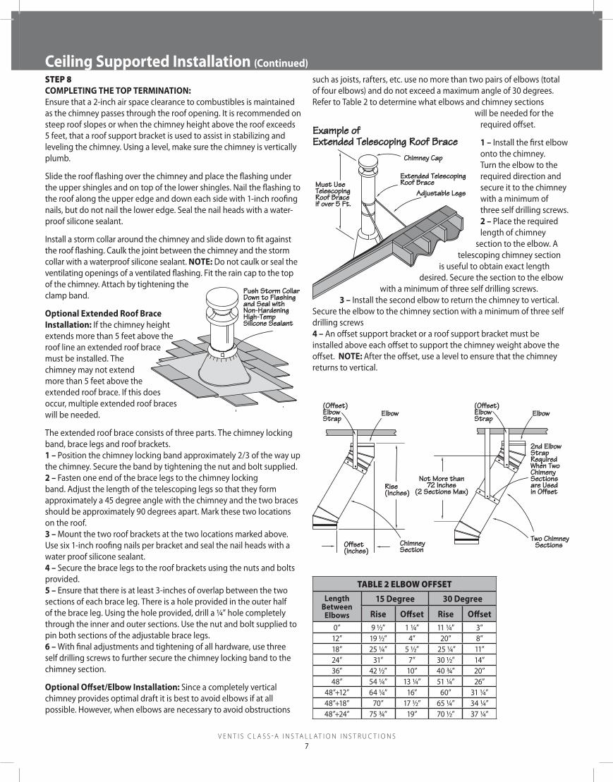
Ceiling Supported Installation (Continued) Ceiling Supported Installation (Continued)sTEp 8 CompletInG the top termInAtIon:Ensure that a 2-inch air space clearance to combustibles is maintained as the chimney passes through the roof opening. It is recommended on steep roof slopes or when the chimney height above the roof exceeds 5 feet, that a roof support bracket is used to assist in stabilizing and leveling the chimney. Using a level, make sure the chimney is vertically plumb.
Slide the roof flashing over the chimney and place the flashing under the upper shingles and on top of the lower shingles. Nail the flashing to the roof along the upper edge and down each side with 1-inch roofing nails, but do not nail the lower edge. Seal the nail heads with a water-proof silicone sealant.
Install a storm collar around the chimney and slide down to fit against the roof flashing. Caulk the joint between the chimney and the storm collar with a waterproof silicone sealant. note: Do not caulk or seal the ventilating openings of a ventilated flashing. Fit the rain cap to the top of the chimney. Attach by tightening the clamp band.
optional extended roof brace Installation: If the chimney height extends more than 5 feet above the roof line an extended roof brace must be installed. The chimney may not extend more than 5 feet above the extended roof brace. If this does occur, multiple extended roof braces will be needed.
The extended roof brace consists of three parts. The chimney locking band, brace legs and roof brackets. 1 – Position the chimney locking band approximately 2/3 of the way up the chimney. Secure the band by tightening the nut and bolt supplied. 2 – Fasten one end of the brace legs to the chimney locking band. Adjust the length of the telescoping legs so that they form approximately a 45 degree angle with the chimney and the two braces should be approximately 90 degrees apart. Mark these two locations on the roof. 3 – Mount the two roof brackets at the two locations marked above. Use six 1-inch roofing nails per bracket and seal the nail heads with a water proof silicone sealant. 4 – Secure the brace legs to the roof brackets using the nuts and bolts provided. 5 – Ensure that there is at least 3-inches of overlap between the two sections of each brace leg. There is a hole provided in the outer half of the brace leg. Using the hole provided, drill a ¼” hole completely through the inner and outer sections. Use the nut and bolt supplied to pin both sections of the adjustable brace legs. 6 – With final adjustments and tightening of all hardware, use three self drilling screws to further secure the chimney locking band to the chimney section.
optional offset/elbow Installation: Since a completely vertical chimney provides optimal draft it is best to avoid elbows if at all possible. However, when elbows are necessary to avoid obstructions
such as joists, rafters, etc. use no more than two pairs of elbows (total of four elbows) and do not exceed a maximum angle of 30 degrees. Refer to Table 2 to determine what elbows and chimney sections
will be needed for the required offset.
1 – Install the first elbow onto the chimney. Turn the elbow to the required direction and secure it to the chimney with a minimum of three self drilling screws. 2 – Place the required length of chimney
section to the elbow. A telescoping chimney section
is useful to obtain exact length desired. Secure the section to the elbow
with a minimum of three self drilling screws. 3 – Install the second elbow to return the chimney to vertical.
Secure the elbow to the chimney section with a minimum of three self drilling screws 4 – An offset support bracket or a roof support bracket must be installed above each offset to support the chimney weight above the offset. note: After the offset, use a level to ensure that the chimney returns to vertical.
Push Storm Collar Down to Flashingand Seal with Non-Hardening High-Temp Silicone Sealant
Must Use Telescoping Roof Brace if over 5 Ft.
Chimney Cap
Extended Telescoping Roof Brace
Adjustable Legs
Example of Extended Telescoping Roof Brace
Offset(inches)
ChimneySection
Rise(Inches)
Elbow(Offset)ElbowStrap
Elbow
2nd ElbowStrap Required When Two Chimeny Sections are Used in Offset
V e n t i s C l a s s - a i n s t a l l a t i o n i n s t r u C t i o n s8
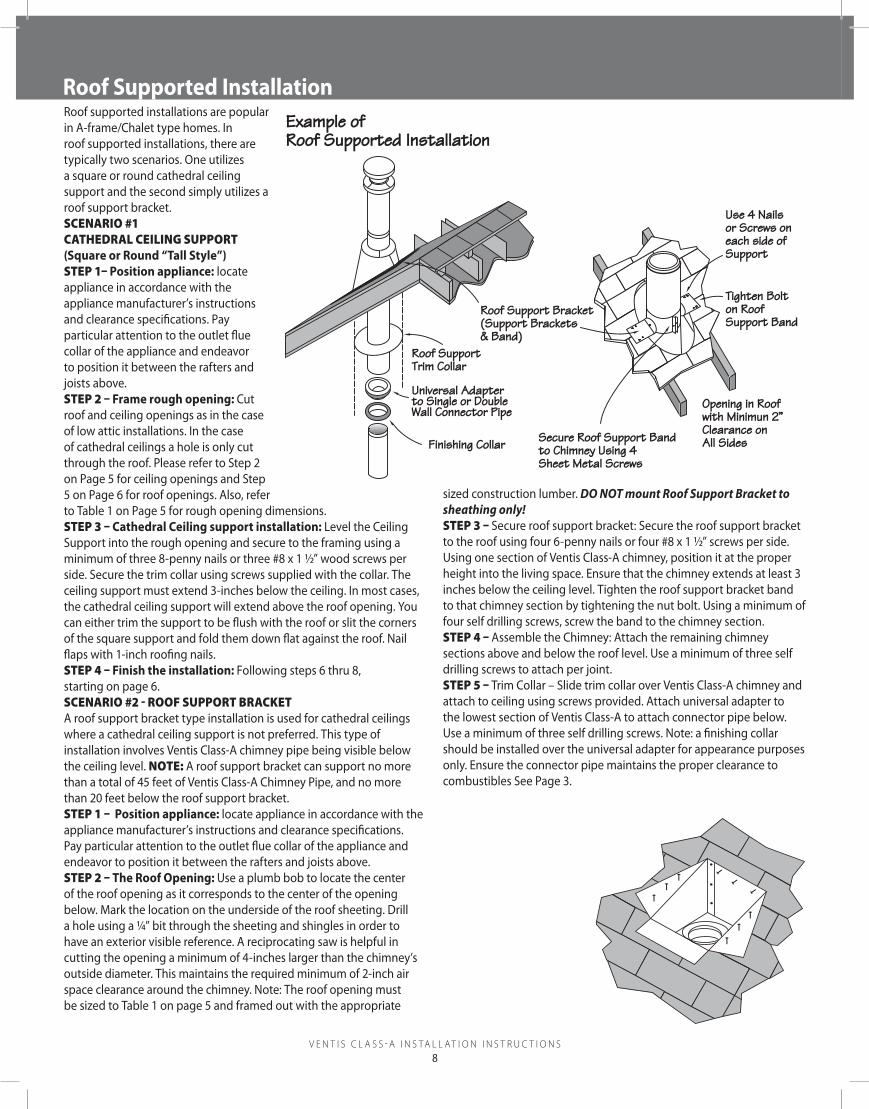
roof Supported InstallationRoof supported installations are popular in A-frame/Chalet type homes. In roof supported installations, there are typically two scenarios. One utilizes a square or round cathedral ceiling support and the second simply utilizes a roof support bracket.sCEnario #1CaTHEdral CEiling supporT (Square or round “tall Style”)sTEp 1– position appliance: locate appliance in accordance with the appliance manufacturer’s instructions and clearance specifications. Pay particular attention to the outlet flue collar of the appliance and endeavor to position it between the rafters and joists above.sTEp 2 – Frame rough opening: Cut roof and ceiling openings as in the case of low attic installations. In the case of cathedral ceilings a hole is only cut through the roof. Please refer to Step 2 on Page 5 for ceiling openings and Step5 on Page 6 for roof openings. Also, refer to Table 1 on Page 5 for rough opening dimensions.sTEp 3 – Cathedral Ceiling support installation: Level the Ceiling Support into the rough opening and secure to the framing using a minimum of three 8-penny nails or three #8 x 1 ½” wood screws per side. Secure the trim collar using screws supplied with the collar. The ceiling support must extend 3-inches below the ceiling. In most cases, the cathedral ceiling support will extend above the roof opening. You can either trim the support to be flush with the roof or slit the corners of the square support and fold them down flat against the roof. Nail flaps with 1-inch roofing nails.sTEp 4 – Finish the installation: Following steps 6 thru 8, starting on page 6.sCEnario #2 - roof supporT braCkETA roof support bracket type installation is used for cathedral ceilings where a cathedral ceiling support is not preferred. This type of installation involves Ventis Class-A chimney pipe being visible below the ceiling level. noTE: A roof support bracket can support no more than a total of 45 feet of Ventis Class-A Chimney Pipe, and no more than 20 feet below the roof support bracket.sTEp 1 – position appliance: locate appliance in accordance with the appliance manufacturer’s instructions and clearance specifications. Pay particular attention to the outlet flue collar of the appliance and endeavor to position it between the rafters and joists above.sTEp 2 – the roof opening: Use a plumb bob to locate the center of the roof opening as it corresponds to the center of the opening below. Mark the location on the underside of the roof sheeting. Drill a hole using a ¼” bit through the sheeting and shingles in order to have an exterior visible reference. A reciprocating saw is helpful in cutting the opening a minimum of 4-inches larger than the chimney’s outside diameter. This maintains the required minimum of 2-inch air space clearance around the chimney. Note: The roof opening must be sized to Table 1 on page 5 and framed out with the appropriate
sized construction lumber. DO NOT mount Roof Support Bracket to sheathing only!sTEp 3 – Secure roof support bracket: Secure the roof support bracket to the roof using four 6-penny nails or four #8 x 1 ½” screws per side. Using one section of Ventis Class-A chimney, position it at the proper height into the living space. Ensure that the chimney extends at least 3 inches below the ceiling level. Tighten the roof support bracket band to that chimney section by tightening the nut bolt. Using a minimum of four self drilling screws, screw the band to the chimney section.sTEp 4 – Assemble the Chimney: Attach the remaining chimney sections above and below the roof level. Use a minimum of three self drilling screws to attach per joint.sTEp 5 – Trim Collar – Slide trim collar over Ventis Class-A chimney and attach to ceiling using screws provided. Attach universal adapter to the lowest section of Ventis Class-A to attach connector pipe below. Use a minimum of three self drilling screws. Note: a finishing collar should be installed over the universal adapter for appearance purposes only. Ensure the connector pipe maintains the proper clearance to combustibles See Page 3.
Use 4 Nails or Screws on each side of Support
Tighten Bolt on Roof Support Band
Opening in Roofwith Minimun 2”Clearance on All Sides
Roof Support Bracket (Support Brackets & Band)
Secure Roof Support Bandto Chimney Using 4 Sheet Metal Screws
Roof SupportTrim Collar
Finishing Collar
Universal Adapterto Single or Double Wall Connector Pipe
Example of Roof Supported Installation
V e n t i s C l a s s - a i n s t a l l a t i o n i n s t r u C t i o n s9
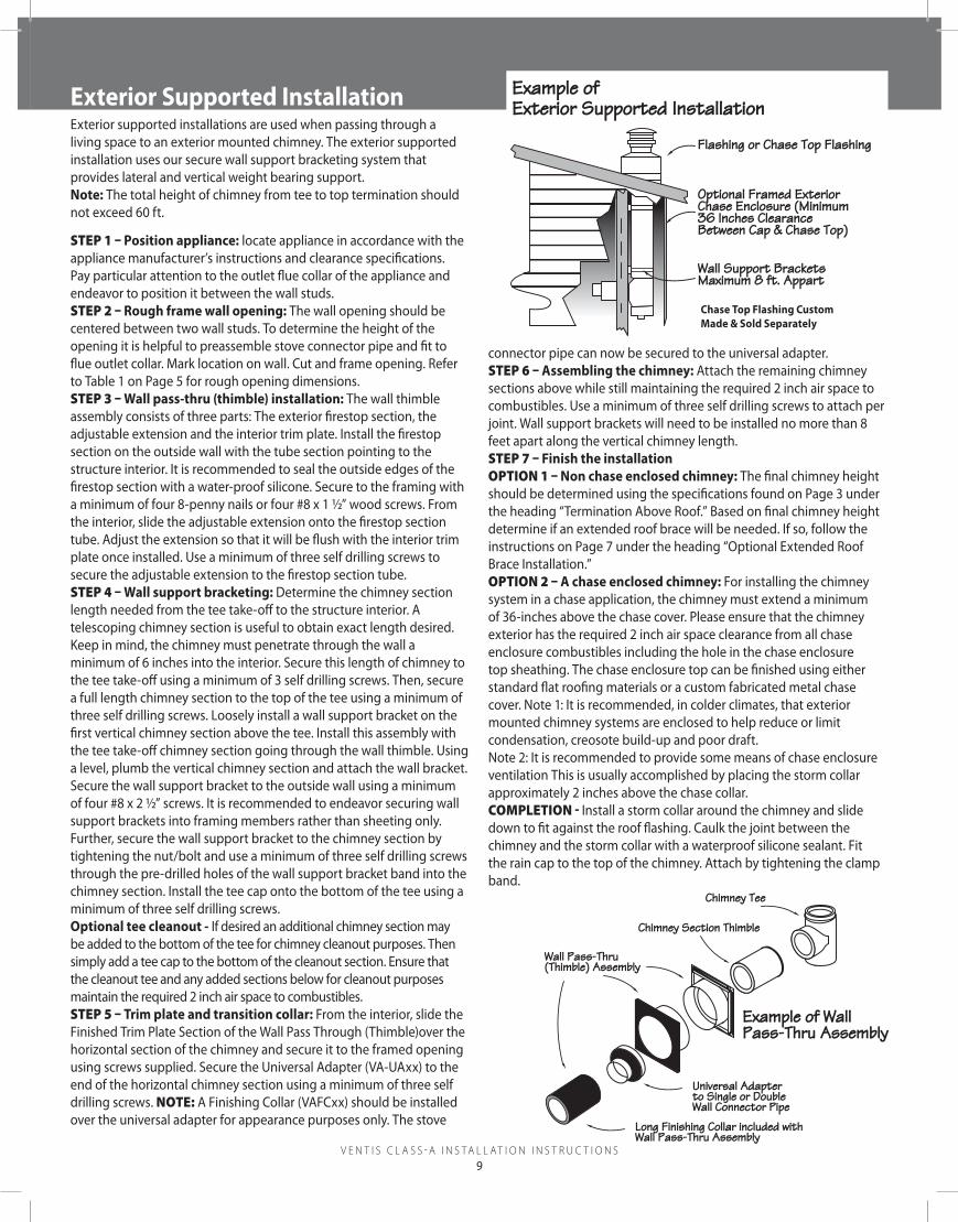
roof Supported InstallationExterior supported installations are used when passing through a living space to an exterior mounted chimney. The exterior supported installation uses our secure wall support bracketing system that provides lateral and vertical weight bearing support. note: The total height of chimney from tee to top termination should not exceed 60 ft.
sTEp 1 – position appliance: locate appliance in accordance with the appliance manufacturer’s instructions and clearance specifications. Pay particular attention to the outlet flue collar of the appliance and endeavor to position it between the wall studs. sTEp 2 – rough frame wall opening: The wall opening should be centered between two wall studs. To determine the height of the opening it is helpful to preassemble stove connector pipe and fit to flue outlet collar. Mark location on wall. Cut and frame opening. Refer to Table 1 on Page 5 for rough opening dimensions. sTEp 3 – wall pass-thru (thimble) installation: The wall thimble assembly consists of three parts: The exterior firestop section, the adjustable extension and the interior trim plate. Install the firestop section on the outside wall with the tube section pointing to the structure interior. It is recommended to seal the outside edges of the firestop section with a water-proof silicone. Secure to the framing with a minimum of four 8-penny nails or four #8 x 1 ½” wood screws. From the interior, slide the adjustable extension onto the firestop section tube. Adjust the extension so that it will be flush with the interior trim plate once installed. Use a minimum of three self drilling screws to secure the adjustable extension to the firestop section tube. sTEp 4 – wall support bracketing: Determine the chimney section length needed from the tee take-off to the structure interior. A telescoping chimney section is useful to obtain exact length desired. Keep in mind, the chimney must penetrate through the wall a minimum of 6 inches into the interior. Secure this length of chimney to the tee take-off using a minimum of 3 self drilling screws. Then, secure a full length chimney section to the top of the tee using a minimum of three self drilling screws. Loosely install a wall support bracket on the first vertical chimney section above the tee. Install this assembly with the tee take-off chimney section going through the wall thimble. Using a level, plumb the vertical chimney section and attach the wall bracket. Secure the wall support bracket to the outside wall using a minimum of four #8 x 2 ½” screws. It is recommended to endeavor securing wall support brackets into framing members rather than sheeting only. Further, secure the wall support bracket to the chimney section by tightening the nut/bolt and use a minimum of three self drilling screws through the pre-drilled holes of the wall support bracket band into the chimney section. Install the tee cap onto the bottom of the tee using a minimum of three self drilling screws. optional tee cleanout - If desired an additional chimney section may be added to the bottom of the tee for chimney cleanout purposes. Then simply add a tee cap to the bottom of the cleanout section. Ensure that the cleanout tee and any added sections below for cleanout purposes maintain the required 2 inch air space to combustibles. sTEp 5 – trim plate and transition collar: From the interior, slide the Finished Trim Plate Section of the Wall Pass Through (Thimble)over the horizontal section of the chimney and secure it to the framed opening using screws supplied. Secure the Universal Adapter (VA-UAxx) to the end of the horizontal chimney section using a minimum of three self drilling screws. noTE: A Finishing Collar (VAFCxx) should be installed over the universal adapter for appearance purposes only. The stove
connector pipe can now be secured to the universal adapter. sTEp 6 – Assembling the chimney: Attach the remaining chimney sections above while still maintaining the required 2 inch air space to combustibles. Use a minimum of three self drilling screws to attach per joint. Wall support brackets will need to be installed no more than 8 feet apart along the vertical chimney length. sTEp 7 – Finish the installationopTion 1 – non chase enclosed chimney: The final chimney height should be determined using the specifications found on Page 3 under the heading “Termination Above Roof.” Based on final chimney height determine if an extended roof brace will be needed. If so, follow the instructions on Page 7 under the heading “Optional Extended Roof Brace Installation.” opTion 2 – A chase enclosed chimney: For installing the chimney system in a chase application, the chimney must extend a minimum of 36-inches above the chase cover. Please ensure that the chimney exterior has the required 2 inch air space clearance from all chase enclosure combustibles including the hole in the chase enclosure top sheathing. The chase enclosure top can be finished using either standard flat roofing materials or a custom fabricated metal chase cover. Note 1: It is recommended, in colder climates, that exterior mounted chimney systems are enclosed to help reduce or limit condensation, creosote build-up and poor draft. Note 2: It is recommended to provide some means of chase enclosure ventilation This is usually accomplished by placing the storm collar approximately 2 inches above the chase collar. ComplETion - Install a storm collar around the chimney and slide down to fit against the roof flashing. Caulk the joint between the chimney and the storm collar with a waterproof silicone sealant. Fit the rain cap to the top of the chimney. Attach by tightening the clamp band.
Universal Adapterto Single or Double Wall Connector Pipe
Example of Wall Pass-Thru Assembly
Wall Pass-Thru (Thimble) Assembly
Chimney Section Thimble
Long Finishing Collar included withWall Pass-Thru Assembly
V e n t i s C l a s s - a i n s t a l l a t i o n i n s t r u C t i o n s10
masonry Chimney InstallationsTEp 1 – To properly size the chimney for a masonry fireplace, the cross sectional area of the chimney (ID – inner diameter) is to be a minimum of 1/12th of the area of the firebox opening.sTEp 2 – Install fireplace anchor plate. Seal the fireplace anchor plate to the masonry flue opening with high temperature adhesive/sealant. Further secure the fireplace anchor plate in each corner with four ¼” x 2” tapcon type masonry anchors. Always maintain a 1 inch air space clearance from the mounting plate to combustibles. Note: Make sure the mounting plate is level and anchored toa flat surface. Modify the masonry to obtain a flat level surface if neededsTEp 3 – Assemble the Chimney: Secure the first chimney section to the fireplace anchor plate with a minimum of three self drilling screws. Attach the remaining chimney sections above while still maintaining the required 2 inch air space between combustibles. Use a minimum of three d to be installed no more than 8 feet apart along the vertical chimney length. The final chimney height should be determined using the specifications found on Page 2 under the heading “Termination
Above Roof.” Be sure to enclose the chimney if it should pass through occupied areas.sTEp 4 – Completing the top termination: Please refer to Step 8 on page 7 for instructions to complete the top termination. If thechimney is within a chase enclosure, please refer to Page 9, Step 7, Option 2.
Only install the Ventis Class-A Chimney System with factory built, or zero clearance fireplaces, that approve its’ use. Be sure to read thoroughly and follow the fireplace manufacturer’s installa-tion instructions.sTEp 1 – Install fireplace anchor plate. Seal the fireplace anchor plate to the flue opening of the fireplace with high temperature adhesive/sealant if permitted by
the manufacturer. Secure the fireplace anchor plate in each corner with four ½” sheet metal screws. Always maintain a 1 inch air space clear-ance from the anchor plate to combustibles.
sTEp 2 – Assemble the Chimney: Secure the first chimney section to the fireplace anchor plate with a minimum of three self drilling screws. Attach the remaining chimney sections above while still maintaining the required 2 inch air space to combustibles. Use a minimum of three self drilling screws to attach per joint. wall support brackets will need to be installed no more than8 feet apart along the vertical chimney length. The final chimney height should be determined using the specifications found on Page 3 under the heading “Termination Above Roof.” Be sure to enclose the chimney if it should pass through occupied areas.sTEp 3 – Completing the top termination: Refer to Step 8 on page 7 for instructions to complete the top termination. If the chimney is within a chase enclosure, refer to Page 9, Step 7, Option 2.
Transition Plate
Anchor Plate
Chimney SectionSheet MetalScrews (4 Required)
Example ofFactory Built Fireplace Installation
Factory built (Zero Clearance) Fireplace Installation
Example ofMasonry Fireplace Installation
Anchor Plate
transition plate For Chimney restorationA transition plate is similar to an anchor plate, but is designed for transition from a single wall flue liner (such as Forever Flex, Rhino Rigid or Armor Flex to Ventis Class-A in a chimney restoration). Seal the transition plate to the masonry chimney opening with high temperature adhesive/sealant or mortar. Further secure the transition plate in each corner with four ¼” x 2” tapcon type masonry anchors. Always maintain a 1 inch air space clearance from the mounting plate to combustibles. Ensure the masonry chimney is a minimum of 10” above insulation and any other attic combustibles. Attach the remaining chimney sections above while still maintaining the required 2 inch air space to combustibles. Use a minimum of three self drilling screwsto at-tach per joint. Refer to page 6, step 5 for the roof opening and page 7, step 8 for top termination.
The chimney system must be installed and service by a qualifi ed chimney or venting professional. The criteria for the inspection and maintenance must be in conformance with local or state building codes, whichever has jurisdiction. It is recommended you use an inspection form and make notes that you can review with the homeowner.
warning for solid fuEl appliCaTions“Creosote and Soot-Formation and Need for Removal: When wood is burned slowly, it produces tar and other organic vapors, which combine with expelled moisture to form creosote. The creosote vapors condense in the relatively cool chimney fl ue of a slow-burning fi re. As a result, creosote residue accumulates on the fl ue lining. When ignited, this creosote makes an extremely hot fi re. The chimney should be inspected at least once every 2 months during the heating season to determine if a creosote or soot buildup has occurred. If creosote or soot has accumulated, it should be removed to reduce the risk of a chimney fi re.”
mainTEnanCE proCEdurEsIt is important that the chimney system be checked and cleaned annually. This is for the safety of the homeowner and necessary to meet the warranty requirements of Ventis Class-A. As noted above, in the case of solid fuel burning appliances, more frequent maintenance may be required, depending on use and the appliance manufacturer’s instructions. The entire system, from the connection at the appliance to the top of the chimney must be completely inspected and cleaned.
To clean the chimney lining system it is recommended to perform the following:1) Remove cap by either removing the 4 bolts on the cap lid or by loosening the clamp band.2) Select the proper sized chimney brush to clean the chimney. Be sure the brush head passes throughout the complete length of the liner, including the connectors, terminals and tees.3) In some instances, proper cleaning will require removing the appliance and disassembling the connector assembly tothoroughly inspect and clean parts that cannot be reached otherwise.4) Inspect and clean the chimney cap. Spark arrestors and other screens may be necessary or required in some areas, but may be susceptible to blockage from creosote or through freezing moisture in areas of low ambient temperature.5) Reinstall chimney cap6) Before the initial fi ring of the appliance, check the appliance’s operating instructions for initial fi ring precautions.
addiTional informaTion1) The Ventis Class-A chimney system is intended for use with heating appliances, burning home heating oil, natural or LP gas and solid fuels (pellet, wood, and coal). Use of experimental fuels is not permitted and voids the warranty.2) Use only components listed for use with the Venis Class-A Chimney System3) For solid-fuels, the chimney system is not to be sized less than that specifi ed in the appliance manufacturer’s instructions.
maintenance Instructions
Customer Name
Address
City State Zip
Phone
Installer Name
Company
Address
City State Zip
Phone
Date of Installation
Please register this information today. This will help us to provide you with the best warranty service. Choose from the following.
1. register online at www.olympiachimney.com2. Register by mail by filing out the information below and mailing to: Olympia Chimney Supply, Inc., 600 Sanders Street, Scranton, PA 18505
warranty registration Card
TypE of applianCE vEnTEd:
Wood Stove
Fireplace Insert
Fireplace
Gas Log
Coal Appliance (low sulfur only)
Water Heater
Gas Central Heating System
Oil Central Heating System
Other (specify)
limited Forever warranty tm
Ventis® Class-A All-Fuel Chimney pipe
VENTIS® Class-A All-Fuel Chimney Pipe is designed to vent residential heating oil, untreated wood, low sulphur coal and natural or LP gas.
limited warranty CoverageOlympia Chimney Supply, Inc. (Olympia) warrants to you (the “purchaser”) that for the period set forth below, the VENTIS® Class-A All-Fuel Chimney pipe and components when used according to the specifications set forth in the warranty & installation instructions; and, if properly installed, maintained and used shall be free from defects in material or manufacturer’s workmanship. This warranty provides for the replacement of any system components damaged in a chimney fire or that fail as a result of normal use on a residential fireplace, wood burning stove, furnace or boiler. It does not provide a cash surrender value or reimbursement for expenses associated with labor of any kind that is required in the removal or replacement of the VENTIS® system replaced under this warranty. This warranty does not cover normal wear and tear, damage caused to the structure by chimney fires, misuse of the chimney system or any components or parts not manufactured by Olympia. Following a chimney fire, the system must be inspected by an experienced chimney professional before resuming use of the heating appliance.
Coal warranty CoverageA chimney system connected to a low sulphur coal appliance that uses a 304L stainless steel inner wall is covered 100% for 10 years, then 50% for subsequent years as set forth in this warranty. A chimney system connected to a low sulphur coal appliance that uses a 316L stainless steel inner wall is covered 100% for the life of the system as set forth in this warranty. All terms in the above “Limited Warranty Coverage” also apply.
warranty periodThe benefits of this warranty shall apply to you (the “purchaser”) Forever with no time limit, provided that you continue to own the home where the Ventis® Class-A All Fuel Chimney system is installed. In all events, even if you sell your home, Olympia will honor the warranty Forever with no time limit, which allows that new owner to benefit from the Ventis® Class-A All-Fuel Chimney system installation in your home.
warranty Conditions and limitations You may register your VENTIS® Class-A All-Fuel Chimney System online at www.olympiachimney.com or by mailing your registration card to the address specified on the card within 60 days of having your system installed. The Ventis® warranty is subject to the following conditions: 1) installation of the pipe and components must be in accordance with the manufacturer’s written instructions; 2) the pipe is designed to operate at a continuous temperature of 650 degree Celsius (1,200 degree farenheit) or less; 3) this warranty only covers the use of low sulphur coal, all other types of coal are not covered under this warranty; 4) corn, driftwood, wood or wood pellets containing salt, preservative treated lumber, plastic, experimental fuels and household trash must not be burned in the appliance; 5) this warranty does not cover any products that have been moved from their original installation site; 6) the Ventis® chimney system must be cleaned and inspected on an annual basis by an experienced chimney professional commencing from the date of purchase. Receipts verifying that the annual maintenance was performed must be retained.
Claim process and limitations of liabilityYou may make a claim under this warranty by giving notice to your chimney professional and having your chimney professional provide information about the claim to Olympia. Upon approval of your claim, Olympia shall provide new Ventis® pipe and components to you as your exclusive remedy. Olympia does not assume any liability or responsibility for faulty installation of the pipe or components, or for defective materials not supplied as part of the Ventis® chimney system.
Neither Olympia nor the installer of the Ventis® chimney system shall be liable for any removal or installation charges or for any special, incidental, or consequential damages in any way related to the Ventis® pipe. This warranty gives you specific legal rights, and you may also have other rights, which vary from state to state. Some states do not allow the exclusion or limitations of incidental or consequential damages, so the above limitations or exclusions may not apply to you.