77-3047KP TOOLS NEEDED: NOTE: FAILURE TO FOLLOW INSTALLATION INSTRUCTIONS AND NOT USING THE PROVIDED HARDWARE MAY DAMAGE THE INTAKE TUBE, THROTTLE BODY AND ENGINE. NOTE: This kit was not designed to fit vehicles with a body lift. 1. Turn off the ignition and disconnect the negative battery cable. NOTE: Disconnecting the negative battery cable erases pre-programmed electronic memories. Write down all memory settings before disconnecting the negative battery cable. Some radios will require an anti-theft code to be entered after the battery is reconnected. The anti-theft code is typically supplied with your owner’s manual. In the event your vehicles’ anti-theft code cannot be recovered, contact an authorized dealership to obtain your vehicles anti-theft code. TO START: CHEVROLET / GMC 2004-05 SILVERADO 2500HD, 3500 2004-05 SIERRA 2500HD, 3500 V8-6.6L Turbo Diesel (LLY) Description Qty. Part # Description Qty. Part # Description Qty. Part # A hose clamp #56 2 08620 B silicone hose 1 08456 C intake tube 1 27414 D bolt; m4-.7, b/h/a 2 07726 E bracket 1 010080 F washer 1/4"id x 5/8" od, flat 5 08275 G washer 1/4"split lock 1 08198 H bolt; m6-1.00 x 16mm, hex head 3 07703 I heat shield 1 07457 J edge trim 50" 1 102481 K nut; m6 nylock 2 07553 L bracket 1 070025 M hose clamp #60 1 08624 N air filter 1 RC-5112 O torx wrench t-20 1 69801 PARTS LIST: Flat Blade Screwdriver Ratchet Extension 10mm Socket 14mm Socket 2.5mm Allen 9/64” allen 10mm Wrench O 2. Depress the locking tab on the mass air sensor electrical connector, and then disconnect the electrical connection. 3. Loosen the hose clamp, which secures the intake tube to the intake manifold, and then disconnect the intake tube from the intake manifold. 4. Lift up on the air box assembly to release from the mounting grommets, and then remove the air box and intake tube assembly from the vehicle. NOTE: K&N Engineering, Inc., recommends that customers do not discard factory air intake. 5. Install the silicone hose (08456) onto the intake manifold and secure with the provided hose clamps. 6. Remove the lower front engine processor mounting bolt shown. 7. Using the factory bolt removed in step #6, install the tube mounting bracket to the engine processor as shown. 8. Apply the provided trim seal to the heat shield assembly as show. Trim if necessary. 9. Install bracket onto heat shield as shown. Do not tighten completely.
Transcript
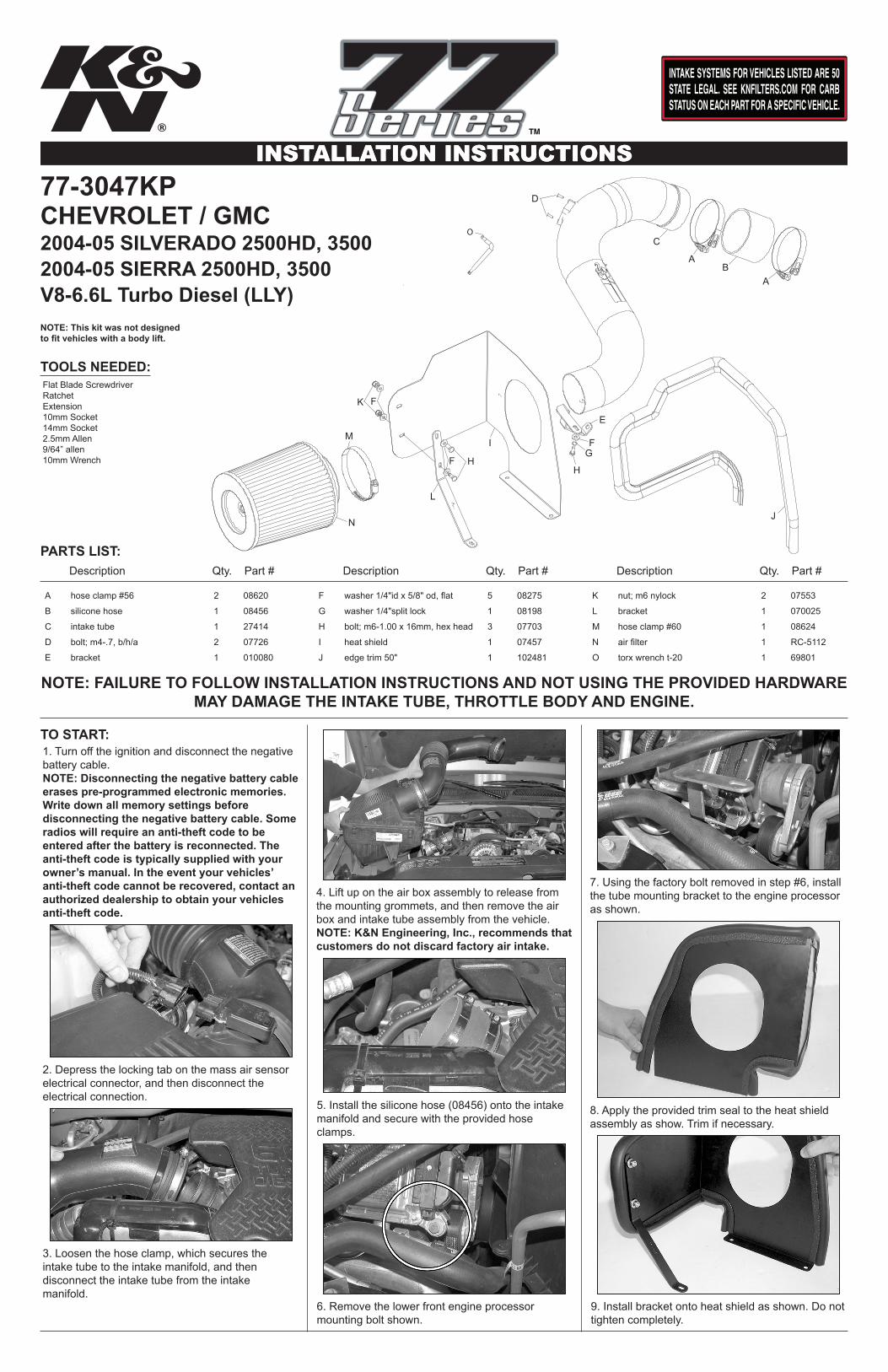
77-3047KP
TOOLS NEEDED:
NOTE: FAILURE TO FOLLOW INSTALLATION INSTRUCTIONS AND NOT USING THE PROVIDED HARDWARE MAY DAMAGE THE INTAKE TUBE, THROTTLE BODY AND ENGINE.
NOTE: This kit was not designed to fit vehicles with a body lift.
1. Turn off the ignition and disconnect the negative battery cable.NOTE: Disconnecting the negative battery cable erases pre-programmed electronic memories. Write down all memory settings before disconnecting the negative battery cable. Some radios will require an anti-theft code to be entered after the battery is reconnected. The anti-theft code is typically supplied with your owner’s manual. In the event your vehicles’ anti-theft code cannot be recovered, contact an authorized dealership to obtain your vehicles anti-theft code.
TO START:
CHEVROLET / GMC2004-05 SILVERADO 2500HD, 35002004-05 SIERRA 2500HD, 3500V8-6.6L Turbo Diesel (LLY)
Description Qty. Part # Description Qty. Part # Description Qty. Part #
2. Depress the locking tab on the mass air sensor electrical connector, and then disconnect the electrical connection.
3. Loosen the hose clamp, which secures the intake tube to the intake manifold, and then disconnect the intake tube from the intake manifold.
4. Lift up on the air box assembly to release from the mounting grommets, and then remove the air box and intake tube assembly from the vehicle.NOTE: K&N Engineering, Inc., recommends that customers do not discard factory air intake.
5. Install the silicone hose (08456) onto the intake manifold and secure with the provided hose clamps.
6. Remove the lower front engine processor mounting bolt shown.
7. Using the factory bolt removed in step #6, install the tube mounting bracket to the engine processor as shown.
8. Apply the provided trim seal to the heat shield assembly as show. Trim if necessary.
9. Install bracket onto heat shield as shown. Do not tighten completely.
INSTALLATION INSTRUCTIONSContinued
ROAD TESTING:
23. It will be necessary for all K&N® high flow intake systems to be checked periodically for realignment, clearance and tightening of all connections. Failure to follow the above instructions or proper maintenance may void warranty.
21. Reconnect the vehicle’s negative battery cable. Double check to make sure everything is tight and properly positioned before starting the vehicle.
* FREE K&N® decal To register your warranty, please see us online at knfilters.com/register. FREE K&N® decal *• 1455 CITRUS ST., P.O. BOX 1329, RIVERSIDE, CA., U.S.A. 92502 • TECH SERVICE 800-858-3333 • FAX 951-826-4001
22. The C.A.R.B. exemption sticker, (attached), must be visible under the hood so that an emissions inspector can see it when the vehicle is required to be tested for emissions. California requires testing every two years, other states may vary.
1. Start the engine with the transmission in neutral or park, and the parking brake engaged. Listen for air leaks or odd noises. For air leaks secure hoses and connections. For odd noises, find cause and repair before proceeding. This kit will function identically to the factory system except for being louder and much more responsive.
2. Test drive the vehicle. Listen for odd noises or rattles and fix as necessary.
3. If road test is fine, you can now enjoy the added power and performance from your kit.
4. K&N Engineering, Inc., requires cleaning the intake system’s air filter element every 100,000miles. When used in dusty or off-road environments, our filters will require cleaning moreoften. We recommend that you visually inspect your filter once every 25,000 miles to determine if the screen is still visible. When the screen is no longer visible some place on the filter element, it is time to clean it. To clean and re-oil, purchase our filter Recharger® service kit, part number 99-5050 or 99-5000 and follow the easy instructions.
17562G11/26/14
10. Remove the three bolts from the stock airbox mounting tray.
11. Mount the heat shield onto the airbox mounting tray and secure with the three bolts removed in step 10.
12. Using the “TORX” T20 wrench provided, loosen and remove the two-torx screw that retain the mass air sensor, and then remove the sensor.
13. Remove the restriction gauge and grommet from the stock air box as shown.
14. Install the mass air sensor into the K&N® intake tube and secure with the provided hardware as shown.
15. Install the K&N® intake tube into the silicone hose at the intake inlet, then align the tube to the mounting bracket installed in step #7 and secure with the provided hardware.
16. Adjust heat shield and bracket for necessary clearance, then tighten all hardware completely.
17. Install grommet onto filter as shown.
18. Install filter restriction gauge onto Air filter as shown.
19. Install the K&N® Air filter onto intake tube as shown then tighten completely.
20. Reconnect the mass air sensor electrical connection as shown.