22
Image size: 7,94 cm x 25,4 cm Workshop on Eurocode 4-2 Composite Bridges Swedish experiences from Eurocode Robert Hällmark Bridge Designer, Ramböll Sverige AB

8/13/2019 7_Swedish experience from EC4-2_Robert_Hällmark
http://slidepdf.com/reader/full/7swedish-experience-from-ec4-2roberthaellmark 1/22
Image size: 7,94 cm x 25,4 cm
Workshop on Eurocode 4-2Composite Bridges
Swedish experiences from Eurocode
Robert Hällmark
Bridge Designer, Ramböll Sverige AB
8/13/2019 7_Swedish experience from EC4-2_Robert_Hällmark
http://slidepdf.com/reader/full/7swedish-experience-from-ec4-2roberthaellmark 2/22
Table of contents
• Eurocode from a Swedish bridge designers point of view
⇒ Eurocode vs. the old Swedish Bridge Code
A more national approach than previous speakers
• Problems using the codes
• Improvement proposals
8/13/2019 7_Swedish experience from EC4-2_Robert_Hällmark
http://slidepdf.com/reader/full/7swedish-experience-from-ec4-2roberthaellmark 3/22
Reference bridges
• Three bridges designed according to Eurocode will be the reference
objects for this presentation
- One single span bridge I-girders
- One multi span bridge I-girders
- One multi span bridge Box-girder

8/13/2019 7_Swedish experience from EC4-2_Robert_Hällmark
http://slidepdf.com/reader/full/7swedish-experience-from-ec4-2roberthaellmark 4/22
Bridge 1: Skulnäs – Bridge over E4
• Single span bridge in northern Sweden
• Span length 32 m, two I-girders.
• Steel girder height 1,5 m.
• Local road that crosses a highway – AADT 50-200
8/13/2019 7_Swedish experience from EC4-2_Robert_Hällmark
http://slidepdf.com/reader/full/7swedish-experience-from-ec4-2roberthaellmark 5/22
Bridge 1: Skulnäs – Bridge over E4
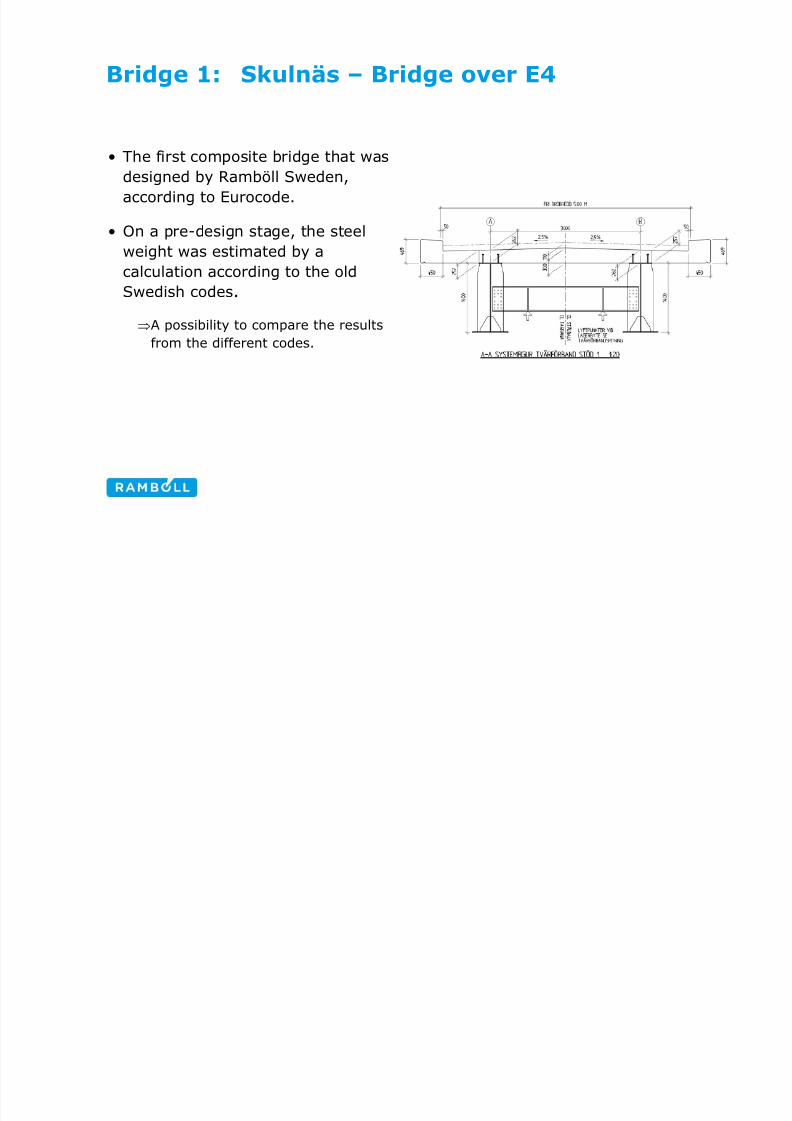
• The first composite bridge that was
designed by Ramböll Sweden,
according to Eurocode.
• On a pre-design stage, the steel
weight was estimated by a
calculation according to the old
Swedish codes.
⇒A possibility to compare the results
from the different codes.

8/13/2019 7_Swedish experience from EC4-2_Robert_Hällmark
http://slidepdf.com/reader/full/7swedish-experience-from-ec4-2roberthaellmark 6/22
Bridge 2: Forsjö-bridge, Katrineholm RV55
• Five span bridge, two I-girders
• Span length 45-58 m
• Steel girder height of 2,5 m
• AADT ~5000-6000

8/13/2019 7_Swedish experience from EC4-2_Robert_Hällmark
http://slidepdf.com/reader/full/7swedish-experience-from-ec4-2roberthaellmark 7/22
Bridge 3: NN (under tender evaluation)
• 2 cable stayed main-spans
• 2 approach bridges > 500 m, composite
cross-section
• Span length 64-90 m
• Box-girder height > 4,0 m

8/13/2019 7_Swedish experience from EC4-2_Robert_Hällmark
http://slidepdf.com/reader/full/7swedish-experience-from-ec4-2roberthaellmark 8/22
Main objectives in this presentation
• Global analysis
• Design in ULS
• Fatigue design
• Design in SLS
8/13/2019 7_Swedish experience from EC4-2_Robert_Hällmark
http://slidepdf.com/reader/full/7swedish-experience-from-ec4-2roberthaellmark 9/22
-20
-15
-10
-5
0
5
10
15
20
0 50 100 150 200 250x [m] M [ M N m ]
B ro 20 04 E ur oc od eEC Sw.code
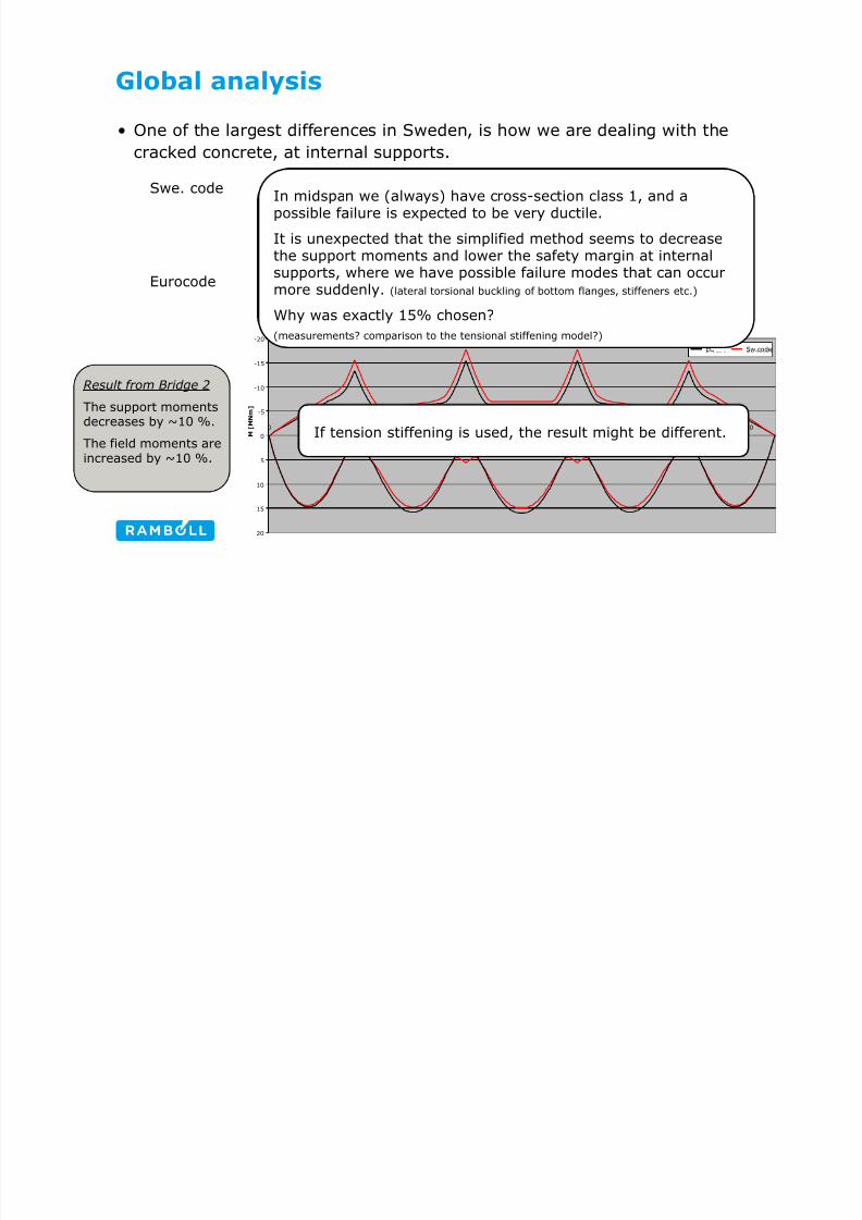
Global analysis
• One of the largest differences in Sweden, is how we are dealing with the
cracked concrete, at internal supports.
Swe. code ⇒ ~20-25% of the span length on both side of an
internal support is treated as cracked-concrete. Thecracked concrete is modelled with a 60% stiffness
compared to uncracked concrete.
Eurocode ⇒ The “15%-method” has been used so far, due to its
simplicity (only one global analysis is necessary).
Result from Bridge 2
The support moments
decreases by ~10 %.The field moments areincreased by ~10 %.
In midspan we (always) have cross-section class 1, and a
possible failure is expected to be very ductile.
It is unexpected that the simplified method seems to decreasethe support moments and lower the safety margin at internalsupports, where we have possible failure modes that can occurmore suddenly. (lateral torsional buckling of bottom flanges, stiffeners etc.)
Why was exactly 15% chosen?(measurements? comparison to the tensional stiffening model?)
If tension stiffening is used, the result might be different.
8/13/2019 7_Swedish experience from EC4-2_Robert_Hällmark
http://slidepdf.com/reader/full/7swedish-experience-from-ec4-2roberthaellmark 10/22
Global analysis
• Another difference is how we are dealing with concrete of varying age.
• Previously, as soon as composite action is achieved, the concrete has been given its
long term stiffness (one third of the short term stiffness).
-This stiffness has been used for all long term loading (concrete dead load, shrinkage, non-
structural bridge equipments etc.)
• Today, the bridge designer must estimate the construction procedure on an early
stage, since the concrete long term stiffness is treated as time dependent.
-The construction procedure and time schedule is often not known on an early stage. Therefore
the bridge designer has to estimate how long time it takes to cast each segment.
-For concrete dead loads, one mean value of the concrete age is used to model the concrete stiffness.
A small sensitivity analysis gives ⇒ A bad guess will not effect the design of thebridge significantly.
8/13/2019 7_Swedish experience from EC4-2_Robert_Hällmark
http://slidepdf.com/reader/full/7swedish-experience-from-ec4-2roberthaellmark 11/22
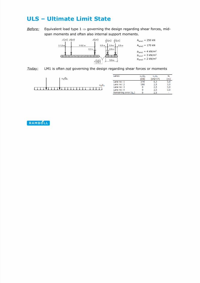
ULS – Ultimate Limit State
Before: Equivalent load type 1 ⇒ governing the design regarding shear forces, mid-
span moments and often also internal support moments.
Today: LM1 is often not governing the design regarding shear forces or moments
Alane1 = 250 kN
Alane2 = 170 kN
plane1 = 4 kN/m2
plane2 = 3 kN/m2
plane3 = 2 kN/m2
8/13/2019 7_Swedish experience from EC4-2_Robert_Hällmark
http://slidepdf.com/reader/full/7swedish-experience-from-ec4-2roberthaellmark 12/22
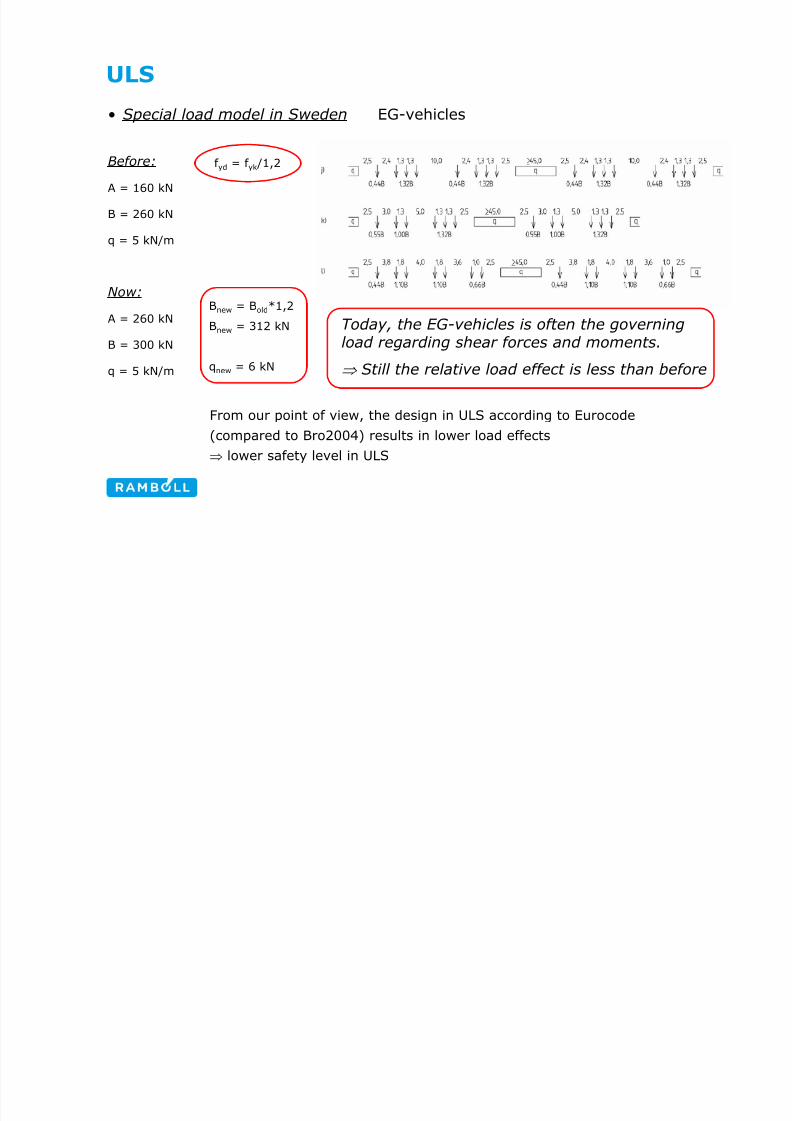
ULS
• Special load model in Sweden EG-vehicles
Before:
A = 160 kN
B = 260 kN
q = 5 kN/m
Now:
A = 260 kN
B = 300 kN
q = 5 kN/m
From our point of view, the design in ULS according to Eurocode
(compared to Bro2004) results in lower load effects
⇒ lower safety level in ULS
f yd = f yk /1,2
Bnew = Bold*1,2
Bnew = 312 kN
qnew = 6 kN
Today, the EG-vehicles is often the governingload regarding shear forces and moments.
⇒ Still the relative load effect is less than before
8/13/2019 7_Swedish experience from EC4-2_Robert_Hällmark
http://slidepdf.com/reader/full/7swedish-experience-from-ec4-2roberthaellmark 13/22
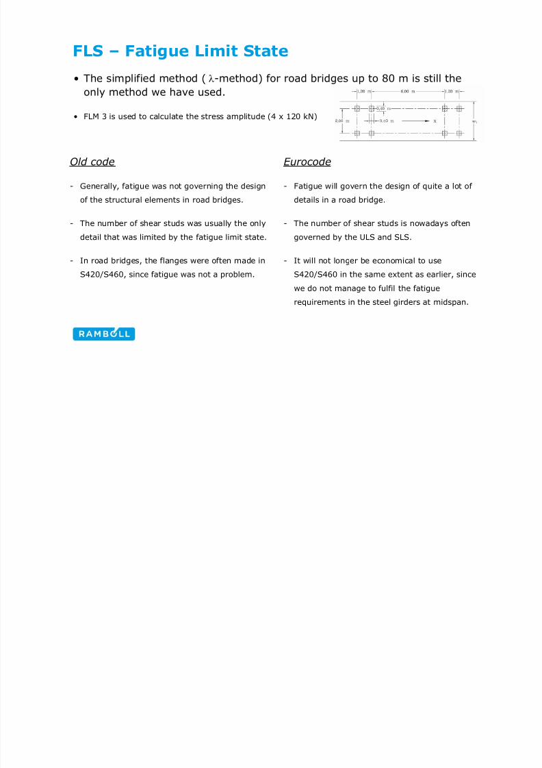
FLS – Fatigue Limit State
• The simplified method ( λ-method) for road bridges up to 80 m is still the
only method we have used.
• FLM 3 is used to calculate the stress amplitude (4 x 120 kN)
Old code
- Generally, fatigue was not governing the design
of the structural elements in road bridges.
- The number of shear studs was usually the only
detail that was limited by the fatigue limit state.
- In road bridges, the flanges were often made in
S420/S460, since fatigue was not a problem.
Eurocode
- Fatigue will govern the design of quite a lot of
details in a road bridge.
- The number of shear studs is nowadays often
governed by the ULS and SLS.
- It will not longer be economical to use
S420/S460 in the same extent as earlier, since
we do not manage to fulfil the fatigue
requirements in the steel girders at midspan.
8/13/2019 7_Swedish experience from EC4-2_Robert_Hällmark
http://slidepdf.com/reader/full/7swedish-experience-from-ec4-2roberthaellmark 14/22
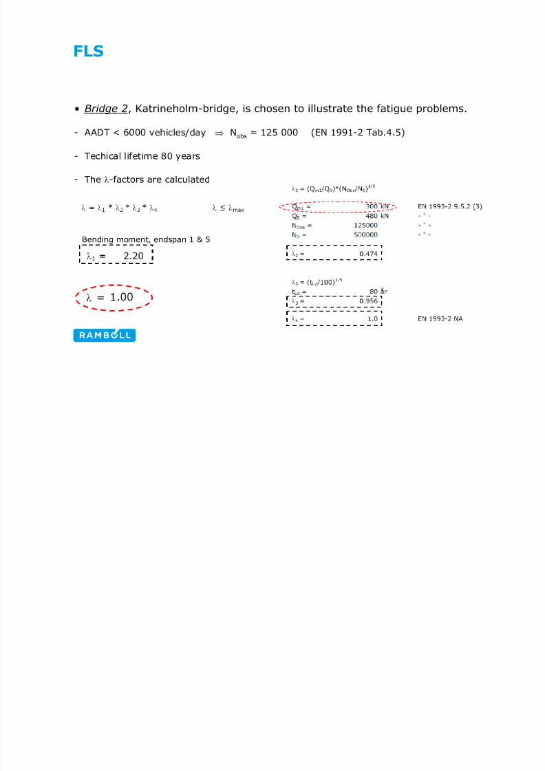
FLS
• Bridge 2, Katrineholm-bridge, is chosen to illustrate the fatigue problems.
- AADT < 6000 vehicles/day⇒
Nobs = 125 000 (EN 1991-2 Tab.4.5)
- Techical lifetime 80 years
- The λ-factors are calculated
Bending moment, endspan 1 & 5
8/13/2019 7_Swedish experience from EC4-2_Robert_Hällmark
http://slidepdf.com/reader/full/7swedish-experience-from-ec4-2roberthaellmark 15/22
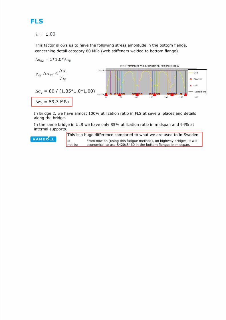
FLS
This factor allows us to have the following stress amplitude in the bottom flange,
concerning detail category 80 MPa (web stiffeners welded to bottom flange).
Δσp = 80 / (1,35*1,0*1,00)
Δσp = 59,3 MPa
In Bridge 2, we have almost 100% utilization ratio in FLS at several places and detailsalong the bridge.
In the same bridge in ULS we have only 85% utilization ratio in midspan and 94% atinternal supports.
This is a huge difference compared to what we are used to in Sweden.
⇒ From now on (using this fatigue method), on highway bridges, it willnot be economical to use S420/S460 in the bottom flanges in midspan.
8/13/2019 7_Swedish experience from EC4-2_Robert_Hällmark
http://slidepdf.com/reader/full/7swedish-experience-from-ec4-2roberthaellmark 16/22
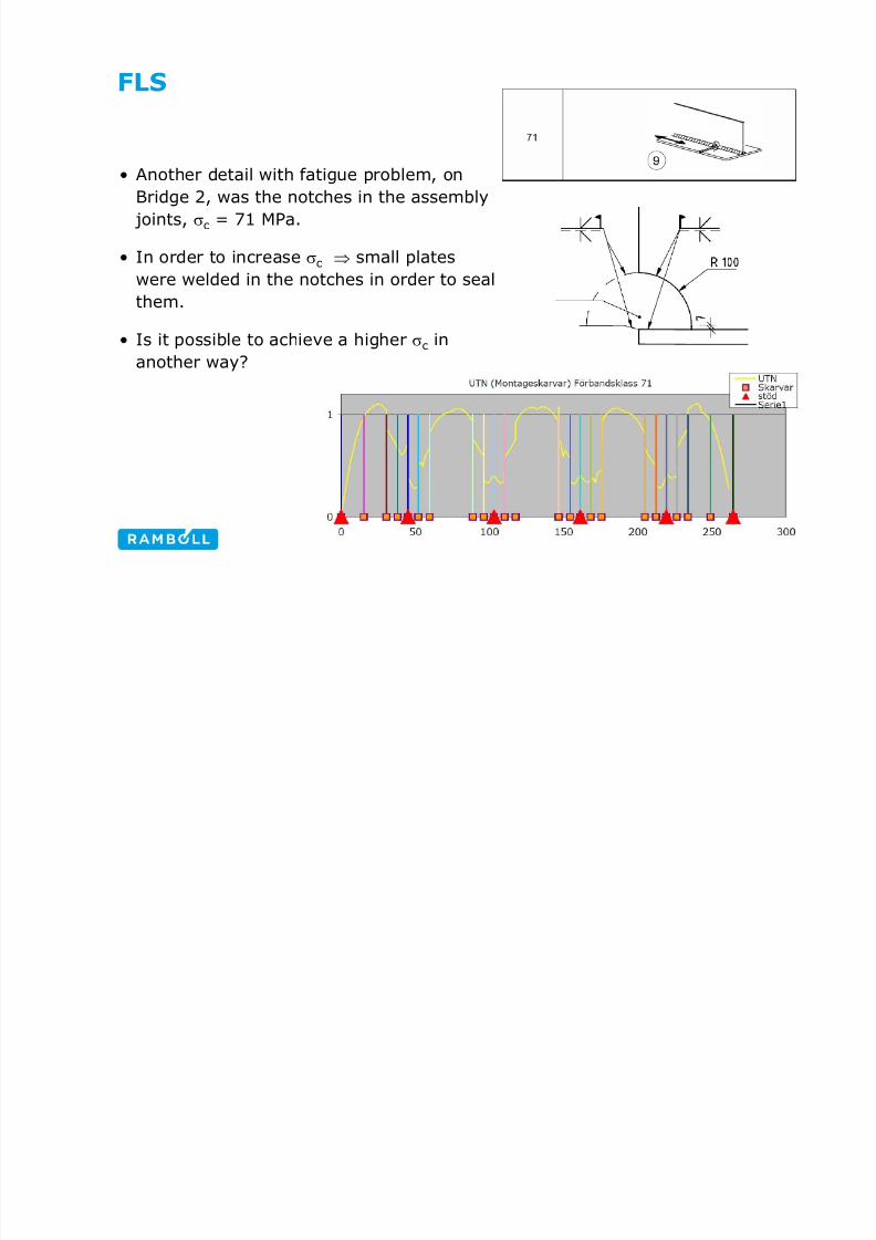
FLS
• Another detail with fatigue problem, on
Bridge 2, was the notches in the assembly
joints, σc = 71 MPa.
• In order to increase σc ⇒ small plates
were welded in the notches in order to seal
them.
• Is it possible to achieve a higher σc in
another way?

8/13/2019 7_Swedish experience from EC4-2_Robert_Hällmark
http://slidepdf.com/reader/full/7swedish-experience-from-ec4-2roberthaellmark 17/22
FLS
• If Bridge 2 would have an AADT > 10 000 ⇒ Nobs = 500 000 heavy
vehicles/year
- due to fatigue the total amount of steel is increased with several percentage.
- larger bottom flanges would be needed in the midspan (S460 ⇒ S355)
- the utilization ratio in ULS, would be far below 90% along the whole bridge.
• Bridge 1 have an AADT < 200 ⇒ Nobs = 50 000 heavy vehicles/year
- still this bridge has a utilisation ratio that is higher in FLS than in ULS
⇒ FLS seems to be governing the design of the midspan in all composite bridges, no
matter how few cars that crosses the bridge.

8/13/2019 7_Swedish experience from EC4-2_Robert_Hällmark
http://slidepdf.com/reader/full/7swedish-experience-from-ec4-2roberthaellmark 18/22
SLS – Serviceability Limit State
• SLS is mainly used to check the allowed deflection and breathing (in the
design of the steel girders)
- Breathing Previously, breathing has quite often been governing the web thickness in
the area where the bending moment are shifting from positive to
negative. (concrete shrinkage ⇒ compression over the whole web height)
Eurocode allows us to use extremely slender web plates without getting
problems with breathing.
For a road bridge with a span of 50 m, and a web height of 2,0 m, the
web plate can be as thin as 9 mm without problems with breathing.
⇒ Web breathing will never be a problem in Swedish bridges
according to this formula
8/13/2019 7_Swedish experience from EC4-2_Robert_Hällmark
http://slidepdf.com/reader/full/7swedish-experience-from-ec4-2roberthaellmark 19/22
Conclusions and discussion
• It seems as the safety level in ULS has been lowered.
• At the same time the safety level in FLS has been raised.
• Is this reflecting the reality?
- Fatigue failure seems to occur in the details that are not checked in the design
stage, and often due to other stresses than the nominal stresses in the girders.
- Do we have problems today with fatigue in composite road bridges? (in the details
that we are checking for fatigue)
- Is the national value Qm1 = 300 kN reasonable?
- UK Qm1 = 260 kN
- Other countries?

8/13/2019 7_Swedish experience from EC4-2_Robert_Hällmark
http://slidepdf.com/reader/full/7swedish-experience-from-ec4-2roberthaellmark 20/22
Problems using Eurocode
• Not one code ⇒ several codes, regulations, national constitutions
- hard to find what you are looking for
- a lot of references followed by another reference.
- a huge amount of paper to handle
• Lack of knowledge
- both among the bridge designers and the bridge owners
• In a lot of formulas it is hard to understand the background to all factors/parameters
- the simplified fatigue calculation model is one example
- it is hard to get a genuine feeling, how the formulas is reflecting the reality

8/13/2019 7_Swedish experience from EC4-2_Robert_Hällmark
http://slidepdf.com/reader/full/7swedish-experience-from-ec4-2roberthaellmark 21/22
Improvement/Research proposals
• In the design of Bridge 3 we have struggled a lot with
patch loading.
- the contractor would like to launch the steel-girders together
with the prefabricated concrete deck elements (except in the
cantilevering part)
- we have suggested to use two different plate thickness
in the same web
- the lowest 1,3 m will have a permanent thickness of 28 mm
- the upper 3,2 m will have a varying thickness (from plate to plate) between 15 - 28 mm
- since some of the Nordic steel producers have a limitation of their plate width to~3,2 m. It might be economic to use different web-thickness when a longitudinal
butt weld is already necessary.
- it would be nice with some guidelines how to deal with varying web thickness
Maybe this is a possible research topic!

8/13/2019 7_Swedish experience from EC4-2_Robert_Hällmark
http://slidepdf.com/reader/full/7swedish-experience-from-ec4-2roberthaellmark 22/22
THANK YOU
Questions?


