Application for the extension of I/Os on s 7SJ80 and 7SK80 via SICAM I/O-Unit 7XV5673 7XV5673_APP_IO-UNIT_7SX80_A2_EN.DOCX Page 1 of 13 Thomas Klotz EM EA PRO LM1 May 08, 2015 In this document the extension of binary inputs and outputs with up to two SICAM I/O-Units on the Ethernet service port A of 7SJ80/7SK80 is described. The SICAM I/O-Unit 7XV5673 has 6 binary inputs and 6 binary outputs. A 7SJ80 or a 7SK80 can be combined with up to two SICAM I/O-Units. For this the 7SJ80/7SK80 has to be equipped with the Ethernet service interface Port A (not IEC61850). Hence a 7SJ80/7SK80 can be extended by up to 12 binary inputs and up to 12 binary outputs. All settings on the SICAM I/O-Unit can be done through a Web-browser (e.g. Internet Explorer). Note: This application guide is only intended as additional user information and it is a prerequisite that the user has knowledge of the general operation and usage of the device and its basic functions as described in the device manual. Application: Get up to 12 additional BI and 12 additional BO on 7SJ80/7SK80 IP-Address 192.168.10.200 Subnet Mask 255.255.255.0 IP-Address 192.168.10.3 Subnet Mask 255.255.255.0 PC or Notebook to configure the I/O Units and the SIPROTEC Device SIPROTEC Compact with Ethernet-Port A 1 2 3 4 5 6 7 8 9 10 11 12 1 2 3 4 5 6 7 8 9 10 11 P N H N / - L / + 12 SIEMENS J 6 BI 6 BO 1 2 3 4 5 6 7 8 9 10 11 12 1 2 3 4 5 6 7 8 9 10 11 P N H N / - L / + 12 SIEMENS J 6 BI 6 BO SIEMENS RUN ERROR L1: 0A 12: 0.0kV Esc Enter 7SJ8031-5EB00-1HE0 SIEMENS L2: 0A 12: 0.0kV L3: 0A 12: 0.0kV E : 0A 12: 0.0kV EE: f : Anregung L1 Anregung L2 Anregung L3 Anregung E Aus L1 Aus L2 Aus L3 Double shielded Ethernet CAT 5 patch cable Y-Adapter for internal Switch 7SJ80x DIGSI 4 Browser I/O-Unit 1 7XV5673-0JJ00-1AA1 IP-Address 192.168.10.55 Subnet Mask 255.255.255.0 Port No. 51000 IP-Address 192.168.10.56 Subnet Mask 255.255.255.0 Port No. 51001 I/O-Unit 2 7XV5673-0JJ00-1AA1 To get up to 6 additional binary inputs and 6 binary outputs one SICAM I/O-Unit 7XV5673-0JJ00-1AA1 is connected via a double screened CAT5 patch cable (1:1 or crossed over) directly to the protection device (e.g. 7SJ80x / Port A). To get up to 12 additional binary inputs and 12 binary outputs two SICAM I/O-Units 7XV5673 and an additional Y-Ethernet cable (7KE6000-8GD00-0BA2) are needed. The protection device is set using DIGSI 4 running on a Notebook via the USB-front interface. The SICAM I/O-Unit 7XV5673 is set through a Web Browser running on the Notebook via the Ethernet interface. Tip: If during commissioning a common switch is temporarily inserted using three or four patch cables, the protection device can be set from a PC using DIGSI 4 in parallel with the I/O-Unit.
Transcript
Application for the extension of I/Os on s
7SJ80 and 7SK80 via SICAM I/O-Unit 7XV5673
7XV5673_APP_IO-UNIT_7SX80_A2_EN.DOCX Page 1 of 13 Thomas Klotz EM EA PRO LM1 May 08, 2015
In this document the extension of binary inputs and outputs with up to two SICAM I/O-Units on the Ethernet service port A of 7SJ80/7SK80 is described.
The SICAM I/O-Unit 7XV5673 has 6 binary inputs and 6 binary outputs. A 7SJ80 or a 7SK80 can be combined with up to two SICAM I/O-Units. For this the 7SJ80/7SK80 has to be equipped with the Ethernet service interface Port A (not IEC61850). Hence a 7SJ80/7SK80 can be extended by up to 12 binary inputs and up to 12 binary outputs. All settings on the SICAM I/O-Unit can be done through a Web-browser (e.g. Internet Explorer). Note: This application guide is only intended as additional user information and it is a prerequisite that the user has knowledge of the general operation and usage of the device and its basic functions as described in the device manual.
Application: Get up to 12 additional BI and 12 additional BO on 7SJ80/7SK80
To get up to 6 additional binary inputs and 6 binary outputs one SICAM I/O-Unit 7XV5673-0JJ00-1AA1 is connected via a double screened CAT5 patch cable (1:1 or crossed over) directly to the protection device (e.g. 7SJ80x / Port A). To get up to 12 additional binary inputs and 12 binary outputs two SICAM I/O-Units 7XV5673 and an additional Y-Ethernet cable (7KE6000-8GD00-0BA2) are needed. The protection device is set using DIGSI 4 running on a Notebook via the USB-front interface. The SICAM I/O-Unit 7XV5673 is set through a Web Browser running on the Notebook via the Ethernet interface. Tip: If during commissioning a common switch is temporarily inserted using three or four patch cables, the protection device can be set from a PC using DIGSI 4 in parallel with the I/O-Unit.
Application for the extension of I/Os on s
7SJ80 and 7SK80 via SICAM I/O-Unit 7XV5673
7XV5673_APP_IO-UNIT_7SX80_A2_EN.DOCX Page 2 of 13 Thomas Klotz EM EA PRO LM1 May 08, 2015
Application in an Ethernet network If a SICAM I/O-Unit and a 7SJ80/7SK80 are applied in an existing Ethernet network, a switch that is suitable for the substation environment (e.g. Scalance X307-2EEC or RUGGEDCOM RS900) must be used. Switch, SICAM I/O-Unit, protection device and the operating PC make up a sub-net that is connected via patch cables. DIGSI 4 and a Web browser can run in parallel on the PC. It is therefore possible to set the I/O-Unit and the protection device in parallel.
RUGGEDCOM
6
4
21
3
5
PowerAlarmReset
RS 900
9Link
Act.8
7
TxRx
TxRx
DIGSI 4
Service with Notebook or PC SIEMENS
RUN ERROR
L1: 0A 12: 0.0kV
Esc Enter
7SJ803 1-5EB00-1HE0
SIEMENS
L2: 0A 12: 0.0kV L3: 0A 12: 0.0kV E : 0A 12: 0.0kV EE: f :
Note: The network must be restricted to those devices that are directly communicating with the I/O-Unit 7XV5673 or communicate with the protection devices through DIGSI 4.
When setting the parameters of the Ether- net interfaces of all the devices in the network segment, different “IP addresses“ within the same address range (e.g. 192.168.10.1 - 254) must be applied. Example: See table
Setting the Protection Device using DIGSI 4 The Notebook is connected with the front interface of the protection device, e.g. 7SJ80x, using an available USB interface (1.1 / 2.0). A USB-cable with Plug-A to Plug-B is required for this purpose (e.g. from the accessories with DIGSI 4.86). The protection device is inserted as new device in DIGSI 4 with corresponding MLFB and then initialized. Subsequently the object properties of the device, the Ethernet interface and the measured values acquisition are set and saved. The protection device must have an Ethernet-Interface „Port A“ (not EN100 / Port B).
Subnet-Mask 255. 255. 255. 0 IP address (Switch/Router) 192. 168. 10. 1 IP address (PC) 192. 168. 10. 3 IP address (I/O-Unit 1) 192. 168. 10. 55 IP address (I/O-Unit 2) 192. 168. 10. 56 IP address (7SJ80/7SK80) 192. 168. 10. 200 IP address (max.) 192. 168. 10. 254
Application for the extension of I/Os on s
7SJ80 and 7SK80 via SICAM I/O-Unit 7XV5673
7XV5673_APP_IO-UNIT_7SX80_A2_EN.DOCX Page 3 of 13 Thomas Klotz EM EA PRO LM1 May 08, 2015
If the Ethernet interface “Port A” has already been installed at the factory as indicated by “Order number (MLFB)”, this can be checked under “Object properties …“, „MLFB“. Save with “OK“ If the interface was retrofitted, “Object properties …“, - “Communication modules” have to be opened and then be changed accordingly. Save with “OK“
Open the protection device in DIGSI 4 with the connection type “USB” and “Select a device …”. Continue with “OK“
Application for the extension of I/Os on s
7SJ80 and 7SK80 via SICAM I/O-Unit 7XV5673
7XV5673_APP_IO-UNIT_7SX80_A2_EN.DOCX Page 4 of 13 Thomas Klotz EM EA PRO LM1 May 08, 2015
An available IP address (e.g. 192.168.10.200) and a subnet mask (e.g. 255.255.255.0) are to be allocated to the interface “Port A” in “Interface Settings“, “Ethernet Service in the device“. Save in the protection device with “DIGSI -> Device“ After entering the password, continue with “OK“
If the protection device should further be operated via the Ethernet interface, the “IP-address” of the notebook must be selected with DIGSI 4 in “Configure DIGSI 4“, „Ethernet“ NOTE: From DIGSI 4.82, the IP addresses of all the available Ethernet interfaces of the PC/notebooks are available for selection in the pull-down menu. Take Care: If an “IP address” has not yet been selected, or if the “IP address“ has been changed (e.g. automatic allocation by DHCP), the input box will be empty.
An IP address must be selected here, otherwise the operation of the protection device via Ethernet is not possible.
Application for the extension of I/Os on s
7SJ80 and 7SK80 via SICAM I/O-Unit 7XV5673
7XV5673_APP_IO-UNIT_7SX80_A2_EN.DOCX Page 5 of 13 Thomas Klotz EM EA PRO LM1 May 08, 2015
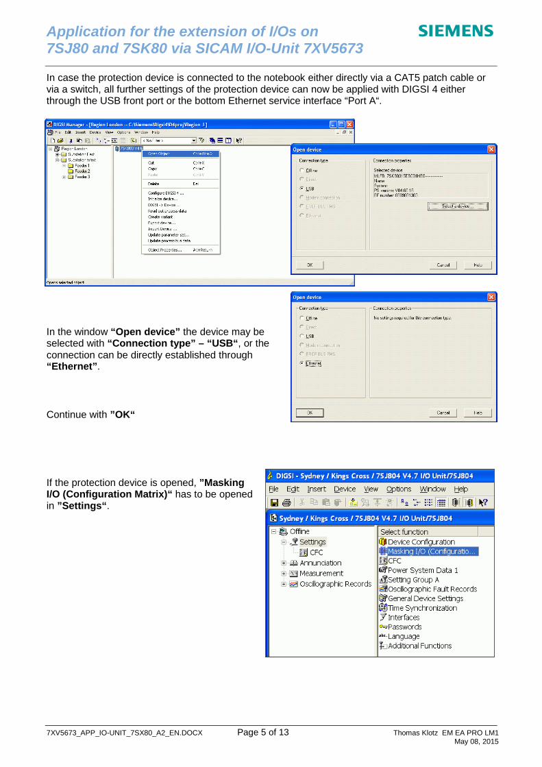
In case the protection device is connected to the notebook either directly via a CAT5 patch cable or via a switch, all further settings of the protection device can now be applied with DIGSI 4 either through the USB front port or the bottom Ethernet service interface “Port A“.
In the window “Open device” the device may be selected with “Connection type” – “USB“, or the connection can be directly established through “Ethernet”.
Continue with ”OK“
If the protection device is opened, ”Masking I/O (Configuration Matrix)“ has to be opened in ”Settings“.
Application for the extension of I/Os on s
7SJ80 and 7SK80 via SICAM I/O-Unit 7XV5673
7XV5673_APP_IO-UNIT_7SX80_A2_EN.DOCX Page 6 of 13 Thomas Klotz EM EA PRO LM1 May 08, 2015
All commands or signals that should be sent from the protection device to the binary outputs of the I/O-Unit have to be routed to “Destination CFC“
All commands or signals that should be received from the binary inputs of the I/O-Unit have to be routed to “Source CFC“. Usually these are user defined single point indications (here: SPOC1, SPOC2, SPOO) or blocking inputs of existing functions marked with a ´>´sign before the indication. Save with ”OK“
Application for the extension of I/Os on s
7SJ80 and 7SK80 via SICAM I/O-Unit 7XV5673
7XV5673_APP_IO-UNIT_7SX80_A2_EN.DOCX Page 7 of 13 Thomas Klotz EM EA PRO LM1 May 08, 2015
Configure the I/O-Unit in the CFC logic: Open ”CFC“ in ”Settings“. Then insert “CFC chart”. Open the CFC chart (“CFC(1)”) with double-click.
Select “I/O-Unit” from ”Other blocks” and drag the block with the left mouse key to the CFC chart. If you apply two I/O-Units select again an “I/O-Unit” from ”Other blocks” and drag it to the same CFC chart.
Select the correct CFC task level and connect the CFC block: Click the button “Run Sequence”. Then change the CFC task level by dragging the chart from “MW_BEARB” to “PLC1_BEARB (Slow PLC)”.
Go back into the chart by clicking the button “Run Sequence” again.
Application for the extension of I/Os on s
7SJ80 and 7SK80 via SICAM I/O-Unit 7XV5673
7XV5673_APP_IO-UNIT_7SX80_A2_EN.DOCX Page 8 of 13 Thomas Klotz EM EA PRO LM1 May 08, 2015
In the next step the IP address and the port number of the SICAM I/O-Unit have to be set. Therefore just click with the right mouse button into the I/O-Unit and select ”Object Properties”, sheet ”I/Os”. Then enter the right data for IP address (line 7 to line 10) and Port number (as HEX code in line 11) in column “Value”:
IP address of the first I/O-Unit: e.g. 192.168.10.55 Port number of the first I/O-Unit: e.g. 51000 (HEX code 16#C738)
IP address of the second I/O-Unit: e.g. 192.168.10.56 Port number of the second I/O-Unit: e.g. 51001 (HEX code 16#C739)
The 6 binary inputs of the SICAM I/O-Unit are denominated BI_N1 to BI_N3 and BI_P1 to BI_P3, whereas the 6 binary outputs of the SICAM I/O-Unit are denominated IR1 to IR6 (Indication from Remote). To connect a signal just click with the right mouse button into one of the inputs or outputs of the I/O-Unit and select ”Interconnection to Address”.
Then select the signal you want and click ”OK“. Afterwards repeat this procedure for each binary input and output that you want to use.
Application for the extension of I/Os on s
7SJ80 and 7SK80 via SICAM I/O-Unit 7XV5673
7XV5673_APP_IO-UNIT_7SX80_A2_EN.DOCX Page 9 of 13 Thomas Klotz EM EA PRO LM1 May 08, 2015
Finally click the “Compile button”. If the compilation is successful, the message “Process correctly executed” will be displayed.
If you want to use the CFC block output signal „CA“ (Communication Active) please refer to the description on the last page of this document!
Close the CFC chart and click the “Save” button.
Then press Device DIGSI to Device. The process will be completed by entering the password in the input box and then “OK“.
Note: Save settings to “file”.
Application for the extension of I/Os on s
7SJ80 and 7SK80 via SICAM I/O-Unit 7XV5673
7XV5673_APP_IO-UNIT_7SX80_A2_EN.DOCX Page 10 of 13 Thomas Klotz EM EA PRO LM1 May 08, 2015
Setting the I/O-Unit 7XV5673 by using a Web-Browser The settings of the I/O-Unit 7XV5673 are to be entered by using a PC/notebook through the Ethernet interface and a Web browser, e.g. Internet Explorer. Prior to starting the Web Browser some settings on PC/notebook must however be applied. As per default the I/O-Unit has the IP address 192.168.0.55. Note: Do not connect two SICAM I/O-Units to the network before you have changed the IP-addresses to different values because the I/O-Units have the same default IP-address. Preparing the PC/Notebook: To operate the I/O-Unit 7XV5673 with the Notebook both IP-Addresses must be in the same network segment. First check and set the IP-address of your Ethernet adapter:
For WIN XP: Start Settings Control Panel Network Connections. Then select the correct Ethernet adapter and continue with Properties TCP/IP Properties: Change IP-address to 192.168.0.3, select OK, then CLOSE.
This is the unique IP-address of your PC/Notebook Ethernet interface which must be different from the IP-address of other network participants.
Open I/O-Unit 7XV5673 Web Interface: Now start a Web-Browser (e.g. Internet-Explorer), enter the IP-Address 192.168.0.55, followed by ”Return“. The start window displays the current settings of the I/O-Unit. Configure “Communication Ethernet”: Initially the “Bus protocol / Operating mode“ is set to “Modbus TCP”. To operate the I/O-Unit on Port A of a 7SJ80 or 7SK80 the operating mode has to be changed to “Modbus UDP”. The “IP-Address“ you want to have (e.g. 190.168.10.55 as mentioned in the table on page 2) and the corresponding “Subnet Mask“ (e.g. 255.255.255.0) have to be set now. If a router is used, the Router IP address must be set in ”Default gateway“.
Application for the extension of I/Os on s
7SJ80 and 7SK80 via SICAM I/O-Unit 7XV5673
7XV5673_APP_IO-UNIT_7SX80_A2_EN.DOCX Page 11 of 13 Thomas Klotz EM EA PRO LM1 May 08, 2015
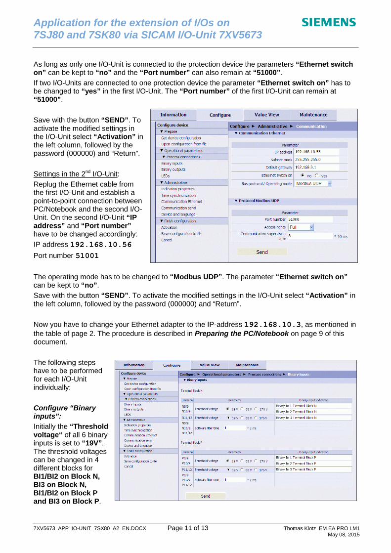
As long as only one I/O-Unit is connected to the protection device the parameters “Ethernet switch on” can be kept to “no” and the “Port number” can also remain at “51000”. If two I/O-Units are connected to one protection device the parameter “Ethernet switch on” has to be changed to “yes” in the first I/O-Unit. The “Port number” of the first I/O-Unit can remain at “51000”. Save with the button “SEND”. To activate the modified settings in the I/O-Unit select “Activation” in the left column, followed by the password (000000) and “Return”. Settings in the 2nd I/O-Unit: Replug the Ethernet cable from the first I/O-Unit and establish a point-to-point connection between PC/Notebook and the second I/O-Unit. On the second I/O-Unit “IP address” and “Port number” have to be changed accordingly: IP address 192.168.10.56 Port number 51001 The operating mode has to be changed to “Modbus UDP”. The parameter “Ethernet switch on” can be kept to “no”. Save with the button “SEND”. To activate the modified settings in the I/O-Unit select “Activation” in the left column, followed by the password (000000) and “Return”. Now you have to change your Ethernet adapter to the IP-address 192.168.10.3, as mentioned in the table of page 2. The procedure is described in Preparing the PC/Notebook on page 9 of this document. The following steps have to be performed for each I/O-Unit individually: Configure “Binary inputs”: Initially the “Threshold voltage“ of all 6 binary inputs is set to “19V”. The threshold voltages can be changed in 4 different blocks for BI1/BI2 on Block N, BI3 on Block N, BI1/BI2 on Block P and BI3 on Block P.
Application for the extension of I/Os on s
7SJ80 and 7SK80 via SICAM I/O-Unit 7XV5673
7XV5673_APP_IO-UNIT_7SX80_A2_EN.DOCX Page 12 of 13 Thomas Klotz EM EA PRO LM1 May 08, 2015
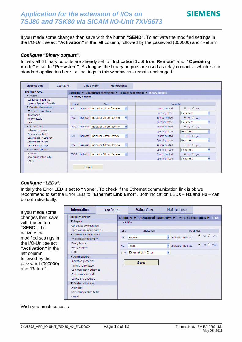
If you made some changes then save with the button “SEND”. To activate the modified settings in the I/O-Unit select “Activation” in the left column, followed by the password (000000) and “Return”. Configure “Binary outputs”: Initially all 6 binary outputs are already set to “Indication 1…6 from Remote“ and “Operating mode” is set to “Persistent”. As long as the binary outputs are used as relay contacts - which is our standard application here - all settings in this window can remain unchanged.
Configure “LEDs”: Initially the Error LED is set to “None“. To check if the Ethernet communication link is ok we recommend to set the Error LED to “Ethernet Link Error“. Both indication LEDs – H1 and H2 – can be set individually. If you made some changes then save with the button “SEND”. To activate the modified settings in the I/O-Unit select “Activation” in the left column, followed by the password (000000) and “Return”. Wish you much success
Application for the extension of I/Os on s
7SJ80 and 7SK80 via SICAM I/O-Unit 7XV5673
7XV5673_APP_IO-UNIT_7SX80_A2_EN.DOCX Page 13 of 13 Thomas Klotz EM EA PRO LM1 May 08, 2015
Use of the CFC block output signal „CA“ (Communication Active) The protection device checks cyclically if the SICAM I/O-Unit replies on request latest after 5 ms. The CFC block output “CA” goes into a High-level status if the communication between the protection device and the I/O-Unit is stable. In case the connection is not stable the status of “CA” will be changed to Low-level after 5 ms. If the output “CA” is directly routed through the DIGSI Matrix to an LED or a binary output, the signal will be sent instantaneously and it will be stored in the event list of the protection device. A simultaneous use of other Ethernet services, e.g. an access to the HTML pages of the Web-Server of the I/O-Unit, this might cause delays of around 20 to 30 ms in the communication between the protection device and the SICAM I/O-Unit. The signal “CA” might also be shown in this case which is misleading.
Because an access to the Web-Server of the I/O-Unit is also possible during service we recommend to add a timer of 50 ms in the CFC logic of the protection device to suppress those temporary Ethernet errors with a duration of up to 30 ms. The protection device will still be able to detect and show communication errors of more than 50 ms in service. Note: The I/O-Unit will show and store communication errors of more than 80 ms (default). The following CFC logic shows the combination of the output signal “CA“ from the CFC block “I/O-Unit“ and a negator “NEG“ and a simple timer ”TIMER_SHORT“.
If the Ethernet connection is stable, the timer is blocked by the High-level status of the output signal ”CA“ at its timer input “Reset”. If the Ethernet connection gets interrupted the timer input “Reset” will be released by the Low-level status of “CA”. At the same time the timer will be started by the High-level status of the negator. If the Low-level status on output “CA“ lasts longer than the set time of the CFC timer, the protection device will indicate a communication error as long as the communication is interrupted. The timer will be blocked and the indication on the protection device will be suppressed when the output ”CA“ reaches a High-level status before the CFC timer expires (e.g. 50 ms). Note: Please consider the correct CFC task level and run sequence of the CFC blocks.


![IO [Inorganic] Compendium Method IO-3.4: Determination of ...](https://static.documents.pub/doc/80x56/61bd108661276e740b0efce1/io-inorganic-compendium-method-io-34-determination-of-.jpg)


