Your rotary cutter is designed primarily for weed, grass and brush to 2” diameter. With proper maintenance as described in the manual, your cutter will provide you with years of dependable service with a minimum of repairs.
It is recommended that all operators of this implement read this manual or be instructed of its contents as to safety, proper operation, and maintenance before beginning operation.
Your cutter has been assembled for operation with a tractor PtO input speed of 540. Verify your RPm with your local dealer prior to operation. Should you desire to change PtO input speed, contact your local dealer. this series of cutter is recommended for use with tractors rated at 48 HP.
When ordering parts for the gear boxes and the drivelines, be sure to specify the serial number. the serial number is located on the angle located on top of cutter.
Chain guards, deflectors, driveline integral shields are standard equipment and need to be used at all times.
this Rotary Cutter is designed with care and built with quality materials by skilled workers. Proper assembly, maintenance, and operating practices, as described in this manual, will help the owner/operator get years of satisfactory service from the machine.
the purpose of this manual is to familiarize, instruct, and train. the assembly Section instructs the owner/operator in the correct assembly of the Cutter using standard and optional equipment. the Parts Listing section is designed to familiarize the owner/operator with replaceable parts on the Cutter. this section provides exploded assembly drawings of each cutter component illustrating each piece and the corresponding part number.
Careful use and timely service save extensive repairs and costly downtime losses. the Operation and maintenance Sections of the manual train the owner/operator how to work the Cutter correctly and attend to appropriate maintenance. the trouble Shooting Guide helps diagnose difficulties with cutter and offers solution to the problems.
Safety is of primary importance to the owner/operator and to the manufacturer. the first section of this manual includes a list of Safety messages, that, if followed, will help protect the operator and bystanders from injury or death. many of the Safety messages will be repeated throughout the manual. the owner/operator/dealer should know these Safety messages before assembly and be aware of the hazards of operating this rotary cutter during assembly, use, and maintenance. the Safety alert Symbol combined with a Signal Word, as seen below, is intended to warn the owner/operator of impending hazards and the degree of possible injury faced when operating this machine.
Indicates an imminently hazardous situation that, if not avoided, WILL result in DeatH ORVeRY SeRIOuS InJuRY.
Indicates an imminently hazardous situation that, if not avoided, COuLD result in DeatHOR SeRIOuS InJuRY.
Indicates an imminently hazardous situation that, if not avoided, maY result in mInORInJuRY.
Identifies special instructions or procedures that, if not strictly observed, could result indamage to, or destruction of the machine, attachments or the environment.
InTRoDUcTIon SEcTIon
caUTIon
waRnIng
DangER
8' & 10' Predatorrr Offset - 3
SaFETy SEcTIon
a safe and careful operator is the best operator. Safety is of primary importance to the manufacturer and should be to the owner/operator. most accidents can be avoided by being aware of your equipment, your surroundings, and observing certain precautions. the safety section of this manual includes a list of guidelines that, if followed, will help protect the operator and bystanders from injury or death. ReaD, unDeRStanD, and FOLLOW the following safety guidelines before assembling, operating or servicing this implement. Serious injury or death may occur unless care is taken to follow the warnings and instructions stated in these Safety guidelines. Practice all usual and customary safe working precautions and above all – remember safety is up to YOU. Only YOU can prevent serious injury or death from unsafe practices.
this equipment should only be operated by those persons who have read the manual, who are responsible and trained, and who know how to do so safely and responsibly.
Si no lee ingles, pida ayuda a alguien que si lo lea para que le traduzca las medidas de seguridad.
general Safety guidelines
• never operate the tractor or implement until you have read and completely understand this manual and the tractor operator’s manual. Learn how to stop the tractor engine suddenly in an emergency. never allow inexperienced or untrained personnel to operate the tractor and implement without supervision. make sure the operator has fully read and understood the manuals prior to operation.
• the operator and all support personnel should wear hard hats, safety shoes, safety glasses, and proper hearing protection at all times for protection from injury including injury from items that may be thrown by the equipment.
• never allow children to operate, ride on, play on or around, or come close to the tractor or implement. Children can slip or fall off the equipment and be injured or killed. usually, 16-17 year-old children who are mature and responsible can operate the implement with adult supervision, if they have read and understand the operator’s manuals, been trained in proper operation of the tractor and implement, and are physically large enough to reach and operate the controls easily.
• neVeR use drugs or alcohol immediately before or while operating the tractor and implement. Drugs and alcohol will affect an operator’s alertness and coordination and therefore affect the operator’s ability to operate the equipment safely. Before operating the tractor or implement, an operator on prescription or over-the-counter medication must consult a medical professional regarding any side effects of the medication that would hinder their ability to operate the equipment safely. neVeR knowingly allow anyone to operate this equipment when their alertness or coordination is impaired. Serious injury or death to the operator or others could result if the operator is under the influence of drugs or alcohol.
SaFETy SEcTIon
8' & 10' Predatorrr Offset - 5
• Prolonged tractor operation may cause operator boredom and fatigue affecting safe operation. take scheduled work breaks to help prevent these potentially impaired operating conditions. never operate the implement and tractor in a fatigued or bored mental state which impairs proper and safe operation.
• tractors with or without an implement attached can often be noisy enough to cause permanent hearing loss. We recommend that you always wear hearing protection if the noise in the operator’s position exceeds 80db. noise over 85db over an extended period of time will cause severe hearing loss. noise over 90db adjacent to the Operator over an extended period of time will cause permanent or total hearing loss.
Note: Hearing loss from loud noise [from tractors, chain saws, radios, and other such sources close to the ear] is cumulative over a lifetime without hope of natural recovery.
general Safety – Rotating Equipment
• the rotating parts of this machine continue to rotate even after the PtO has been turned off. the operator should remain in his seat for 60 seconds after the brake has been set, the PtO disengaged, the tractor turned off, and all evidence of rotation has ceased.
• Do not put hands or feet under implement decks. Blade contact can result in serious injury or even death. Stay away until all motion has stopped and the decks are securely blocked up.
• Do not operate the implement while wearing loose fitting clothing. entanglement of the clothing with the rotating elements can result in serious injury or even death. KeeP aWaY FROm ROtatInG eLementS to prevent entanglement and possible serious injury or death.
General Safety – Hot Surfaces & Fire Safety
• Follow these guidelines to reduce the risk of equipment and grass fires while operating, servicing, and repairing the tractor and/or implement:
· equip the tractor with a fire extinguisher in an accessible location.· Do not operate the implement on a tractor with an underframe exhaust.· Do not smoke or have an open flame near the tractor and/or implement.· Do not drive into burning debris or freshly burnt areas.· ensure slip clutches are properly adjusted to prevent excessive slippage and plate heating.· never allow clippings or debris to collect near drivelines, slip clutches, and gearboxes.
• avoid contact with hot surfaces including hydraulic oil tanks, pumps, motors, valves and hose connections, engine or muffler. Relieve hydraulic pressure before performing maintenance or repairs. use gloves and eye protection when servicing hot components. Contact with a hot surface or fluid can cause serious injury from burns or scalding.
SaFETy SEcTIon
6 - 8' & 10' Predatorrr Offset
Equipment operation Safety
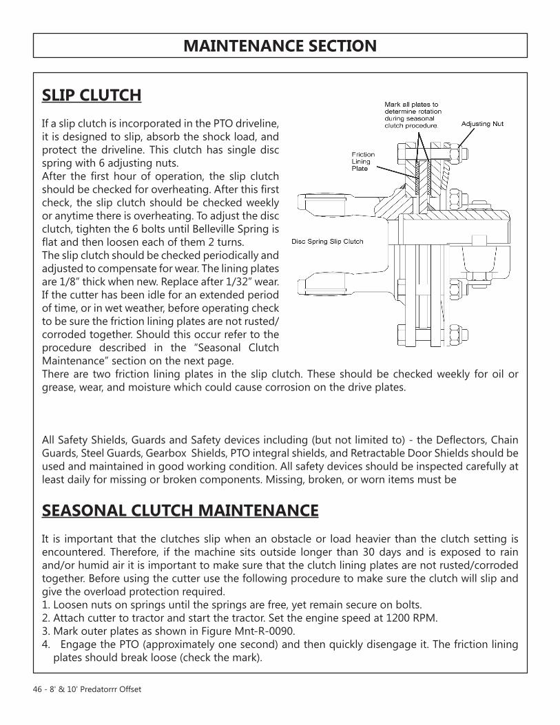
• all Safety Shields, Guards and Safety devices including (but not limited to) - the Deflectors, Chain Guards, Steel Guards, Gearbox Shields, PtO integral shields, and Retractable Door Shields should be used and maintained in good working condition.
• all safety devices should be inspected carefully at least daily for missing or broken components. missing, broken, or worn items must be replaced at once. Broken or worn blades must be replaced with neW blades to reduce the possibility of injury or death from thrown objects, entanglement, or blade contact. neVeR attemPt tO StRaIGHten, WeLD, OR WeLD HaRDFaCInG On BLaDeS SInCe tHIS WILL LIKeLY CRaCK OR OtHeRWISe DamaGe tHe BLaDe WItH SuBSeQuent FaILuRe anD POSSIBLe SeRIOuS InJuRY FROm tHROWn BLaDeS.
• Operate the tractor and/or implement controls only while seated in the tractor seat with the seat belt securely fastened around you. Inadvertent movement of the tractor or implement may cause serious injury or death. Do not mount/dismount the tractor while the tractor or implement parts are moving. mount the tractor only when the tractor and all moving parts are completely stopped.
• BeFORe leaving the tractor seat, always engage the brake and/or set the tractor transmission in parking gear, disengage the PtO, stop the engine, remove the key, and wait for all moving parts to stop. Place the tractor shift lever into a low range or parking gear to prevent the tractor from rolling. never dismount a tractor that is moving or while the engine is running.
• never leave the tractor and implement unattended while the implement is in the lifted position. accidental operation of lifting lever or a hydraulic failure may cause sudden drop of unit possibly resulting in injury or death by crushing. Lower the implement carefully to the ground. Do not put hands or feet under lifted components.
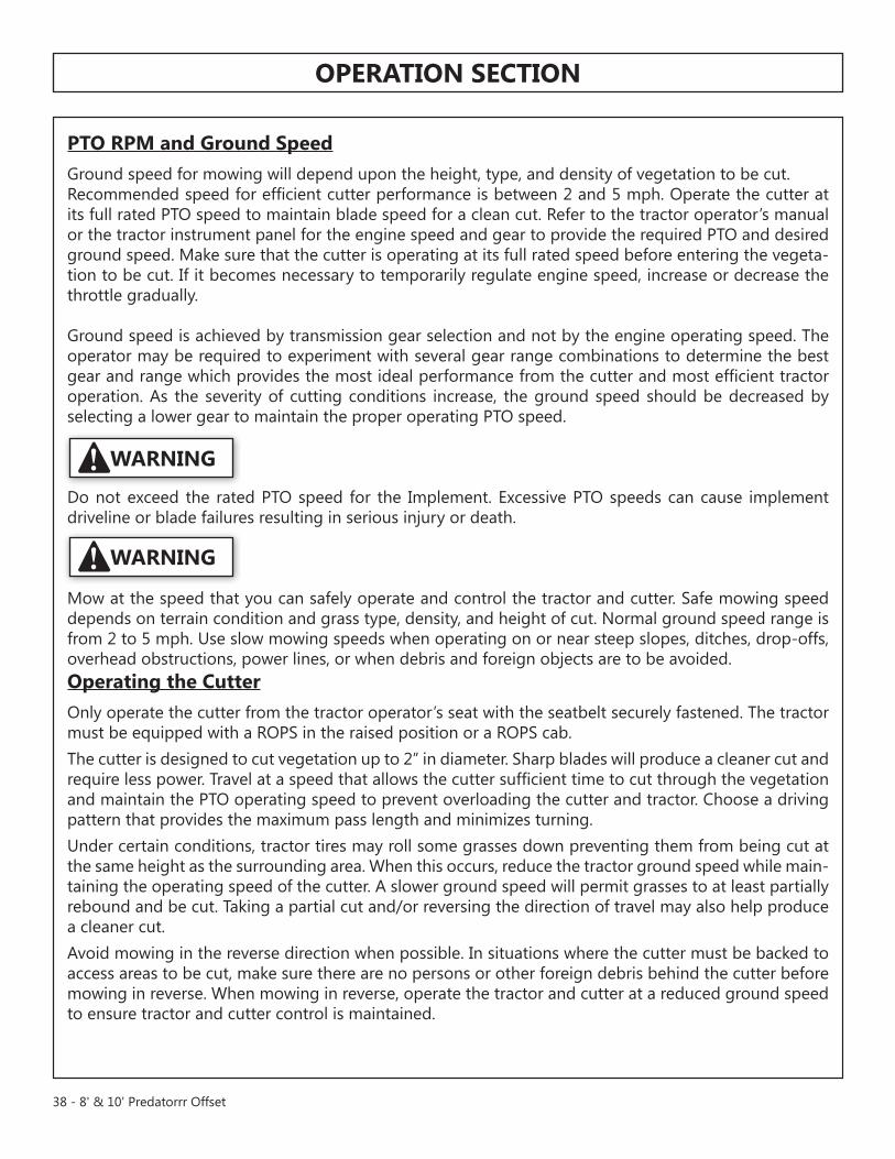
• Do not exceed the rated PtO speed for the implement. excessive PtO speeds can cause implement driveline or blade failures resulting in serious injury or death.
• make sure the PtO shield, integral driveline shields, and input shields are installed when using PtO-driven equipment.
• DO nOt operate this implement on a tractor that is not properly maintained. In case of mechanical difficulty during operation, place the transmission in the park position, set the parking brake, shut down all power, including the PtO and the engine and remove the key. Wait until all rotating motion has stop before dismounting and perform repairs before resuming operation. Serious injury and possible death could occur from not maintaining this implement and tractor in good operating condition.
• Do not operate implement if excessive vibration exists. Shut down PtO and the tractor engine. Inspect the implement to determine the source of the vibration. If implement blades are missing
SaFETy SEcTIon
8' & 10' predatorrr Offset - 7
or damaged replace them immediately. Do not operate the implement until the blades have been replaced and the implement operates smoothly. Operating the implement with excessive vibration can result in component failure and broken objects to be thrown outward at very high velocities. to reduce the possibility of property damage, serious injury, or even death, never allow the implement to be operated with blades missing.
• Do not operate this equipment with hydraulic oil or fuel leaking. Oil and fuel are explosive and their presence could present a hazard. Do not check for leaks with your hand! High-pressure oil streams from breaks in the line could penetrate the skin and cause tissue damage.
- to check for a hose leak, SHut the tractor enGIne OFF and remove all hydraulic pressure. Wear oil impenetrable gloves, safety glasses and use cardboard to check for evidence of oil leaks.
- If you suspect a leak, RemOVe the HOSe and have it tested at a Dealer. If oil does penetrate the skin, have the injury treated immediately by a physician knowledgeable and skilled in this procedure. always read carefully and comply fully with the manufacturer’s instructions when handling oil, solvents, cleansers, and any other chemical agent.
• mow at the speed that you can safely operate and control the tractor and implement. Safe mowing speed depends on terrain condition and grass type, density, and height of cut. normal ground speed range is from 2 to 5 mph. use slow mowing speeds when operating on or near steep slopes, ditches, drop-offs, overhead obstructions, power lines, or when debris and foreign objects are to be avoided.
• avoid mowing in reverse direction when possible. Check to make sure there are no persons behind the implement and use extreme care when mowing in reverse. mow only at a slow ground speed where you can safely operate and control the tractor and implement. never mow an area that you have not inspected and removed debris or foreign material.
• the implement is designed for certain mowing applications and is rated to cut up to a specific size vegetation (see implement Standard equipment and Specifications). DO nOt use this implement to cut vegetation above the implement’s rated capacity or to cut any type of non-vegetative material. Only operate this implement on a properly sized and equipped tractor. Operating this implement in an application for which it is not designed and/or operating the implement with the wrong size tractor can cause implement component damage and equipment failure resulting in possible serious injury or death.
• Do not operate or pull the implement into standing water. When uplift or fan type implement blades contact water they can be severely deflected downward causing possible failure of blade resulting in serious boldly injury to the operator or bystanders.
• Do not mow with two machines in the same area except with cab tractors with the windows closed.
SaFETy SEcTIon
8 - 8' & 10' predatorrr Offset
• Do not turn so sharp or lift implement so high to produce a severe “knocking” of the driveline which will cause accelerated wear and breakage of drive train components and could result in possible injury from the separated Driveline sections.
• Periodically shut down the tractor and implement and clean clippings and collected debris from the implement deck. DO nOt approach the implement unless the tractor is turned off and all motion has ceased.
• never crawl under a raised implement supported solely by the tractor 3-Point hitch. Release of the control lever or mechanical failure will result in the implement falling and possible injury or death. always securely block up the implement before crawling underneath to perform repairs and service. DO nOt allow any person under a folded wing unless wing is securely locked up or supported.
Equipment operation Safety – clearances and obstructions
• Rotary implements are capable under adverse conditions of throwing objects for great distances (300 feet or more) and causing serious injury or death. Follow safety guidelines carefully.
• StOP mOWInG IF PaSSeRSBY aRe WItHIn 100 YaRDS
• Be sure you have adequate knowledge of the property you will be working on. take time to make yourself aware of any area underground lines or cables. always keep a careful lookout and use extreme care when working around utility and municipal obstructions. never allow the implement to contact any utility, municipal, or other type structure. Clearly mark all mowing obstructions and consult local utility providers for a safe code of operation.
• mow only in conditions where you have clear visibility in daylight or with adequate artificial lighting. never mow in darkness or foggy conditions where you cannot clearly see at least 100 yards in front and to the sides of the tractor and implement. make sure that you can clearly see and identify passersby, steep slopes, ditches, drop-offs, overhead obstructions, power lines, debris and foreign objects. If you are unable to clearly see these types of items discontinue mowing.
• this implement maybe wider than the tractor. Be careful when operating or transporting this equipment to prevent the implement from running into or striking sign posts, guard rails, concrete abutments or other solid objects. Such an impact could cause the implement and tractor to pivot violently resulting in loss of steering control, serious injury, or even death. never allow the implement to contact obstacles.
SaFETy SEcTIon
8' & 10' predatorrr Offset - 9
• the rotating parts of this machine have been designed and tested thoroughly. However, the blades could fail upon impact with heavy, solid objects such as metal guard rails and concrete structures. Such impact could cause the broken objects to be thrown outward at very high velocities. to reduce the possibility of property damage, serious injury, or even death, never allow the cutting blades to contact such obstacles.
• extreme care should be taken when operating near loose objects such as gravel, rocks, wire, and other debris. Inspect the area before mowing. Foreign objects should be removed from the site to prevent machine damage and/or bodily injury or even death. any objects that cannot be removed must be clearly marked and carefully avoided by the operator. Stop mowing immediately if blades strike a foreign object. Repair all damage and make certain rotor or blade carrier is balanced before resuming mowing.
• this machine is often operated in heavy brush and in heavy weeds. the blades of this implement can throw objects if shields are not properly installed and maintained. Serious injury or even death may occur unless care is taken to insure the safety of the operator, bystanders, or passersby in the area. Do not operate this machine with anyone in the immediate area. Stop mowing if anyone is within 100 yards of implement.
Note: Where there are grass and weeds high enough to hide debris that could be struck by the blades, the area should be: inspected and large debris removed, mowed at an intermediate height, inspected, closely with any remaining debris being removed, and mowed again at desired final height. (This will also reduce power required to mow, reduce wear and tear on the implement drivetrain, spread cut material better, eliminate streaking, and make the final cut more uniform).
• many varied objects, such as wire, cable, rope, or chains, can become entangled in the operating parts of the implement head. these items could then swing outside the housing at greater velocities than the blades. Such a situation is extremely hazardous and could result in serious injury or even death. Inspect the cutting area for such objects before mowing. Remove any like object from the site. never allow the cutting blades to contact such items.
• Do not let the blades turn when the implement deck is raised for any reason, including clearance or for turning. Raising the implement deck exposes the cutting blades which creates a potentially serious hazard and could cause serious injury or even death from objects thrown from the blades.
• Do not operate this equipment in areas where insects such as bees may attack you and/or cause you to lose control of the equipment. If you must enter in such areas, use a tractor with an enclosed cab and close the windows to prevent insects from entering. If a tractor cab is not available, wear suitable clothing including head, face, and hand protection to shield you from the insects. attacking insects can cause you to lose control of the tractor, which can result in serious injury or death to you or bystanders. never dismount a moving tractor.
SaFETy SEcTIon
10 - 8' & 10' predatorrr Offset
connecting or Disconnecting Implement Safety
• always shut the tractor completely down, place the transmission in park, and set the parking brake before you or anyone else attempts to connect or disconnect the implement and tractor hitches.
• DO nOt use a PtO adapter to attach a non-matching implement driveline to a tractor PtO. use of an adapter can double the operating speed of the implement resulting in excessive vibration, thrown objects, and blade and implement failure. adapter use will also change the working length of the driveline exposing unshielded driveline areas. Serious bodily injury and/or equipment failure can result from using a PtO adapter. Consult an authorized dealer for assistance if the implement driveline does not match the tractor PtO.
• When attaching the implement input driveline to the tractor PtO, it is important that the connecting yoke spring activated locking collar slides freely and the locking balls are seated securely in the groove on the tractor PtO shaft. a driveline not attached correctly to the tractor PtO shaft could come loose and result in personal injury and damage to the implement.
• Before operating the implement, check to make sure the implement input driveline will not bottom out or become disengaged. Bottoming out occurs when the inner shaft penetrates the outer housing until the assembly becomes solid-it can shorten no more. Bottoming out can cause serious damage to the tractor PtO by pushing the PtO into the tractor and through the support bearings or downward onto the PtO shaft, breaking it off. a broken drive line can cause personal injury.
SaFETy SEcTIon
8' & 10' predatorrr Offset - 11
Transporting Safety
• Only tow the implement behind a properly sized and equipped tractor which exceeds the weight of the implement by at least 20%. DO nOt tow the implement behind a truck or other type of vehicle. never tow the implement and another implement connected in tandem.
• make certain before transporting that a “Slow moving Vehicle” (SmV) sign is installed in such a way as to be clearly visible and legible. When transporting the implement use the tractor flashing warning lights and follow all local traffic regulations.
• Your driving vision may be reduced or impaired by the tractor, cab, or implement. Before driving on public roadways identify any limited vision areas, and make adjustments to your operating position, mirrors, and the implement transport position so that you can clearly see the area where you will be traveling, and any traffic that may approach you. Failure to maintain adequate vision of the public roadway and traffic can result in serious injury or even death.
• understand the tractor and implement and how it handles before transporting on streets and highways. make sure the tractor steering and brakes are in good condition and operate properly.
• transport only at speeds where you can maintain control of the equipment. Serious accidents and injuries can result from operating this equipment at high speeds. Before transporting the tractor and implement, determine the proper transport speeds for you and the equipment. make sure you abide by the following rules:
- test the tractor at a slow speed and increase the speed slowly. apply the Brakes smoothly to determine the stopping characteristics of the tractor and implement. as you increase the speed of the tractor the stopping distance increases. Determine the maximum transport speed not to exceed 20 mph (30 kph) for towing this equipment.
- test the equipment at a slow speed in turns. Increase the speed through the turn only after you determine that it is safe to operate at a higher speed. use extreme care and reduce your speed when turning sharply to prevent the tractor and implement from turning over. Determine the maximum safe turning speed for you and this equipment before operating on roads or uneven ground.
SaFETy SEcTIon
12 - 8' & 10' Predatorrr Offset
- Be aware of the operating conditions. Do not operate the tractor with weak or faulty brakes or worn tires. When operating down a hill or on wet or rain slick roads, the braking distance increases: use extreme care and reduce your speed. When operating in traffic always use the tractor’s flashing warning lights and reduce your speed. Be aware of traffic around you and watch out for the other guy.
• turn curves or go up hills only at a low speed and using a gradual steering angle. Rear mounted implements move the center of gravity to the rear and remove weight from the front wheels. make certain, by adding front ballast, that at least 20% of the tractor’s weight is on the front wheels to prevent rearing up, loss of steering control or tractor tip-over.
• Slow down on rough or uneven surfaces to prevent loss of steering control which could result in property damage or possible injury. Do not transport unless 3-Point lift lever is fully raised and in the latched transport position. Dropping implement in transport can cause serious damage to the tractor and/or implement and possibly cause the operator or others to be injured or killed.
• In wet conditions where there is a likelihood of material collecting on the implement, make certain that excess material is removed before traveling on public roadways.
• allow sufficient clearance for the implement to swing outward while turning. Implements carried behind the tractor will swing outside the tire path when making turns. Contacting a solid object while turning will cause equipment damage and possible injury.
Maintenance and Service Safety
• Periodically inspect all moving parts for wear and replace when necessary with authorized service parts. Look for loose fasteners, worn or broken parts, and leaky or loose fittings. make sure all pins have cotter pins and washers. Serious injury may occur from not maintaining this machine in good working order.
• Perform service, repairs and lubrication according to the maintenance section. ensure the unit is properly lubricated as specified in the lubrication schedule and all bolts and nuts have proper torque. Failure to properly service, repair and maintain this implement in good operating condition could cause component failure and possible serious injury or even death.
• use extreme caution when getting onto the implement to perform repairs, maintenance and when removing accumulated material. Only stand on solid flat surfaces to ensure good footing. Slipping and falling can cause serious injury or death.
SaFETy SEcTIon
8' & 10' Predatorrr Offset - 13
Maintenance and Service Safety continued
• never work under the implement, the framework, or any lifted component unless the implement is securely supported or blocked up to prevent sudden or inadvertent falling which could cause serious injury or even death.
• never attempt to lubricate, adjust, or remove material from the implement while it is in motion or while tractor engine is running. make sure the tractor engine is off, the transmission in park, the parking brake set, and that the key is with you before working on the implement.
• always disconnect the main PtO Driveline from the tractor before performing service on
the implement. never work on the implement with the tractor PtO driveline connected and running. Rotating Parts, blades or drivelines could turn without warning and cause immediate entanglement, injury or death.
• DO nOt weld or repair rotating implement components. Welds and other repairs may cause severe vibration and/or component failure resulting in part being thrown from the implement causing serious bodily injury. See your authorized Dealer for proper repair procedures.
• DO nOt weld or perform hot work on galvanized implements. Heating/burning of galvanizing material may release fumes which can be harmful to your health. (If applicable)
• Do not modify or alter this implement. Do not permit anyone to modify or alter this implement, any of its components or any implement function.
SaFETy SEcTIon
14 - 8' & 10' Predatorrr Offset
Parts Information
• modern ag implements use balanced and matched system components for blade carriers, blades, cuttershafts, knives, knife hangers, rollers, drivetrain components, and bearings. these parts are made and tested to modern ag specifications. always replace blades with original equipment manufacturer balanced blade sets. non-genuine “will fit” parts do not consistently meet these specifications. the use of “will fit” parts may reduce implement performance, void warranties, and present a safety hazard. use genuine modern ag implement parts for economy and safety.
Safety Signs/Decals
• modern ag supplies safety decals on this product to promote safe operation. Damage to the decals may occur while in shipping, use, or reconditioning. always maintain the safety signs in good readable condition. If the safety signs are missing, damaged, or unreadable, obtain and install replacement safety signs immediately.
concluding Safety Instructions and Practices
• In addition to the design and configuration of this implement, including safety signs and safety equipment, hazard control and accident prevention are dependent upon the awareness, concern, prudence, and proper training of personnel involved in the operation, transport, maintenance, and storage of the machine. Refer also to safety guidelines and operation instruction in each of the appropriate sections of the tractor and equipment manuals. Pay close attention to the Safety Signs affixed to the tractor and equipment.
SaFETy SEcTIon
8' & 10' Predatorrr Offset - 15
16 - 8' & 10' Predatorrr Offset
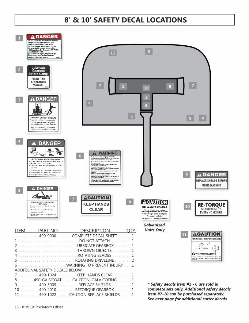
8' & 10' SaFETy DEcaL LocaTIonS
* Safety decals item #1 - 6 are sold in complete sets only. Additional safety decals item #7-10 can be purchased separately. See next page for additional cutter decals.
Our rotary cutters are manufactured with quality material by skilled workers. these cutters are designed to cut grass, weeds, crop stalks, brush and other vegetation up to 2” diameter. the cutter is equipped with protective deflectors and/or chain guards to prevent objects being thrown from the cutter by the blades, however, no shielding is 100% effective. all shields, guards, deflectors, and chains equipped on the unit must be maintained on the cutter in good operational condition.It is the operator’s responsibility to be knowledgeable of all potential operating hazards and to take every reasonable precaution to ensure oneself, others, animals, and property are not injured or damaged by the cutter, tractor, or a thrown object. Do not operate the cutter if passersby, pets, livestock, or property are within 300 feet of the unit.this section of the Operator’s manual is designed to familiarize, instruct, and educate safe and proper cutter use to the operator. Pictures contained in this section are intended to be used as a visual aid to assist in explaining the operation of a single spindle cutter and are not necessarily of all cutters. Some pictures may show shields removed for picture clarity. neVeR OPeRate this implement without all shields in place and in good operational condition. the operator must be familiar with the cutter and tractor operation and all associated safety practices before operating the cutter and tractor. Proper operation of the cutter, as detailed in this manual, will help ensure years of safe and satisfactory use of the cutter.IMPoRTanT: to avoid cutter damage, retorque all bolts after the first 10 hours of operation. Retighten blade carrier retaining nut on gearbox lower shafts to 450 ft. lbs.REaD anD UnDERSTanD THE EnTIRE oPERaTIng InSTRUcTIonS anD SaFETy SEcTIon oF THIS ManUaL anD THE TRacToR ManUaL BEFoRE aTTEMPTIng To USE THE TRacToR anD cutter. If you do not understand any of the instructions, contact your nearest authorized dealer for a full explanation. Pay close attention to all safety signs and safety messages contained in this manual and those affixed to the cutter and tractor.
ReaD, unDeRStanD, and FOLLOW the following Safety messages. Serious injury or death may occur unless care is taken to follow the warnings and instructions stated in the Safety messages. always use good common sense to avoid hazards.
Si no lee ingles, pida ayuda a alguien que si lo lea para que le traduzca lasmedidas de seguridad.
*Safety Deflectors are standard equipment. Single and double chain guards are available as extra equipment at extra cost. Modern recommends cutters be equipped with deflectors or double chain guards for all mowing purposes. Single chain guards may be used for agriculture purposes only and are specifically not recommended for highway, right-of-way, parks or greenbelt mowing.
**Ratings based on actual field performance.
oPERaTIon SEcTIon
20 - 8' & 10' Predatorrr Offset
oPERaTIon SEcTIon
oPERaToR REQUIREMEnTSSafe operation of the unit is the responsibility of a qualified operator. a qualified operator has read and understands the implement and tractor Operator’s manuals and is experienced in implement and tractor operation and all associated safety practices. In addition to the safety messages contained in this manual, safety decals are affixed to the implement and tractor. If any part of the operation and safe use of this equipment is not completely understood, consult an authorized dealer for a complete explanation.
If the operator cannot read the manuals for themselves or does not completely understand the operation of the equipment, it is the responsibility of the supervisor to read and explain the manuals, safety practices, and operating instructions to the operator.
Safe operation of equipment requires that the operator wear approved Personal Protective equipment (PPe) for the job conditions when attaching, operating, servicing, and repairing the equipment. PPe is designed to provide operator protection and includes the following safety wear:
PERSonaL PRoTEcTIVE EQUIPMEnT (PPE)• Protective eye Glasses, Goggles,
or Face Shield• Hard Hat• Steel toe Safety Footwear• Gloves• Hearing Protections• Close Fitting Clothing• Respirator or Filter mask (depends on mowing conditions)
neVeR use drugs or alcohol immediately before or while operating the tractor and Implement. Drugs and alcohol will affect an operator’s alertness and coordination and therefore affect the operator’s ability to operate the equipment safely. Before operating the tractor or Implement, an operator on prescription or over-the-counter medication must consult a medical professional regarding any side effects of the medication that would hinder their ability to operate the equipment safely. neVeR knowingly allow anyone to operate this equipment when their alertness or coordination is impaired. Serious injury or death to the operator or others could result if the operator is under the influence of drugs or alcohol.
2. OPERATOR REQUIREMENTSSafe operation of the unit is the responsibility of a qualified operator. A qualified operator has read andunderstands the implement and tractor Operator’s Manuals and is experienced in implement and tractoroperation and all associated safety practices. In addition to the safety messages contained in this manual,safety decals are affixed to the implement and tractor. If any part of the operation and safe use of thisequipment is not completely understood, consult an authorized dealer for a complete explanation.
If the operator cannot read the manuals for themselves or does not completely understand the operation of theequipment, it is the responsibility of the supervisor to read and explain the manuals, safety practices, andoperating instructions to the operator.
Safe operation of equipment requires that the operator wear approved Personal Protective Equipment (PPE)for the job conditions when attaching, operating, servicing, and repairing the equipment. PPE is designed toprovide operator protection and includes the following safety wear:
PERSONAL PROTECTIVE EQUIPMENT (PPE)
• Protective Eye Glasses, Goggles, or Face Shield
• Hard Hat• Steel Toe Safety Footwear• Gloves• Hearing Protections• Close Fitting Clothing• Respirator or Filter Mask (depends on mowing
conditions) OPS-U- 0002
NEVER use drugs or alcohol immediately before or while operating theTractor and Implement. Drugs and alcohol will affect an operator’salertness and coordination and therefore affect the operator’s ability to
operate the equipment safely. Before operating the Tractor or Implement, an operator onprescription or over-the-counter medication must consult a medical professional regardingany side effects of the medication that would hinder their ability to operate the Equipmentsafely. NEVER knowingly allow anyone to operate this equipment when their alertness orcoordination is impaired. Serious injury or death to the operator or others could result if theoperator is under the influence of drugs or alcohol. (SG-27)
DangER
8' & 10' Predatorrr Offset - 21
oPERaTIon SEcTIon
TRacToR REQUIREMEnTSthe tractor used to operate the cutter must have the power capacity to lift, pull, and operate the Power take Off (PtO) at the cutter’s rated speed while traveling at a ground speed between 2 and 5 mPH. Operating the cutter with a tractor that does not meet the following requirements may cause tractor or cutter damage and be a potential danger to the operator and passersby.
RoPS and Seat Beltthe tractor must be equipped with a Roll-Over-Protective-Structure (ROPS) (tractor cab or roll-bar) and seat belt to protect the operator from falling off the tractor, especially during a roll over where the driver could be crushed and killed. Only operate the tractor with the ROPS in the raised position and seat belt fastened. tractor model not equipped with a ROPS and seat belt should have these life saving features installed by an authorized dealer.
Operate this equipment only with a tractor equipped with an approved rollover-protective system (ROPS). always wear seat belts. Serious injury or even death could result from falling off the tractor--particularly during a turnover when the operator could be pinned under the ROPS.
Tractor Safety DevicesIf transporting or operating the tractor and cutter near a public roadway, the tractor must be equipped with proper warning lighting and a Slow moving Vehicle (SmV) emblem which are clearly visible from the rear of the unit. Lights and a SmV emblem must be equipped directly on implements if the visibility of the tractor warning signals are obscured. maintain all manufacturer equipped safety shields and guards. always replace shields and guards that were removed for access to connect, service, or repair the tractor or cutter. never operate the tractor PtO with the PtO master shield missing or in the raised position.
*Ratings are based upon field performance.
waRnIng
22 - 8' & 10' Predatorrr Offset
oPERaTIon SEcTIon
Do noT use a PtO adapter to attach a non-matching Implement driveline to a tractor PtO. use of an adapter can double the operating speed of the Cutter resulting in excessive vibration, thrown objects, and blade and cutter failure. adapter use will also change the working length of the driveline exposing unshielded driveline areas. Serious bodily injury and/or equipment failure can result from using a PtO adapter. Consult an authorized dealer for assistance if the Implement driveline does not match the tractor PtO.
never operate the tractor and Cutter if the Implement input driveline is directly connected to the tractor transmission. tractor braking distances can be substantially increased by the momentum of the rotating Cutter blades driving the tractor transmission even though the tractor clutch has been disengaged. Install an over running clutch between the tractor PtO and the Cutter driveline to prevent this potentially dangerous situation.
Tire SpacingRefer to the tractor Operator’s manual or consult an authorized dealer for instructions to change tractor tire spacing.
gETTIng on anD oFF THE TRacToRBefore getting onto the tractor, the operator must read and completely understand the implement and tractor operator manuals. If any part of either manual is not completely understood, consult an authorized dealer for a complete explanation.
Do not mount the tractor while the tractor is moving. mount the tractoronly when the tractor and all moving parts are completely stopped.
waRnIng
waRnIng
DangER
8' & 10' Predatorrr Offset - 23
oPERaTIon SEcTIon
Tractor Horsepowerthe power required to operate a cutter is determined by the tractor PtO horsepower. Operating the cutter with a tractor that does not have adequate power may damage the tractor engine.
3-Point Hitchthe tractor 3-point hitch must be rated to lift at least 1000 lbs.
Refer to the tractor operator’s manual for the category of the tractor being used. If the hitchdoes not conform to aSae dimensions, the cutter may not fit or raise properly.
Depending on the hitch category, certain size pins are used to attach the cutter to the tractor. Cat I hitches require 7/8” lower and 3/4” upper diameter hitch pins.
Front End weighta minimum of 20% total tractor weight must be maintained on the tractor front end at all times. Front end weight is critical to maintain steering control and to prevent the tractor from rearing up while driving. If the front end is too light, add weight until a minimum of 20% total weight is reached on the front tires. Front weights and weight carriers can be purchased through an authorized tractor dealership.
Power Take off (PTo)this cutter is designed to operate at a PtO speed of 540. most tractors operate at either 540, or acombination of 540 and 1000 RPm PtO speeds. the operating speed of the cutter and tractor can be determined by the number of splines on the driveline yoke and PtO output shaft. those operating at 540 RPm will have a 6-spline shaft and those operating at 1000 RPm will have a 21-spline shaft.
If operating an older model tractor where the tractor’s transmission and PtO utilize one master clutch, an over-running clutch must be used between the PtO output shaft and the driveline of the cutter. an authorized tractor dealer can provide the over-running clutch and its installation if needed.
24 - 8' & 10' Predatorrr Offset
oPERaTIon SEcTIon
Boarding the Tractoruse both hands and equipped handrails and steps for support when boarding the tractor. never use control levers for support when mounting the tractor. Seat yourself in the operator’s seat and secure the seat belt around you.
never allow passengers to ride on the tractor or attached equipment. Riders can easily fall off and be seriously injured or killed from falling off and being run over. It is the operator’s responsibility to forbid all extra riders at all times.
never allow children to operate, ride on, or come close to the tractor or Implement. usually, 16-17 year-old children who are mature and responsible can operate the implement with adult supervision, if they have read and understand the Operator’s manuals, been trained in proper operation of the tractor and Implement, and are physically large enough to reach and operate the controls easily.
never allow children or other persons to ride on the tractor or Implement. Falling off can result in serious injury or death.
Dismounting the Tractor
Before dismounting, park the tractor and implement on a reasonably level surface, apply the parking brake, idle the engine down, disengage the PtO, and lower the implement to the ground. Shut down the tractor engine according to the operator’s manual, remove the key, and wait for all motion to completely stop. never leave the seat until the tractor, its engine and all moving parts have come to a complete stop.
use hand rails and steps when exiting the tractor. Be careful of your step and use extra caution when mud, ice, snow or other matter has accumulated on the steps or hand rails. use all handrails and steps for support and never rush or jump off the tractor.
BeFORe leaving the tractor seat, always engage the brake and/or set the tractor transmission in parking gear, disengage the PtO, stop the engine, remove the key, and wait for all moving parts to stop. Place the tractor shift lever into a low range or parking gear to prevent the tractor from rolling. never dismount a tractor that is moving or while the engine is running. Operate the tractor controls from the tractor seat only.
4.1 Boarding the TractorUse both hands and equipped handrails and steps for support when boarding the tractor. Never use controllevers for support when mounting the tractor. Seat yourself in the operator’s seat and secure the seat beltaround you.
Never allow passengers to ride on the tractor or attached equipment. Riders can easily fall off and beseriously injured or killed from falling off and being ran over. It is the operator’s responsibility to forbid all extrariders at all times. OPS-U- 0008
Never allow children to operate, ride on, or come close to the Tractor orImplement. Usually, 16-17 year-old children who are mature andresponsible can operate the implement with adult supervision, if they
have read and understand the Operator’s Manuals, been trained in proper operation of thetractor and Implement, and are physically large enough to reach and operate the controlseasily. (SG-11)
Never allow children or other persons to ride on the Tractor or Implement.Falling off can result in serious injury or death. (SG-10)
4.2 Dismounting the TractorBefore dismounting, park the tractor and implement on a reasonably level surface, apply the parking brake,idle the engine down, disengage the PTO, and lower the implement to the ground. Shut down the tractorengine according to the operator’s manual, remove the key, and wait for all motion to completely stop. Neverleave the seat until the tractor, its engine and all moving parts have come to a complete stop.
Use hand rails and steps when exiting the tractor. Be careful of your step and use extra caution when mud,ice, snow or other matter has accumulated on the steps or hand rails. Use all handrails and steps for supportand never rush or jump off the tractor. OPS-U- 0009
BEFORE leaving the tractor seat, always engage the brake and/or setthe tractor transmission in parking gear, disengage the PTO, stop theengine, remove the key, and wait for all moving parts to stop. Place the
tractor shift lever into a low range or parking gear to prevent the tractor from rolling. Neverdismount a Tractor that is moving or while the engine is running. Operate the Tractorcontrols from the tractor seat only. (SG-9)
DangER
DangER
DangER
8' & 10' Predatorrr Offset - 25
oPERaTIon SEcTIon
connEcTIng THE cutter To THE TRacToRuse extreme caution when connecting the cutter to the tractor. the cutter should be securely resting at ground level or setting on blocks. Keep hands and feet from under the cutter deck and clear of pinch points between the tractor hitch arms and cutter pins.
always shut the tractor completely down, place the transmission in park, and set the parking brake before you or anyone else attempts to connect or disconnect the Implement and tractor hitches.
connecting cutter-Lift Type1. make sure the tractor is equipped with the
correct PtO shaft. Change shafts if needed.2. Shorten or remove the tractor drawbar to
avoid interference when raising and lowering the cutter.
3. Board the tractor and start the engine. Position the tractor to the cutter with the 3-point lift arms positioned at the same height and to the outside of the cutter hitch pins.
4. turn off the tractor engine and dismount.5. One lift arm at a time, align arm end hole with the a frame lift pins. mount lift arms on lift pin
and retaining pin into hitch pin.6. Walk around to opposite side and repeat procedure for remaining lift arm and hitch pin.7. extend or retract 3-point top link to align its end hole with the holes of the cutter’s top link.
Insert the top link hitch pin and insert retaining pin into hitch pin.8. adjust any lower link check chains, guide blocks, or sway blocks to prevent the cutter
from swaying side to side and possible contact with tractor rear tires. NOTE: Set the 3-point lift control to “Position Control” so that the lift arms maintain a constant height when attaching the cutter. See the tractor Operator’s Manual for correct settings when attaching 3-point equipment
SaFETy cHaInSWhen towing implements on a public roadway, use a safety chain with tensile strength equal to or greater than the gross weight of the unit being towed. this will control the implement in the event the hitch pin is lost during transport.after the ends of the safety chain are attached to the implement and the tractor, make a trial run by driving the tractor to the right and to the left.
4.1 Boarding the TractorUse both hands and equipped handrails and steps for support when boarding the tractor. Never use controllevers for support when mounting the tractor. Seat yourself in the operator’s seat and secure the seat beltaround you.
Never allow passengers to ride on the tractor or attached equipment. Riders can easily fall off and beseriously injured or killed from falling off and being ran over. It is the operator’s responsibility to forbid all extrariders at all times. OPS-U- 0008
Never allow children to operate, ride on, or come close to the Tractor orImplement. Usually, 16-17 year-old children who are mature andresponsible can operate the implement with adult supervision, if they
have read and understand the Operator’s Manuals, been trained in proper operation of thetractor and Implement, and are physically large enough to reach and operate the controlseasily. (SG-11)
Never allow children or other persons to ride on the Tractor or Implement.Falling off can result in serious injury or death. (SG-10)
4.2 Dismounting the TractorBefore dismounting, park the tractor and implement on a reasonably level surface, apply the parking brake,idle the engine down, disengage the PTO, and lower the implement to the ground. Shut down the tractorengine according to the operator’s manual, remove the key, and wait for all motion to completely stop. Neverleave the seat until the tractor, its engine and all moving parts have come to a complete stop.
Use hand rails and steps when exiting the tractor. Be careful of your step and use extra caution when mud,ice, snow or other matter has accumulated on the steps or hand rails. Use all handrails and steps for supportand never rush or jump off the tractor. OPS-U- 0009
BEFORE leaving the tractor seat, always engage the brake and/or setthe tractor transmission in parking gear, disengage the PTO, stop theengine, remove the key, and wait for all moving parts to stop. Place the
tractor shift lever into a low range or parking gear to prevent the tractor from rolling. Neverdismount a Tractor that is moving or while the engine is running. Operate the Tractorcontrols from the tractor seat only. (SG-9)
DangER
26 - 8' & 10' Predatorrr Offset
oPERaTIon SEcTIon
SETTIng THE cUTTER
Properly setting the cutting height is essential for efficient and safe operation. a properly set cutter will make a more uniform cut, distribute clippings more evenly, require minimal tractor work, and follow the contour of uneven terrain.
NOTE: Avoid very low cutting heights, striking the ground with the blades gives the most damaging shock loads and will cause damage to the cutter and drive. Blades contacting the ground may cause objects to be thrown out from under the cutter deck. Always avoid operating the cutter at a height which causes the blades to contact the ground.
never work under the Implement, the framework, or any lifted component unless the Implement is securely supported or blocked up to prevent sudden or inadvertent falling which could cause serious injury or even death.
Setting cutter Height - Lift Type
1. Park the tractor and cutter on level ground.2. using the 3-point hitch control lever, position the front of the cutter with the side skids 1” less
off the ground than desired cut height. For example, for a 3” cut, position the skids 2” from the ground. Set the 3-point control lever stop at this position to maintain this height when raising and lowering the cutter.
3. Shut down the tractor and remove the key.4. adjust the cutter deck front to rear by extending or retracting the 3-point top link. always set
front of deck 3/4” lower than rear for best performance.5. Level the cutter side to side by manipulating one lower lift arm length. On most tractors, at least
one of the lift arms is designed to allow for manipulation of its length. Shortening or extending will allow for deck leveling from side to side.
6. Securely block up the cutter at this height.7. Remove the bolts securing the tailwheel beam in position and allow the tailwheel to rest at ground
level. align tailwheel beam between nearest sets of holes in beam support brackets and reinstall support bolts on each side of beam. tighten all bolts and nuts.
8. extend the tractor’s top 3-point link so that when lifting the cutter, the front of the deck will raise 2 to 2½” before the tail wheel leaves the ground. this will allow the cutter to follow the contour of uneven terrain.
DangER
8' & 10' Predatorrr Offset - 27
oPERaTIon SEcTIon
STaRTIng THE TRacToRthe operator must have a complete understanding of the placement, function, and operational use of all tractor controls before starting the tractor. Review the tractor operator’s manual and consult an authorized dealer for tractor operation instructions if needed.
essential tractor Controls:• Locate the light control lever.• Locate the engine shut off control.• Locate the brake pedals and the clutch.• Locate the PtO control.• Locate the 3-point hitch control lever.• Locate the hydraulic remote control levers.
Before starting the tractor ensure the following:• Conduct all pre-start operation inspection and service according to the tractor operator’s manual.• make sure all guards, shields, and other safety devices are securely in place.• the parking brake is on.• the PtO control lever is disengaged.• the 3-point hitch control lever is in the lowered position.• the hydraulic remote control levers are in the neutral position.• the tractor transmission levers are in park or neutral.Refer to the tractor owner’s manual for tractor starting procedures. Only start the tractor while seated and belted in the tractor operator’s seat. never bypass the ignition switch by short circuiting the starter solenoid. after the tractor engine is running, avoid accidental contact with the tractor transmission to prevent sudden and unexpected tractor movement.
never run the tractor engine in a closed building or without adequate ventilation. the exhaust fumes can be hazardous to your health.
Start tractor only when properly seated in the tractor seat. Starting a tractor in gear can result in injury or death. Read the tractor operators manual for proper starting instructions.
connEcTIng THE cUTTER To THE TRacToRuse extreme caution when connecting the cutter to the tractor. the cutter should be securely resting at ground level or setting on blocks. Keep hands and feet from under the cutter deck and clear of pinch points between the tractor hitch arms and cutter pins.
always shut the tractor completely down, place the transmission in park, and set the parking brake before you or anyone else attempts to connect or disconnect the Implement and tractor hitches.
5. STARTING THE TRACTORThe operator must have a complete understanding of the placement, function, and operational use of alltractor controls before starting the tractor. Review the tractor operator’s manual and consult an authorizeddealer for tractor operation instructions if needed.
Essential Tractor Controls:
• Locate the light control lever. • Locate the engine shut off control. • Locate the brake pedals and the clutch. • Locate the PTO control. • Locate the 3-point hitch control lever.• Locate the hydraulic remote control levers.Before starting the tractor ensure the following: • Conduct all pre-start operation inspection and service according to the tractor operator’s manual. • Make sure all guards, shields, and other safety devices are securely in place.• The parking brake is on. • The PTO control lever is disengaged. • The 3-point hitch control lever is in the lowered position.• The hydraulic remote control levers are in the neutral position.• The tractor transmission levers are in park or neutral. Refer to the tractor owner’s manual for tractor starting procedures. Only start the tractor while seated andbelted in the tractor operator’s seat. Never bypass the ignition switch by short circuiting the starter solenoid.After the tractor engine is running, avoid accidental contact with the tractor transmission to prevent suddenand unexpected tractor movement. OPS-U-0028
Never run the Tractor engine in a closed building or without adequate ventilation. Theexhaust fumes can be hazardous to your health. (SG-23)
Start tractor only when properly seated in the Tractor seat. Starting atractor in gear can result in injury or death. Read the Tractor operatorsmanual for proper starting instructions. (SG-13)
6. CONNECTING THE MOWER TO THE TRACTORUse extreme caution when connecting the mower to the tractor. The mower should be securely resting atground level or setting on blocks. Keep hands and feet from under the mower deck and clear of pinch pointsbetween the tractor hitch arms and mower pins. OPS-R-0001
Always shut the Tractor completely down, place the transmission in park, and set theparking brake before you or anyone else attempts to connect or disconnect the Implementand Tractor hitches. (S3PT-15)
DangER
DangER
28 - 8' & 10' Predatorrr Offset
oPERaTIon SEcTIon
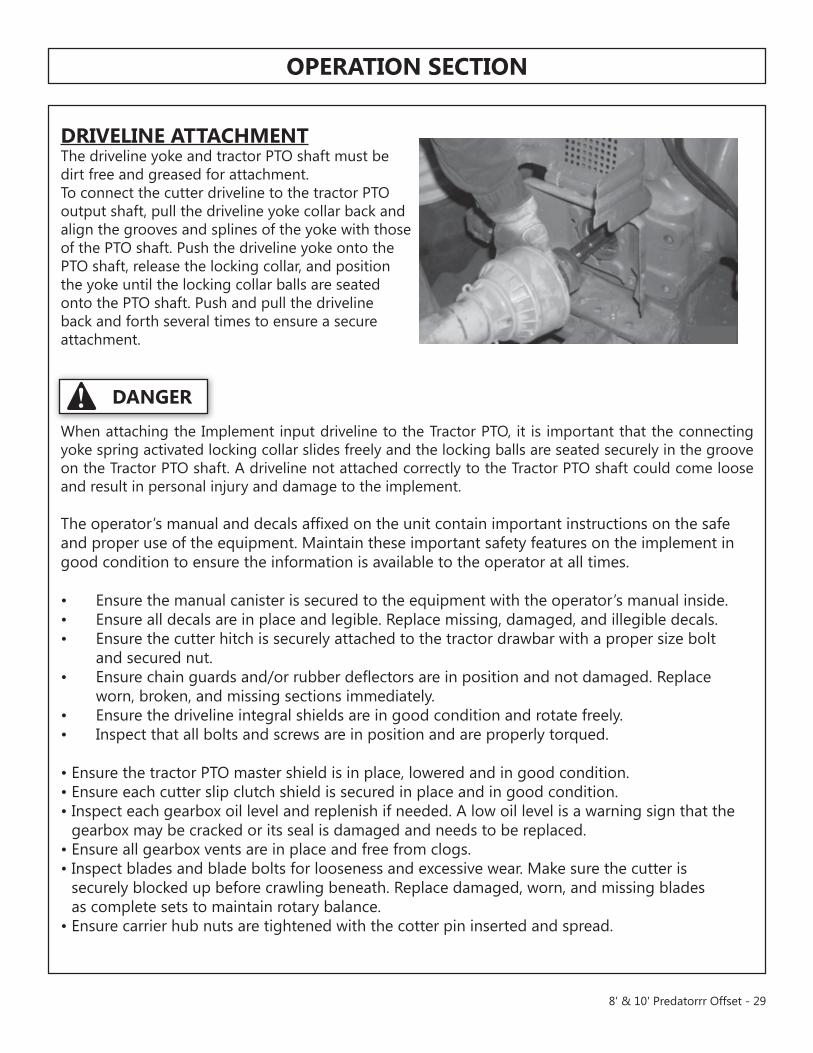
DRIVELInE aTTacHMEnTthe driveline yoke and tractor PtO shaft must bedirt free and greased for attachment.to connect the cutter driveline to the tractor PtOoutput shaft, pull the driveline yoke collar back andalign the grooves and splines of the yoke with thoseof the PtO shaft. Push the driveline yoke onto thePtO shaft, release the locking collar, and positionthe yoke until the locking collar balls are seatedonto the PtO shaft. Push and pull the drivelineback and forth several times to ensure a secureattachment.
When attaching the Implement input driveline to the tractor PtO, it is important that the connecting yoke spring activated locking collar slides freely and the locking balls are seated securely in the groove on the tractor PtO shaft. a driveline not attached correctly to the tractor PtO shaft could come loose and result in personal injury and damage to the implement.
the operator’s manual and decals affixed on the unit contain important instructions on the safe and proper use of the equipment. maintain these important safety features on the implement in good condition to ensure the information is available to the operator at all times.
• ensure the manual canister is secured to the equipment with the operator’s manual inside.• ensure all decals are in place and legible. Replace missing, damaged, and illegible decals. • ensure the cutter hitch is securely attached to the tractor drawbar with a proper size bolt and secured nut.• ensure chain guards and/or rubber deflectors are in position and not damaged. Replace worn, broken, and missing sections immediately.• ensure the driveline integral shields are in good condition and rotate freely.• Inspect that all bolts and screws are in position and are properly torqued.
• ensure the tractor PtO master shield is in place, lowered and in good condition.• ensure each cutter slip clutch shield is secured in place and in good condition.• Inspect each gearbox oil level and replenish if needed. a low oil level is a warning sign that the
gearbox may be cracked or its seal is damaged and needs to be replaced.• ensure all gearbox vents are in place and free from clogs. • Inspect blades and blade bolts for looseness and excessive wear. make sure the cutter is
securely blocked up before crawling beneath. Replace damaged, worn, and missing blades as complete sets to maintain rotary balance.
• ensure carrier hub nuts are tightened with the cotter pin inserted and spread.
DangER
8' & 10' Predatorrr Offset - 29
oPERaTIon SEcTIon
Tractor Pre-operation Inspection/ServiceRefer to the tractor operator’s manual to ensure a complete pre-operation inspection and scheduled service is performed according to the manufacturers recommendations. the followingare some of the items that require daily service and inspection:
• tire condition/air pressure• Wheel lug bolts• Steering linkage• PtO shield• SmV sign is clean and visible• tractor’s lights are clean and functional• tractor Seat belt is in good condition• tractor ROPS is in good condition• ROPS is in the raised position• no tractor oil leaks• Radiator free of debris• engine oil level and condition• engine coolant level and condition• Power brake fluid level• Power steering fluid level• Fuel condition and level• Sufficient lubrication at all lube points• air filter condition
cutter Pre-operation Inspection/ServiceBefore each cutter use, a complete inspection and service is required to ensure the cutter is in a good and safe working condition. Damaged and/or broken parts should be repaired and/or replaced immediately. to ensure the cutter is ready for operation, conduct the following.
the operator’s manual and safety signs affixed on the unit contain important instructions on the safe and proper use of the equipment. maintain these important safety features on the implement in good condition to ensure the information is available to the operator at all times.
• ensure the manual canister is secured to the equipment with the operator’s manual inside.• ensure all safety signs are in place and legible. Replace missing, damaged, and illegible decals.
30 - 8' & 10' Predatorrr Offset
oPERaTIon SEcTIon
cutter Pre-operation Inspection/Service continued• Perform scheduled lubrication as detailed in the maintenance section.• ensure all decals are in place and legible.• ensure the driveline is securely attached to tractor. make sure the driveline yoke locking collar is
securely seated in the grooves of the PtO shaft by pushing and pulling the yoke several times.• ensure deflectors and/or chainguards are in position and not damaged. Replace worn, broken,
and missing pieces. • Inspect all bolts and screws and tighten to the recommended torque.• ensure the driveline integral shield is in good condition and rotates freely.• ensure the driveline slip clutch (if equipped) is properly adjusted. • Inspect the gearbox oil level. a low oil level is a warning sign that the gearbox may be cracked or
its seal is damaged and needs replacement.• ensure the gearbox vent is in place and free from clogs.• Inspect blades and blade bolts for looseness and excessive wear. make sure the cutter is securely
blocked up before crawling beneath. Replace damaged, worn and missing blades as complete sets to maintain rotary balance during operation.
• ensure carrier hub nut is tightened with the cotter pin inserted and spread.
all Safety Shields, Guards and Safety devices should be used and maintained in good working condition. all safety devices should be inspected carefully at least daily for missing or broken components. missing, broken, or worn items must be replaced at once to reduce the possibility of injury or death from thrown objects, entanglement, or blade contact.
DangER
8' & 10' Predatorrr Offset - 31
oPERaTIon SEcTIon
Rotary cutter PRE-oPERaTIon Inspection
Cutter ID#________________ make ____________________Date: ________________ Shift ____________________
Before conducting the inspection, make sure the tractor engine is off, all rotation has stopped and the tractor is in park with the parking brake engaged. Make sure the cutter is resting on the ground or securely blocked up.
the Operator’s manual is in the canister on the cutterall safety decals are in place and legiblethe hitch connection bolts & pins are tightthe cutter deck is clear of cut grass and debrisChain guards/deflectors are in place & in good conditionDriveline/gearbox shields are in good conditionDriveline telescoping members & u-joints are lubricatedDriveline yokes are securely attached to PtO & cutterGearbox mounting bolts are tightGearbox oil is at the proper levelBlade carrier retaining nut is tightBlades are not chipped, cracked or bentBlade bolts are tightWheel lug nuts are tight
Operator’s Signature:
Do noT oPERaTE an UnSaFE TRacToR or cutter
Item condition at Start of Shift
Specific Comments if not O.K.
32 - 8' & 10' Predatorrr Offset
oPERaTIon SEcTIon
Tractor PRE-oPERaTIon Inspection
Cutter ID#________________ make ____________________Date: ________________ Shift ____________________
Before conducting the inspection, make sure the tractor engine is off, all rotation has stopped and the tractor is in park with the parking brake engaged. Make sure the cutter is resting on the ground or securely blocked up.
the flashing lights function properlythe SmV Sign is clean and visiblethe tires are in good condition with proper pressurethe wheel lug bolts are tightthe tractor brakes are in good conditionthe steering linkage is in good conditionthere are no visible oil leaksthe hydraulic controls function properlythe ROPS or ROBS Cab is in good conditionthe seatbelt is in place and in good conditionthe 3-point hitch is in good conditionthe drawbar pins are securely in placethe PtO master shield is in placethe engine oil level is fullthe brake fluid level is fullthe power steering fluid level is fullthe fuel level is adequatethe engine coolant fluid level is fullthe radiator is free of debristhe air filter is in good condition
Operator’s Signature:
Do noT oPERaTE an UnSaFE TRacToR or cutter
Item condition at Start of Shift
Specific Comments if not O.K.
8' & 10' Predatorrr Offset - 33
oPERaTIon SEcTIon
DRIVIng THE TRacToR anD IMPLEMEnT
Safe tractor transport requires the operator possess a thorough knowledge of the model being operated and precautions to take while driving with an attached implement. ensure the tractor has the capacity to handle the weight of the implement and the tractor operating controls are set for safe transport. to ensure safety while driving the tractor with an attached implement, review the following.
the Implement and tractor to pivot violently resulting in loss of steering control, serious injury, or even death.
never allow the Implement to contact obstacles.
transport only at speeds where you can maintain control of the equipment. Serious accidents and injuries can result from operating this equipment at high speeds. understand the tractor and Implement and how it handles before transporting on streets and highways. make sure the tractor steering and brakes are in good condition and operate properly.Before transporting the tractor and Implement, determine the proper transport speeds foryou and the equipment. make sure you abide by the following rules:test the tractor at a slow speed and increase the speed slowly. apply the Brakes smoothly to determine the stopping characteristics of the tractor and Implement. as you increase the speed of the tractor the stopping distance increases.Be aware of the operating conditions. Do not operate the tractor with weak or faulty brakesor worn tires. When operating down a hill or on wet or rain slick roads, the braking distanceincreases: use extreme care and reduce your speed. When operating in traffic always usethe tractor’s flashing warning lights and reduce your speed. Be aware of traffic around youand watch out for the other guy.
10. DRIVING THE TRACTOR AND IMPLEMENTSafe tractor transport requires the operator possess a thorough knowledge of the model being operated andprecautions to take while driving with an attached implement. Ensure the tractor has the capacity to handle theweight of the implement and the tractor operating controls are set for safe transport. To ensure safety whiledriving the tractor with an attached implement, review the following. OPS-U- 0012
This Implement is wider than the Tractor. Be careful when operating or transporting thisequipment to prevent the Implement from running into or striking sign posts, guard rails,concrete abutments or other solid objects. Such an impact could cause the Implement and
Tractor to pivot violently resulting in loss of steering control, serious injury, or even death. Never allow theImplement to contact obstacles. (S3PT-12)
Transport only at speeds where you can maintain control of theequipment. Serious accidents and injuries can result from operating thisequipment at high speeds. Understand the Tractor and Implement and
how it handles before transporting on streets and highways. Make sure the Tractor steeringand brakes are in good condition and operate properly.
Before transporting the Tractor and Implement, determine the proper transport speeds foryou and the equipment. Make sure you abide by the following rules:
• Test the tractor at a slow speed and increase the speed slowly. Apply the Brakes smoothly to determine the stopping characteristics of the Tractor and Implement. As you increase the speed of the Tractor the stopping distance increases. Determine the maximum transport speed not to exceed 20 mph (30 kph) for towing this equipment.
• Test the equipment at a slow speed in turns. Increase the speed through the turn only after you determine that it is safe to operate at a higher speed. Use extreme care and reduce your speed when turning sharply to prevent the tractor and implement from turn-ing over. Determine the maximum safe turning speed for you and this equipment before operating on roads or uneven ground.
• Only transport the Tractor and Implement at the speeds which allow you to properly control the equipment.
Be aware of the operating conditions. Do not operate the Tractor with weak or faulty brakesor worn tires. When operating down a hill or on wet or rain slick roads, the braking distanceincreases: use extreme care and reduce your speed. When operating in traffic always usethe Tractor’s flashing warning lights and reduce your speed. Be aware of traffic around youand watch out for the other guy. (SG-19)
waRnIng
34 - 8' & 10' Predatorrr Offset
oPERaTIon SEcTIon
Inclines and ditches should be approached along a line which is at an angle as shown. this type of path will reduce the possibility of over-collapse of the driveline and resulting damage. If the gradient is so steep that such an approach increases the possibility of a tractor roll-over, select an alternate crossing path.
When operating the tractor and cutter across slopes and inclines, through ditches, and other uneven terrain conditions, it is important to maintain sufficient deck to ground clearance. Blade contact with the ground may cause soil, rocks and other debris to be thrown out from under the cutter resulting in possible injury and/or property damage. Ground contact also produces a severe shock load on the cutter drive and to the cutter blades resulting in possible damage and premature wear.
oPERaTIng THE TRacToR anD IMPLEMEnT
THE oPERaToR MUST coMPLETELy UnDERSTanD How To oPERaTE THE TRacToR anD IMPLEMEnT anD aLL conTRoLS BEFoRE aTTEMPTIng To oPERaTE. the operator must read and understand the Safety and Operation Sections of the implement and tractor operator’s manuals. these manuals must be read and explained to any operator who cannot read. never allow someone to operate the implement and tractor without complete operating instructions.
Before starting any operation, the operator must become familiar with the area to be worked in and any obstacles and hazards contained within to ensure safety to the operator, bystanders, and equipment. Special attention should be paid to foreign debris, rough terrain, steep slopes, and passersby and animals in the area.
extreme care should be taken when operating near loose objects such as gravel, rocks, wire, and other debris. Inspect the area before mowing. Foreign objects should be removed from the site to prevent machine damage and/or bodily injury or even death. any objects that cannot be removed must be clearly marked and carefully avoided by the operator. Stop mowing immediately if blades strike a foreign object. Repair all damage and make certain rotor or blade carrier is balanced before resuming mowing.
Inclines and ditches should be approached along aline which is at an angle as shown. This type ofpath will reduce the possibility of over-collapse ofthe driveline and resulting damage. If the gradientis so steep that such an approach increases thepossibility of a tractor roll-over, select an alternatecrossing path.
When operating the tractor and mower acrossslopes and inclines, through ditches, and otheruneven terrain conditions, it is important to maintainsufficient deck to ground clearance. Blade contactwith the ground may cause soil, rocks and otherdebris to be thrown out from under the mowerresulting in possible injury and/or property damage.Ground contact also produces a severe shock loadon the mower drive and to the mower bladesresulting in possible damage and premature wear.OPS-R-0022
11. OPERATING THE TRACTOR AND IMPLEMENTTHE OPERATOR MUST COMPLETELY UNDERSTAND HOW TO OPERATE THE TRACTOR ANDIMPLEMENT AND ALL CONTROLS BEFORE ATTEMPTING TO OPERATE. The operator must read andunderstand the Safety and Operation Sections of the implement and tractor operator’s manuals. Thesemanuals must be read and explained to any operator who cannot read. Never allow someone to operate theimplement and tractor without complete operating instructions.
Before starting any operation, the operator must become familiar with the area to be worked in and anyobstacles and hazards contained within to ensure safety to the operator, bystanders, and equipment. Specialattention should be paid to foreign debris, rough terrain, steep slopes, and passersby and animals in the area.OPS-U- 0015
Extreme care should be taken when operating near loose objects suchas gravel, rocks, wire, and other debris. Inspect the area beforemowing. Foreign objects should be removed from the site to prevent
machine damage and/or bodily injury or even death. Any objects that cannot be removedmust be clearly marked and carefully avoided by the operator. Stop mowing immediately ifblades strike a foreign object. Repair all damage and make certain rotor or blade carrier isbalanced before resuming mowing. (SGM-5)
waRnIng
8' & 10' Predatorrr Offset - 35
oPERaTIon SEcTIon
Rotary Cutters are capable under adverse conditions of throwing objects for great distances (300 feet or more) and causing serious injury or death. Follow safety messages carefully.
SToP MowIng IF PaSSERSBy aRE wITHIn 100 yaRDS UnLESS:
- Front and Rear Deflectors, Chain Guards, or Bands are installed and in good, workable condition;
-Passersby are outside the existing thrown-object zone;
- all areas have been thoroughly inspected and all foreign material such as rocks, cans, glass, and general debris has been removed.
NOTE: Where there are grass and weeds high enough to hide debris that could be struck by the blades, the area should be: inspected and large debris removed, mowed at an intermediate height, inspected, closely with any remaining debris being removed, and mowed again at desired final height. (This will also reduce power required to mow, reduce wear and tear on the Cutter drivetrain, spread cut material better, eliminate streaking, and make the final cut more uniform).
Engaging the Power Take off (PTo)Before engaging the PtO, make certain that the area is clear of bystanders and passersby. the implement must be completely lowered and the deck positioned at a safe operating height. neVeR engage the PtO with the implement in the raised position.Set the tractor engine speed at approximately 1,000 RPm before engaging the PtO. Shift the PtO control to the on position, and slowly increase the engine speed until the PtO is operating at the rated speed. If you hear unusual noises or see or feel abnormal vibrations, disengage the PtO immediately. Inspect the implement to determine the cause of the noise or vibration and repair the abnormality.
Do not let the Blades turn when the Cutter Deck is raised for any reason, including clearance or for turning. Raising the Cutter deck exposes the Cutting Blades which creates a potentially serious hazard and could cause serious injury or even death from objects thrown from the Blades.
Do not put hands or feet under cutter decks. Blade Contact can result in serious injury or even death. Stay away until all motion has stopped and the decks are securely blocked up.
Rotary Mowers are capable under adverse conditions of throwingobjects for great distances (300 feet or more) and causing serious injuryor death. Follow safety messages carefully.
STOP MOWING IF PASSERSBY ARE WITHIN 100 YARDS UNLESS:
-Front and Rear Deflectors, Chain Guards, or Bands are installed and in good, workablecondition;
-Mower sections or Wings are running close to and parallel to the ground without exposedBlades;
-Passersby are outside the existing thrown-object zone;
-All areas have been thoroughly inspected and all foreign material such as rocks, cans,glass, and general debris has been removed.
NOTE: Where there are grass and weeds high enough to hide debris that could be struckby the blades, the area should be: inspected and large debris removed, mowed at anintermediate height, inspected, closely with any remaining debris being removed, andmowed again at desired final height. (This will also reduce power required to mow, reducewear and tear on the Mower drivetrain, spread cut material better, eliminate streaking, andmake the final cut more uniform). (SRM-1)
11.3 Engaging the Power Take Off (PTO)Before engaging the PTO, make certain that the area is clear of bystanders and passersby. The implementmust be completely lowered and the deck positioned at a safe operating height. NEVER engage the PTO withthe implement in the raised position.
Set the tractor engine speed at approximately 1,000 RPM before engaging the PTO. Shift the PTO control tothe on position, and slowly increase the engine speed until the PTO is operating at the rated speed. If youhear unusual noises or see or feel abnormal vibrations, disengage the PTO immediately. Inspect theimplement to determine the cause of the noise or vibration and repair the abnormality. OPS-U- 0027
Do not let the Blades turn when the Mower Deck is raised for any reason,including clearance or for turning. Raising the Mower deck exposes theCutting Blades which creates a potentially serious hazard and could
cause serious injury or even death from objects thrown from the Blades. (SRM-7)
Do not put hands or feet under mower decks. Blade Contact can resultin serious injury or even death. Stay away until all motion has stoppedand the decks are securely blocked up. (SGM-9)
waRnIng
waRnIng
36 - 8' & 10' Predatorrr Offset
oPERaTIon SEcTIon
many varied objects, such as wire, cable, rope, or chains, can become entangled in the operating parts of the cutter head. these items could then swing outside the housing at greater velocities than the blades. Such a situation is extremely hazardous and could result in serious injury or even death. Inspect the cutting area for such objects before mowing. Remove any like object from the site. never allow the cutting blades to contact such items.
Foreign Debris HazardsBefore mowing, inspect the area to make sure there are no foreign objects that the cutter blades could hit or become entangled with. Remove all foreign objects and debris. If objects are too big to remove, mark them clearly and be sure to prevent the cutter blades from contacting them.
If you hit a solid object or foreign debris, stop the cutter and tractor at once. Immediately idle theengine speed and disengage the PtO. Wait for all cutter rotating motion to stop, then raise the cut-ter and move the tractor and implement off the object. Inspect the area and remove, or mark the location of the debris. Inspect the condition of the cutter and make any needed repairs immediately. make sure the blades are not damaged and the carrier is balanced before resuming operation.
always wear your seat belt securely fastened and only operate the tractor and cutter with the ROPS in the raised position. If the tractor or cutter hits a tree stump, rock, or bump, a sudden movement could throw you off of the seat and under the tractor and/or cutter. the seat belt is your best protec-tion from falling off the tractor and the ROPS provides protection from being crushed during atractor roll-over.
Bystanders/Passersby PrecautionsIf a bystander comes within 300 feet of the tractor while the cutter is being operated, stop the trac-tor at once, idle the engine and disengage the PtO. Do not engage the PtO again until all bystand-ers are well past the 300 foot distance.
8' & 10' Predatorrr Offset - 37
oPERaTIon SEcTIon
PTo RPM and ground SpeedGround speed for mowing will depend upon the height, type, and density of vegetation to be cut.Recommended speed for efficient cutter performance is between 2 and 5 mph. Operate the cutter at its full rated PtO speed to maintain blade speed for a clean cut. Refer to the tractor operator’s manual or the tractor instrument panel for the engine speed and gear to provide the required PtO and desired ground speed. make sure that the cutter is operating at its full rated speed before entering the vegeta-tion to be cut. If it becomes necessary to temporarily regulate engine speed, increase or decrease the throttle gradually.
Ground speed is achieved by transmission gear selection and not by the engine operating speed. the operator may be required to experiment with several gear range combinations to determine the best gear and range which provides the most ideal performance from the cutter and most efficient tractor operation. as the severity of cutting conditions increase, the ground speed should be decreased by selecting a lower gear to maintain the proper operating PtO speed.
Do not exceed the rated PtO speed for the Implement. excessive PtO speeds can cause implement driveline or blade failures resulting in serious injury or death.
mow at the speed that you can safely operate and control the tractor and cutter. Safe mowing speed depends on terrain condition and grass type, density, and height of cut. normal ground speed range is from 2 to 5 mph. use slow mowing speeds when operating on or near steep slopes, ditches, drop-offs, overhead obstructions, power lines, or when debris and foreign objects are to be avoided. operating the cutterOnly operate the cutter from the tractor operator’s seat with the seatbelt securely fastened. the tractor must be equipped with a ROPS in the raised position or a ROPS cab.the cutter is designed to cut vegetation up to 2” in diameter. Sharp blades will produce a cleaner cut and require less power. travel at a speed that allows the cutter sufficient time to cut through the vegetation and maintain the PtO operating speed to prevent overloading the cutter and tractor. Choose a driving pattern that provides the maximum pass length and minimizes turning.under certain conditions, tractor tires may roll some grasses down preventing them from being cut at the same height as the surrounding area. When this occurs, reduce the tractor ground speed while main-taining the operating speed of the cutter. a slower ground speed will permit grasses to at least partially rebound and be cut. taking a partial cut and/or reversing the direction of travel may also help produce a cleaner cut.avoid mowing in the reverse direction when possible. In situations where the cutter must be backed to access areas to be cut, make sure there are no persons or other foreign debris behind the cutter before mowing in reverse. When mowing in reverse, operate the tractor and cutter at a reduced ground speed to ensure tractor and cutter control is maintained.
waRnIng
waRnIng
38 - 8' & 10' Predatorrr Offset
oPERaTIon SEcTIon
Do not mow with two machines in the same area except with Cab tractors with the windows closed.
mow only in conditions where you have clear visibility in daylight or with adequate artificial lighting. never mow in darkness or foggy conditions where you cannot clearly see at least 100 yards in front and to the sides of the tractor and cutter. make sure that you can clearly see and identify passersby, steep slopes, ditches, drop-offs, overhead obstructions, power lines, debris and foreign objects. If you are unable to clearly see these type of items discontinue mowing.
avoid mowing in reverse direction when possible. Check to make sure there are no persons behind the cutter and use extreme care when mowing in reverse. mow only at a slow ground speed where you can safely operate and control the tractor and cutter. never mow an area that you have not inspected and removed debris or foreign material.
Follow these guidelines to reduce the risk of equipment and grass fireswhile operating, servicing, and repairing the Cutter and tractor:
-equip the tractor with a fire extinguisher in an accessible location.
-Do not operate the Cutter on a tractor with an underframe exhaust.
-Do not smoke or have an open flame near the Cutter and tractor.
-Do not drive into burning debris or freshly burnt areas.
- ensure slip clutches are properly adjusted to prevent excessive slippage and plate heating. (When applicable)
-never allow clippings or debris to collect near drivelines, slip clutches, and gearboxes.Periodically shut down the tractor and Cutter and clean clippings and collected debris fromthe cutter deck.
Do not mow with two machines in the same area except with Cab tractors with the windowsclosed. (SGM-11)
Mow only in conditions where you have clear visibility in daylight or with adequate artificiallighting. Never mow in darkness or foggy conditions where you cannot clearly see at least100 yards in front and to the sides of the tractor and mower. Make sure that you can clearly
see and identify passersby, steep slopes, ditches, drop-offs, overhead obstructions, power lines, debris andforeign objects. If you are unable to clearly see these type of items discontinue mowing. (SGM-1)
Avoid mowing in reverse direction when possible. Check to make sure there are nopersons behind the mower and use extreme care when mowing in reverse. Mow only at aslow ground speed where you can safely operate and control the tractor and mower.
Never mow an area that you have not inspected and removed debris or foreign material. (SGM-8)
Follow these guidelines to reduce the risk of equipment and grass fireswhile operating, servicing, and repairing the Mower and Tractor:
-Equip the Tractor with a fire extinguisher in an accesible location.
-Do Not operate the Mower on a Tractor with an underframe exhaust.
-Do Not smoke or have an open flame near the Mower and Tractor.
-Do Not drive into burning debris or freshly burnt areas.
-Ensure slip clutches are properly adjusted to prevent excessive slippage and plate heating.
-Never allow clippings or debris to collect near drivelines, slip clutches, and gearboxes.Periodically shut down the Tractor and Mower and clean clippings and collected debris fromthe mower deck. (SGM-12)
8' & 10' Predatorrr Offset - 39
oPERaTIon SEcTIon
cUTTER SToRagE
Properly preparing and storing the cutter at the end of the season is critical to maintaining its appearance and to help ensure years of dependable service. the following are suggested storage procedures:
• thoroughly clean all debris off the cutter to prevent damage from rotting grass and standing water.
• Lubricate all cutter grease points and fill gearbox oil levels as detailed in the maintenance section.• tighten all bolts and pins to the recommended torque.• Check the cutter for worn and damaged parts. Perform repairs and make replacements
immediately so that the cutter will be ready for use at the start of the next season.• Store the cutter in a clean, dry place with the cutter housing resting securely on blocks or at ground level.• Keep the driveline yoke from sitting in water, dirt and other contaminants.• use spray touch-up where necessary to prevent rust and maintain the appearance of the cutter.
never allow children to play on or around tractor or Implement. Children can slip or fall off the equipment and be injured or killed. Children can cause the Implement to shift or fall crushing themselves or others.
TRanSPoRTIng THE TRacToR anD IMPLEMEnT
Inherent dangers of operating the tractor and implement and the possibility of accidents are not left behind when you finish working in an area. therefore, the operator must employ good judgement and safe operation practices when transporting the tractor and implement between locations. By using good judgement and following safe transport procedures, the possibility of accidents while moving between locations can be substantially minimized.
never allow children or other persons to ride on the tractor or Implement. Falling off can result in serious injury or death.
DangER
DangER
40 - 8' & 10' Predatorrr Offset
oPERaTIon SEcTIon
Transporting on Public Roadways
extreme caution should be used when transporting the tractor and cutter on public roadways. the tractor must be equipped with all required safety warning features including a SmV emblem and flashing warning lights to alert drivers of the tractor’s presence. Remember that roadways are primarily designed for automotive drivers and most drivers will not be looking out for you, therefore, you must look out for them. Check your side view mirrors frequently and remember that vehicles will approach quickly because of the tractor’s slower speed.
Only tow the Implement behind a properly sized and equipped tractor which exceeds the weight of the Implement by at least 20%. DO nOt tow the Implement behind a truck or other type of vehicle.
never allow children or other persons to ride on the tractor or Implement. Falling off can result in serious injury or death.
make certain that the “Slow moving Vehicle” (SmV) sign is installed in such a way as to be clearly visible and legible. When transporting the equipment use the tractor flashing warning lights and follow all local traffic regulations.
the SmV (Slow-moving Vehicle) emblem is universal symbol used to alert drivers of the presence of equipment traveling on roadways at a slow speed. SmV signs are a triangular bright orange with reflective red trim for both easy day and night visibility. make sure the SmV sign is clean and visible from the rear of the unit before transporting the tractor and implement on a public roadway. Replace the SmV emblem if faded, damaged, or no longer reflective.
14.2 Transporting on Public RoadwaysExtreme caution should be used when transporting the tractor and mower on public roadways. The tractormust be equipped with all required safety warning features including a SMV emblem and flashing warninglights to alert drivers of the tractor’s presence. Remember that roadways are primarily designed forautomotive drivers and most drivers will not be looking out for you, therefore, you must look out for them.Check your side view mirrors frequently and remember that vehicles will approach quickly because of thetractor’s slower speed. Be extremely cautious when the piece of equipment that you are towing is wider thanthe tractor tire width and/or extends beyond your lane of the road.
Make sure that a proper size safety tow chain is secured between the tractor and mower before entering apublic road. Secure the center section at a safe transport height by placing additional stroke control spacerson the center axle cylinder and then lower the mower. Secure the mower wings in the raised position with thetransport lock braces. OPS-R-0036
Only tow the Implement behind a properly sized and equipped Tractorwhich exceeds the weight of the Implement by at least 20%. DO NOTtow the Implement behind a truck or other type of vehicle. Never tow the
Implement and another Implement connected in tandem. Never tow the Implement atspeeds over 20 MPH. (STI-6)
Never allow children or other persons to ride on the Tractor or Implement.Falling off can result in serious injury or death. (SG-10)
Make certain that the “Slow Moving Vehicle” (SMV) sign is installed insuch a way as to be clearly visible and legible. When transporting theEquipment use the Tractor flashing warning lights and follow all local
traffic regulations. (SG-6)
The SMV (Slow-Moving Vehicle) emblem isuniversal symbol used to alert drivers of thepresence of equipment traveling on roadways at aslow speed. SMV signs are a triangular brightorange with reflective red trim for both easy day andnight visibility. Make sure the SMV sign is clean andvisible from the rear of the unit before transportingthe tractor and implement on a public roadway.Replace the SMV emblem if faded, damaged, or nolonger reflective. OPS-U- 0020
waRnIng
waRnIng
DangER
8' & 10' Predatorrr Offset - 41
oPERaTIon SEcTIon
42 - 8' & 10' Predatorrr Offset
TRoUBLE PoSSIBLE caUSE PoSSIBLE REMEDy
Excessive Vibration 1. Check gearbox bolts. tighten if loose.
2. Check for loose nuts on blade tighten if loose. holder and blades.
3. Check for bent output shaft. If shaft Replace shaft if bent. is bent, cutter will have excessive vibration.
4. Check to see if blades are free Free blades so they swing. swinging.
5. Check for even wear on each blade Weigh blades. Weight should be tip. Change both blades at the same within 1 oz. always replace both time. blades.
6. Blade broken. Replace the set of blades. 7. Blade carrier bent. Replace carrier.
8. Blade hub not properly seated on tighten shaft nut to 350 torque ft. shaft (it is loose). lbs.
9. new blade or bolts matched with Replace blades or bolts in sets. worn blade or bolts.
Gearbox Overheating 1. Low on lubricant. Fill to overflow plug.
2. Improper type lubricant. Replace with proper lubricant. 3. excessive trash buildup around Remove trash. gearbox.
4. Bearing or gears set up improperly. Consult your dealer.
Uneven Cutting 1. Blades not sharp. Sharpen or replace blades. 2. tractor PtO speed turning less use correct PtO speed and check than 540 RPm. for correct gearbox ratio. See specifications.
3. Cutter not level. See Cutting Height adjustment.
4. tractor tires mashing down grass. Reverse direction of cutting and drive with one tractor tire out of cutter overlap area. Conditions too wet to cut.
5. Ground speed too fast. Reduce ground speed by shifting to a lower gear.
6. Blades locked back. Free blades.
7. Blades riding up due to blade bolt Replace all blade bolt assemblies. wear or loose bolts.
oPERaTIon SEcTIon
8' & 10' Predatorrr Offset - 43
TRoUBLE PoSSIBLE caUSE PoSSIBLE REMEDy
Streaking Conditions 1. Conditions too wet for cutting. allow grass to dry before cutting. Blades unable to cut that part of Slow ground speed of tractor but grass pressed down by tractor tires. keep engine running at full PtO 540 RPm. Cutting lower may help. 2. Dull blades. Sharpen or replace blades.
Blade Bolts 1. Bolts not tightened. tighten bolts to 350 ft. lbs.
Gearbox Noisy Return to authorized modern dealer service department.
3. Shaft rough in oil seal area. Replace or repair shaft.
4. Oil seal installed wrong. Replace seal.
5. Sand in hole in gearbox housing. Replace gearbox housing.
6. Gasket damaged. Replace gasket.
7. Bolts loose. tighten bolts.
Shear Pin Shears Excessively 1. tractor PtO not being run at 540 RPm. Run at 540 RPm.
2. Heavy material. Reduce ground speed. Raise cutting height.
3. not using proper pin Replace only with recommended shear pin.
MaInTEnancE SEcTIonBefore operating your Rotary Cutter, make sure it is properly lubricated and thoroughly inspected. Only a minimum of time and effort is required to regularly lubricate and maintain this machine to provide long life and trouble free operation.
waRnIng: always disengage the PtO before raising the Rotary Cutter for transporting or making adjustments.
LubricationDo not let excess grease collect on or around parts, particularly when operating in sandy areas. the chart gives the frequency of lubrication in hours, based on normal operating conditions. Severe or unusual conditions may require more frequent lubrication.
use an Sae multipurpose, lithium-type grease for all locations shown. Be sure to clean the fitting thoroughly before using grease gun. Daily lubrication of the driveline slip joint is necessary. Failure to maintain proper lubrication will result in damage to u-joints, gearbox, and/or driveshaft.
MaInTEnancE SEcTIon
DRIVELInE LUBRIcaTIon
Grease Fittings are located on the Cross assembly of each u-Joint and on the telescoping tubes. Grease the u-Joint after each 8 hours of use. Do not force grease through the needle Cup assemblies. Grease the telescoping tubes after every 8 hours use. Some PtO-to-Hitch connections may necessitate cutting a hole in the shields to be able to align the Grease Fitting holes for lubrication. Lubricate the shield bearings every 40 hours.
make certain that the Driveline Integral Shields are free to telescope and rotate around theDriveline without binding.
LIFT TyPE DRIVELInE & PULL JacKSHaFT SHIELDSto remove the main inner driveline shield, Remove the locking screws. align the bearing tabs with the cone pockets. Remove the half-guard and remove the bearing ring.
Inspect the driveline shield for worn areas or cracks. If the shield has any dents or cracks, replace the Shield. While the Shields are off, examine the Driveline for signs of abnormal wear, bent or twisted shafts, or cracks in the shafts or tubes. Check to see that the Drivelines telescope easily. If the Drivelines do not telescope properly or show signs of abnormal wear, the shaft should be repaired or replaced.
caUTIon
8' & 10' Predatorrr Offset - 45
MaInTEnancE SEcTIon
SLIP cLUTcHIf a slip clutch is incorporated in the PtO driveline, it is designed to slip, absorb the shock load, and protect the driveline. this clutch has single disc spring with 6 adjusting nuts.after the first hour of operation, the slip clutch should be checked for overheating. after this first check, the slip clutch should be checked weekly or anytime there is overheating. to adjust the disc clutch, tighten the 6 bolts until Belleville Spring is flat and then loosen each of them 2 turns.the slip clutch should be checked periodically and adjusted to compensate for wear. the lining plates are 1/8” thick when new. Replace after 1/32” wear. If the cutter has been idle for an extended period of time, or in wet weather, before operating check to be sure the friction lining plates are not rusted/corroded together. Should this occur refer to the procedure described in the “Seasonal Clutch maintenance” section on the next page.there are two friction lining plates in the slip clutch. these should be checked weekly for oil or grease, wear, and moisture which could cause corrosion on the drive plates.
all Safety Shields, Guards and Safety devices including (but not limited to) - the Deflectors, Chain Guards, Steel Guards, Gearbox Shields, PtO integral shields, and Retractable Door Shields should be used and maintained in good working condition. all safety devices should be inspected carefully at least daily for missing or broken components. missing, broken, or worn items must be
SEaSonaL cLUTcH MaInTEnancEIt is important that the clutches slip when an obstacle or load heavier than the clutch setting is encountered. therefore, if the machine sits outside longer than 30 days and is exposed to rain and/or humid air it is important to make sure that the clutch lining plates are not rusted/corroded together. Before using the cutter use the following procedure to make sure the clutch will slip and give the overload protection required.1. Loosen nuts on springs until the springs are free, yet remain secure on bolts.2. attach cutter to tractor and start the tractor. Set the engine speed at 1200 RPm.3. mark outer plates as shown in Figure mnt-R-0090.4. engage the PtO (approximately one second) and then quickly disengage it. the friction lining
plates should break loose (check the mark).
46 - 8' & 10' Predatorrr Offset
MaInTEnancE SEcTIon
to assemble the main inner driveline shield, grease the yoke groove and inner profile tube. attach the bearing ring in groove with recesses facing profile tube. FIGuRe mnt-0027. Slide on the half shield. turn the cone until it engages correctly. Install locking screws.
cV TyPE DRIVELInE
8' & 10' Predatorrr Offset - 47
MaInTEnancE SEcTIon
BLaDE SERVIcIngInspect blade before each use to determine that they are properly installed and in good condition. Replace any blade that is bent, excessively nicked, worn or has any other damage. Small nicks can be ground out when sharpening. using only original equipment blades on this cutter. they are made of special heat-treated alloy steel. Substitute blades may not meet specification and may dangerous.
Blade Sharpingalways sharpen both blades at same time to maintain balance. Follow original sharpening pattern. always sharpen blades by grinding. DO nOt heat and pound out edge. Do not sharpen blade to a razor edge, but leave a 1/16” blunt edge. Do not sharpen back side of blade.
IMPORTANT: When sharpening blades, grind each blade the same amount to maintain balance. The difference in blade weights should not exceed 1 ounce. Unbalanced blades will cause excessive vibration which can damage gear box bearings. Vibration may also cause structural cracks in cutter housing.
FOLLOW ORIGInaL PatteRn
MAINTAIN cORNER
Never work under equipment support by a hydraulic device because it may drop if the control is actuated (even with the engine stopped) or in the event of hose failure, etc. Always use a secure support for equipment which must be serviced while in the raised position.
48 - 8' & 10' Predatorrr Offset
MaInTEnancE SEcTIon
BLaDE REMoVaLto removed blades for sharpening or replacement, remove the cover plate on deck of cutter near each gearbox. Remove locknut from blade bolt. Inspect lock nut after removal and replace if threads or nylon insert are damaged. always replace nut when replacing bolt. When installing blades, be sure to check blade bolt pivot diameter for wear. Replace bolt if worn more than 1/4 at any point. Install blade bolts with worn side of bolt away from the center of the blade carrier. tighten lock nut to 300 ft. lbs.
avoid personal injury. Blade and/or bade carrier removal should be done only with the tractor engine shut off, key removed, in neutral, parking brake on, PtO disengaged, and the cutter blocked in the raised position. avoid personal injury. Do not work under cutter without support blocks to keep frame from falling.
BLaDE caRRIER REMoVaLRemove cotter pin and loosen slotted nut on gear box shaft. Loosen but do not remove the nut until the blade carrier is loosened. use a suitable two-jaw gear puller to pull carrier tapered gear box shaft. If gear puller is not available use long bar inserted through blade bolt access hole with end against rotor bar. Strike opposite end of bar with sledge hammer. Rotate blade carrier 180 degrees and repeat process.
HaRDwaRECheck nuts, bolts, and other miscellaneous hardware regularly. Loose hardware is easily lost, cause increased wear on parts, and increase the chance of breakdown. Loose hardware creates potential hazards which could result in personal injury to the operator, support personnel and bystanders. use the “torque Chart” below when tightening bolted connections.
the oil level should be checked and maintained at a “full” level. to fill, remove the oil fill plug (1), the overflow plug (2), add oil until oil overflows. Figure 1.
Note: Make sure cutter is level when checking oil in the gearbox.
Note: Failure to remove 1/4” overflow plug may cause overfilling. Overfilling of gearbox will cause pressure to build up and cause oil seals to leak.
TaILwHEEL:
Grease fitting on hub of wheel. Figure 2. Grease after every 4 hours. also, a grease fitting is provided on the tailwheel boom at caster pivot point. Figure 3. Grease after every 4 hours use to provide maximum trouble free service.
HOuSInGOUTpUT cApINpUT cApInPut Gea R, 29tOut Put PInIOn, 15tINpUT SHAfTBea RInG COneBea RInG COneBea RInG CuPBea RInG CuPBea RInG CuPOUTpUT SEALINpUT SEALInPut GaSKetOut Put GaSKetSpAcERSpAcERcOTTERpINCaPSCReW, 3/8" x 1 1/4"CaPSCReW , 1/2" x 1 1/2"FLan Ge nutLOCKWaSHeR, 3/8"LOCKWaSHeR, 1/2"PIPe PLuG, 1/8"PLuG, PReSSuRe ReLIeFRetaIneR RInGHUB-fOR REfERENcE ONLY
ITEM PaRT no. QUanTITy DEScRIPTIon
8' & 10' Predatorrr Offset - 59
401-0325-04 • 8' PULL TYPEPTo SHaFT anD cLUTcH aSSEMBLy
Wheel Hub with Races & StudsBearing Cone (Outside)Bearing Cup (Outside)Bearing Cup (Inside)Bearing Cone (Inside)SealNutStud Spindle, Single WheelDust capBearing adjust nutWashercotter pinGrease ZerkLaminated tire 6000x9airplane tire 25.5 x 8 x 14
for new Modern Manufacturinggalvanized Predatorrr Series Rotary cutter
a. Limited warrantiesmodern manufacturing warrants any new modern manufacturing implement, purchased from an authorized modern manufacturing dealer, to the original non-commercial, state or municipal purchaser ("Purchaser") for a period not to exceed one (1) year from original purchase date, to be free from defects in material and workmanship. Further, the modern manufacturing Galvanized Super Sunshine ("Cutter") rotary cutter will be covered by the Double-Diamond Limited Warranty. this warranty provides a three (3) year limited gearbox warranty and a three (3) year limited "deck rust thru" warranty. painted cutters are covered with a three(3) year limited gearbox warranty only. under these warranties, modern manufacturing's obligation to the original purchaser is limited to the repair or replacement of any parts found to be defective in material or workmanship under normal use and service during the applicable warranty term. Warranty services must be performed by a dealer or service center authorized by modern manufacturing using only new or remanufactured parts or components furnished by modern manufacturing. modern manufacturing reserves the right to inspect any and all parts which are claimed to have been defective in material and workmanship. modern manufacturing makes no warranty as to the design, capability, capacity or suitability for the use of the implement.
B. Limited warranty Service to receive warranty service, the Purchaser must return the Registration and Warranty Card to modern manufacturing within 30 days of original purchase. Purchaser must report claim, in writing, to the authorized modern manufacturing dealer from whom the Purchaser purchased the implement originally or an approved modern manufacturing dealer within 30 days after the Purchaser discovers the circumstance for the basis of the claim. the purchaser (“at his expense”) will be responsible for any service call and/or the return to and from the dealer’s or service cen-ter’s place of business. after examination of claim, if modern manufacturing finds the part(s) or workmanship to be defective, modern manufacturing will repair or replace defective goods or part(s) or reimburse Purchaser for the cost of the part(s) and reasonable labor charges. the choice will be solely decided by modern manufacturing.
c. not covered By warrantythe limited warranty does not cover any goods or part(s) that have been subjected to improper or abnormal use, fire, negligence, abuse, alteration, modification, accident, lack of or improper maintenance, use of wrong oil or lubricants. this limited warranty does not apply to expendable items such as blades, shields, guards, pneumatic tires or any normal maintenance parts or service.the Double-Diamond Limited Gearbox Warranty does not cover wear items such as teeth, chains, sprockets, belts, springs, gearbox lubricant, hydraulic fluid or any other items that in the company’s sole judgement is a wear item.the Double-Diamond Limited “deck rust thru” Warranty does not cover surface rust caused by loss of galvanizing due to external forces such as scrapes, dents, extreme friction and/or wear, deformity due to accidents or abuse.except as provided herein, no employee, agent, Dealer, or other person is authorized to give any warranties of any nature on behalf of Modern Manufacturing.
D. Disclaimer of Implied warranties & consequential Damages to the extent permitted by law, neither modern manufacturing or any other company affiliated with it makes any warranties, representations or promises as to the quality, performance or freedom from defect of the implements covered by this warranty. tHIS InCLuDeS ImPLIeD WaRRantIeS OF meRCHantaBILItY anD FItneSS FOR a PaRtICuLaR PuRPOSe. tO tHe extent aPPLICaBLe, SHaLL Be LImIteD In DuRatIOn tO tHe aPPLICaBLe PeRIOD OF WaRRantY Set FORtH On tHIS PaGe. tHe PuRCHaSeR’ S OnLY RemeDIeS In COnneCtIOn WItH tHe BReaCH OR PeRFORmanCe OF anY WaRRantY On tHe mODeRn manuFaCtuRInG ImPLementS aRe tHOSe Set FORtH On tHIS PaGe. In nO eVent WILL mODeRn manuFaCtuRInG, tHe DeaLeR OR anY COmPanY aFFILIateD WItH mODeRn manuFaCtuRInG Be LIaBLe FOR InCIDentaL OR COnSeQuentIaL DamaGeS. Such incidental and consequential damages shall include but not be limited to: transportation charges other than normal freight charges; cost of installation other than cost approved by modern manufacturing ; duty; taxes; charges for normal service or loss of crops or any other loss of income; rental of substitute equipment, expenses due to loss, damage, detention or delay in the delivery of equipment or parts resulting from acts beyond modern manufacturing’s control.
E. MiscellaneousProper venue for any lawsuits arising from or related to this limited warranty shall be only in Jefferson County, texas.applicable law may provide rights and benefits to the Purchaser in addition to those provided herein.If any provision of this limited warranty shall violate any applicable law and is held to be unenforceable, then the invalidity of such provision shall not invalidate any other provisions herein. modern manufacturing may waive compliance with any of the terms of this limited warranty, but no waiver of any terms shall be deemed to be a waiver of any other term. mail warranty to: modern ag Products, attn: Cutter Warranty, PO Box 790, Beaumont, texas 77701
MODEL____________________________________ SERIAL #____________________________________
DeaLeR____________________________________ Date DeLIVeReD_____________________
DoUBLE-DIaMonD LIMITED waRRanTy
72 - 8' & 10' Predatorrr Offset
all modern ag Products implements carry a non-transferable one-year manufacturing defects warranty, which covers any latent defect in parts and/or workmanship. Our exclusive DOuBLe DIamOnD LImIteD WaRRantY SYStem additionally covers gearboxes and deck rust thru on all galvanized cutters for varying periods of time. See explanation below.
Provides a 3 year limited warranty on gearbox and deck rust thru.galvanized Predatorrr series only.
BLUE DoUBLE DIaMonD
DoUBLE-DIaMonD LIMITED waRRanTy
MODEL____________________________________ SERIAL #____________________________________
DeaLeR____________________________________ Date DeLIVeReD_____________________
DeaLeR’S StamP
maIL tO:
PuRCHaSeRS aDDReSS:
modern, Inc. warrants its products for a period of one year after date of sale by authorized dealer to be free from defects in material and work-manship, and will replace at its factory, any parts that will be returned, with shipping charges prepaid, and when examined by us, will disclose it to be defective. this warranty will not apply to implements or parts that have been subjected to misuse, negligence, accident, or that have been altered or repaired.
1. Parts may not be returned without authorization by modernag Products.2. all products returned under warranty inspection claim must be returned PRePaID to our factory.3. Our obligation under the above warranty is limited to repair or replacement at our factory of any part or parts which modern, Inc. decides to be defective.4. Products or parts that have been examined by modern, Inc. and determined to be improperly operated, damaged by accident or negligence, field repaired or altered, are not covered by this warranty.5. modern, Inc. reserves the right to change our specification and designs at any time.6. this warranty will not obligate modern, Inc. to bear any cost of labor for field replacement, testing, or adjustment.
LIMITED waRRanTy PoLIcy & REgISTRaTIon
DEALER: I hereby certify that:
1. the machine has been correctly assembled in accordance with manufacturers instructions.2. all bolts have been checked and tightened.3. all other pre-delivery checks have been completed as per operators manual.4. Purchaser was given operators manual and instructed in safe and correct usage of machine and on limitation of warranty.5. machine was tested and operates correctly.
PURCHASER: I hereby certify that:
1. the machine is correctly assembled.2. Receipt of the operators manual which I have read and clearly understood.3. I have a clear understanding of the warranty limitations.4. I have a clear understanding on the correct and safe operation of the machine5. that the machine needs regular maintenance as per instructions in operators manual.6. I have a clear understanding on the capacity of this machine and am aware of its limitations.
(On painted cutters, the extended limited warranties only cover gearboxes. The warranties do no cover deck rust thru.)