Textbook 8 – Waste management and recycling 1 8 – Background Material 8 Textbook 8.1 Introduction Purpose of the textbook "Waste management and recycling” This textbook will enable you to analyse the specific waste management system of a company and to improve the logistics of non-hazardous waste, hazardous waste and used oil. It can also be used to check whether a company complies with the waste regulations of its country of operation. The analysis and improvement of a company’s waste management system constitutes an important initial step towards the implementation of a cleaner production strategy. Why is it necessary to review waste legislation if we are only planning to improve logistics? Legislation on waste constitutes the foundation of a company’s waste logistics system. If you are not properly informed about these regulations, you risk building up the waste logistics system incorrectly, thus making wrong investments and having to pay fines for not observing regulations. Benefits of analyzing the waste management system and optimizing logistics Legal compliance You have to make sure that all waste-related regulations are observed. Detailed information on waste quantities and costs You are informed about developments relating to quantities and costs of non-hazardous waste, hazardous waste and waste oil and can take targeted measures to avoid and recycle this waste. Disposal security, optimizing disposal costs A functional waste logistics system ensures that not only re-usable waste, but also hazardous waste, is properly segregated and no longer ends up in the more costly component of residual waste. Consequently, residual waste is reduced along with waste disposal and recycling costs. You pay twice for waste Please note: Avoiding waste is more economical and environmentally friendly than collecting and recycling waste. Waste consists of costly raw materials that have not been transformed into products and for which one pays additional disposal costs. Waste logistics based on legislation Benefits
Transcript
Textbook 8 – Waste management and recycling
1
8 – Background Material
8 Textbook
8.1 Introduction
Purpose of the textbook "Waste management and recycling”
This textbook will enable you to analyse the specific waste management system of a company and to improve the logistics of non-hazardous waste, hazardous waste and used oil. It can also be used to check whether a company complies with the waste regulations of its country of operation.
The analysis and improvement of a company’s waste management system constitutes an important initial step towards the implementation of a cleaner production strategy.
Why is it necessary to review waste legislation if we are only planning to improve logistics?
Legislation on waste constitutes the foundation of a company’s waste logistics system. If you are not properly informed about these regulations, you risk building up the waste logistics system incorrectly, thus making
wrong investments and having to pay fines for not observing regulations.
Benefits of analyzing the waste management system and optimizing logistics
� Legal compliance
You have to make sure that all waste-related regulations are observed.
� Detailed information on waste quantities and costs
You are informed about developments relating to quantities and costs of
non-hazardous waste, hazardous waste and waste oil and can take targeted measures to avoid and recycle this waste.
� Disposal security, optimizing disposal costs
A functional waste logistics system ensures that not only re-usable waste, but also hazardous waste, is properly segregated and no longer ends up in
the more costly component of residual waste. Consequently, residual waste is reduced along with waste disposal and recycling costs.
You pay
twice for waste
Please note:
Avoiding waste is more economical and environmentally friendly than collecting and recycling waste.
Waste consists of costly raw materials that have not been
transformed into products and for which one pays additional disposal costs.
Waste logistics
based on legislation
Benefits
Textbook 8 – Waste management and recycling
2
� Image/motivation
You will be able to motivate the company’s staff because, for many people,
a functional waste segregation system is the best example of an active environmental policy. Moreover, you will contribute to protecting the
environment and economizing on resources.
� Environmental management
A well working waste management system is a precondition for certification
under the EU Eco-Audit Regulation.
� Development of waste disposal sites
Prices for waste disposal will rise in future. Companies that have already
reduced their industrial waste will thus be at an advantage.
Analysing the waste management system and optimizing waste logistics always pays off – in the short and long term!
In addition, this textbook includes brief descriptions of waste recycling technologies in the following chapters:
� Biogas 8.3
� Closing water cycles 8.4
� Composting 8.5
� Energy use of waste 8.6
� Steel recycling 8.7
� Aluminium recycling 8.8
� Copper recycling 8.9
� Plastics recycling 8.10
These chapters, however, can only provide an overview of some important technical and organizational aspects of recycling technologies, since a more detailed description requires more background knowledge. Each chapter
includes a list with additional references and internet links, for further information.
Textbook 8 – Waste management and recycling
3
8.2 Analysis of the waste management system and optimization of logistics
The problem
In many companies, employees in charge do not even know that problems can arise with waste, as they have little or no knowledge of the relevant
waste management legislation, and since thus are not aware of the composition of their residual waste. Who wants to look into waste containers? Or even sort things from waste containers? Let other people do
that job!
In many cases, no suitable container system is used and employees have inadequate or incorrect information on the appropriate segregation of
waste. This results in an excessive amount of re-usable but also hazardous waste in the residual waste.
The solution
Initiate a project “Analysis of the waste management system and optimization of company-specific logistics”. Use the experience gained in many other fields for this project and observe the following procedure to
analyse the waste management system and optimize the company’s logistics:
1. Discuss the project with the management and the environmental team.
2. Familiarize yourself with the relevant waste management legislation.
3. Ensure that the legal requirements for waste management are observed and, if necessary, initiate modifications.
4. Allocate the types of waste produced to the appropriate areas.
5. Collect data on waste volume and disposal costs.
6. Evaluate the company and identify, together with
members of staff, the specific weak points and possible improvements in the company.
7. Discuss the results with the environmental team.
8. Present the results to management.
9. Implement company-specific measures.
The waste situation in
many companies
Textbook 8 – Waste management and recycling
4
1. Discuss the project with the management and the environmental team
The project “Analysis of the waste management system and optimization of company-specific logistics” should be initiated and implemented together
with the environmental team (see Volume 1). Inform the environmental team and the management and make sure that they support the project. Whether you carry out the surveys on your own or in a team will depend on
the size of the company and the existing organizational structure of the company’s waste management system.
2. Familiarize yourself with the relevant waste management
legislation
If you are not yet familiar with the relevant waste management legislation, study it before starting the project. You will learn to use the correct terms
and get a good overview of the applicable laws.
3. Check the legal requirements for waste management – initiate
modifications
Which regulations have already been fulfilled by the company and where is it necessary to take corrective measures? Try to allocate the different types of
waste to their respective areas. Next describe how the company fulfils the legal requirements. This will provide an overview of the various departments of the company in terms of waste generated.
Enter the following details into the general waste management plan and Worksheet 8-1 “Overview of the waste management system”.
Areas of the company (e.g. production, storage, administration, central waste site, workshop, printing shop, etc.);
Allocate identifiers based on existing designations to the different areas
(e.g. production = P, storage = S, office = O, etc.).
4. Allocate the types of waste produced to the appropriate areas
Before examining waste logistics in more detail, establish an overview of the waste arising from the different areas of the company (see Worksheet 8-1 “Overview of the waste management system”).
Divide the company into waste-relevant areas, i.e. places where waste is generated. Mark these places with an abbreviation (P = production, S = storage, A = administrative area, W = workshop, CW = central waste point). Collect information on procedures and activities in the individual areas. Thus you get an initial overview of the waste-relevant areas in the
company and on the types of waste generated.
Types of waste generated in
various areas of the company
Survey of waste volume and
disposal costs
Textbook 8 – Waste management and recycling
5
5. Collect data on waste volumes and disposal costs
Next, using Worksheet 8-2, survey the quantities of waste actually
produced in the company as well as disposal costs and possible revenue from different types of waste.
Recording waste-related data will also help you to identify the build up of waste volumes. Examine the data of the past two years before your company visit in order to have all the necessary information on recycling
fees, disposal costs and revenue from different types of waste.
6. Identify weak points and possible improvements
Visit the company and inform all the employees in the various departments
about the project. Discuss the available data with the responsible persons and collect missing data. Include cleaning staff (also from external cleaning companies) in the data collection process. The objective of the company
visit is to identify and document the specific weak points of a company and discuss possible improvements with the people involved.
Take photographs of the current waste logistics system as well as the waste composition in general and use these photographs in your presentation to management. This will help you to ensure management’s
support for subsequent implementation of suggested measures.
Look into the waste containers and estimate the percentage of reusable waste. Note whether it contains any hazardous waste. If the company has
a waste compressing machine, and it is impossible to look inside, instead lock the waste compression machine and check the waste deposited during the course of a day, or inspect the waste dumped at the waste disposal
site.
During the company visit, educate staff about the types of waste that have to be segregated by law and invite them to suggest measures for
improvement. (Container systems, key colours for different types of waste, labels and signs, decentralized collection points, adaptation of the central
collection point, etc.)
Use the waste segregation guide from the Examples section (Example 8-4) as a model and draw up a specific solution for the company. Find out if the
staff were educated on waste segregation and consider how this knowledge could be incorporated at this early stage. Name waste managers for specific areas of the company.
The waste managers should be committed to environmental issues. They are important partners who will ensure that waste is properly segregated and that staff is informed about waste-related matters.
Company
visit
Textbook 8 – Waste management and recycling
6
7. Discuss the results with the environmental team
Present the results of the waste analysis at the next meeting of the
environmental team. Indicate what has to be done to comply with the legal requirements and which options are available for improving the company’s
logistical system for non-hazardous and hazardous waste. Next, decide with the team what options should be implemented by the company.
After that, request quotations for container systems, the installation of waste
collection points, waste presses or other waste treatment equipment and assess the economic and environmental impact of the planned measures. Negotiate new terms with the disposal company and enquire whether
container systems can be provided free of charge.
8. Present the results to management
Inform management about the specific weak points of the company’s waste
logistics and suggest improvements with detailed information on the economic and environmental impact of the improvements. In many projects
it has proven to be very effective to present slides of the current situation in the company and positive examples from other companies.
Once you have obtained management’s approval for the planned measures,
secure their support for implementation of the planned measures and invite them to set a good example. Inform management about the people appointed as waste managers in each area of the company.
9. Implement company-specific measures
Introduce the necessary measures (order, install and customize waste collection points, design informational material, etc.) Once the preparations
have been completed and the collection systems have arrived, combine the installation of the new containers with a training session.
Since the company’s waste management system should be supported by
everyone, it is important to inform the staff and motivate them to separate waste correctly. For this purpose, a company waste segregation guide is a
very helpful tool. You can find company-specific examples and a waste segregation guide in the Examples section of Volume 8.
When drawing up the guide, ensure that it contains the types of waste
generated in the company. Design a clear and attractive guide. You could, for example, assign the colour of the respective waste containers to each type of waste. This makes it much easier for staff to allocate waste to the
correct category. Indicate a contact person in the event that an employee is uncertain about the correct segregation of waste.
Don’t forget to inform and instruct the company’s cleaning staff or cleaners
from external firms. Furthermore include employees in charge of repair, servicing and building maintenance, as they are particularly important for the implementation the project.
Presentation
of results
Company waste
separation
guide
Textbook 8 – Waste management and recycling
7
8.3 An introduction to biogas
Biogas is generated when bacteria degrade biological material in the absence of oxygen, in a process known as anaerobic digestion (AD). Anaerobic digestion is basically a simple process carried out in a number of steps that can use almost any organic material as a substrate. It occurs in digestive systems, marshes, waste disposal sites, septic tanks and the Arctic Tundra. Humans tend to make the process as complicated as possible by trying to improve on nature using complex machines, but a simple approach is still possible. As shown in the figure on the next page, AD occurs through the symbiotic action of a complex consortium of bacteria. Biogas is generated solely through the activity of bacteria, unlike composting in which fungi and other creatures are also involved in the degradation process of biological material.
It tends to occur naturally wherever high concentrations of wet organic matter accumulate, most commonly in the bottom sediments of lakes and ponds, in swamps, peat bogs, intestines of animals and in the anaerobic interiors of waste disposal sites.
Biogas is a mixture of methane (also known as marsh gas or natural gas), carbon dioxide and numerous trace elements. AD can take place over a wide temperature range from 4 to more than 100 °C and a variety of moisture contents from around 60% to more than 99%. Conventional anaerobic digesters are commonly designed to operate either between 35 and 40 oC or in the range between 52 and 57 oC. There are two reasons for these high temperatures. First, higher temperatures increase output for a given digester capacity, and second they increase the destruction of pathogens present in raw manure.
8.3.1 Applications of anaerobic digestion
Farm-based facilities are perhaps the most common application of anaerobic digestion. Six to eight million family-sized, low-technology digesters are used to provide biogas for cooking and lighting fuels with varying degrees of success. In China and India there is a trend towards using larger, more sophisticated systems with better process control to generate electricity.
In Europe AD facilities are especially used for the treatment of farm, industrial and municipal waste. The treatment of industrial wastewater is widespread in Europe, but also in South America where vinasse, the by-product of sugar cane-based ethanol production, is treated. AD can be used as a pre-treatment step in order to lower sludge disposal costs,
control odours and reduce the cost of final treatment at a municipal wastewater treatment facility.
Textbook 8 – Waste management and recycling
8
8.3.2 Benefits of anaerobic digestion
Economic benefits:
� More cost-effective than other treatment options from a life-cycle perspective.
Energy benefits:
� Net energy producing process (75 – 150 kWh of electricity per tonne of municipal solid waste) instead of the energy-consuming
composting process;
� High-quality renewable fuel.
Waste treatment benefits:
� Requires less land than aerobic composting or landfilling;
� Reduces disposal waste volume and mass to be landfilled.
Environmental benefits:
� Reduces significantly carbon dioxide and methane emissions;
� Eliminates odours;
� Produces a sanitized compost and nutrient-rich fertilizer;
Textbook 8 – Waste management and recycling
9
8.3.3 Factors for success:
� Local environmental regulations;
� Simple design for farm-based digesters;
� Cogeneration with hot water to feed into specifically built district
heating systems.
8.3.4 Process examples
In the following subsection a number of processes are described:
a) The BTA process
The BTA-Process was developed to transform organic waste (OFMSW –
organic fraction of municipal solid waste) from households, commercial and agricultural enterprises into high-grade biogas and valuable compost.
The following feedstock can be used:
� Organic components of municipal solid waste (mixed waste);
� Separated organic waste from households (e.g. kitchen leftovers);
� Food waste from restaurants, canteens and markets;
� Waste from food processing industries;
� Waste from slaughterhouses (e.g. rumen content);
� Waste from agriculture (e.g. manure);
� Sewage sludge as well as the filtered fraction from sewage plants;
� Residual waste – environmentally cautious deposition of residual waste requires reduction of the organic portion of the waste so that no further chemical or biological reaction is likely to occur in the waste disposal
site. This can be achieved with the BTA-Process.
Results:
� Substantial reduction of the waste volume;
� Environmentally benign treatment of waste;
� Maximum energy recovery;
� Reduction of CO2 emissions;
� Production of high-grade compost.
Textbook 8 – Waste management and recycling
10
The process consists of two major steps: Mechanical wet pre-treatment and biological conversion. In the waste-pulper the feedstock is mixed with
recirculated process water. Contaminants such as plastics, textiles, stones and metals are separated by means of a rake and a heavy fraction trap. A
thick pumpable suspension (pulp) is produced which can be easily handled and digested. An optional but essential further component of the process is the grit-removal system which separates the remaining finer materials such
as sand, small stones and glass splinters by passing the pulp through a hydrocyclone. This increasingly protects the plant from abrasion.
Methods
Depending on the plant capacity and the kind of energy and compost used, various methods of biological conversion exist. In the one-stage digestion, the produced pulp is fermented within one single step in a
mixed fermentation reactor. This method allows the BTA technology to be applied in comparatively small, decentralized waste management units.
Existing digesters (for example at a sewage plant or agricultural biogas plants) can be used thus reducing capital and operational costs.
For plants with a capacity of more than 50,000 tonnes per year, multi-stage digestion was developed; where the pulp is separated into solid mass and liquid by a dewatering aggregate. The liquid, already containing dissolved organic components, is directly pumped into a methane reactor and remains there for two days for methanization. The dewatered solid material, still containing undissolved organic components, is once again
mixed with water and fed into a hydrolysis reactor. After four days the mass is dewatered again and the liquid piped into the methane reactor.
Textbook 8 – Waste management and recycling
11
By distributing the degradation process to different reactors (acidification, hydrolysis and methanization) it is ensured that all groups of micro-organisms benefit from optimal growth conditions. This allows a rapid and extended degradation of the organic materials resulting in a high yield of biogas. Within only a few days 60 – 80% of the organic substances are
converted into biogas.
As a further variation for plants with medium capacity, the two-stage digestion is available which is based on the multi-stage concept but without
a solid/liquid separation. The pulp is fed into a mixed hydrolysis reactor which is connected to a stirred tank fermentation reactor. To enable optimal hydrolysis conditions, a fraction of the fermentation reactor content
is fed back into the hydrolysis reactor.
For the treatment of food waste an additional sanitation step can be integrated. All the processes mentioned above have a low water demand,
as the water contained in the waste is recirculated. Excess water is discharged into a sewage plant.
Advantages of the process:
• Wide spectrum of applications (also suitable for waste which is difficult
to compost – e.g. waste with a high moisture content);
• High level of flexibility as the waste composition can vary;
• Effective, automatic selection of contaminants (no sorting by hand);
• High level of safety at work (fully enclosed, automated process);
• Compact, space-saving construction;
Textbook 8 – Waste management and recycling
12
• No unpleasant smell (enclosed process);
• Highly safe to dispose due to redundant components;
• Economic efficiency;
• Highly adaptable to customer needs and environmental requirements.
Products
The final products of the process are biogas and compost. Biogas contains 60 – 65% methane. Due to its high heating value, this gas is an effective
source of energy with a large range of applications. The biogas produced surpasses by far the energy demand of the plant itself. Therefore the surplus can be converted into electricity and heat, which is then fed into a
public network. After a short aerobic treatment (one to three weeks) the anaerobic compost is crops-compatible. The stable, crumbly structure favours the growth of roots as well as the aeration of the soil and is therefore superior to peat and garden compost. Due to its structure, its high percentage of organic substance, its low heavy metal and salt content, and its balanced content of nutrients, BTA compost has a large range of agricultural and horticultural applications.
b) The 2B process Feedstock
The biomass feedstock used in the 2B process includes low value plant
material which is soft, not woody and succulent. Examples are grass (in a wide range of qualities), silaged grass, sugar cane bagasse, residues from vegetable processing and spent grain from breweries.
The first commercial grass plant was commissioned in September 2001 and is located in Schaffhausen, Switzerland,. The first commercial spent grain plant was installed and commissioned in 2002.
The potential of this specific biomass as raw material for the generation of value added products can be estimated by answering the following questions:
1. What are the costs (or negative costs/disposal fees) of potential biomass feedstock?
2. How many tonnes per year are available?
3. Is the raw material seasonally available and, if so, where can it be stored?
Process
The main process steps of this technology comprise of pre-treatment and fractionation of wet biomass, separation of fibres and protein, and
production of an energy carrier. No chemicals are added and no solid waste is produced.
Textbook 8 – Waste management and recycling
13
For the production of biogas the liquid stream is fed into an Upflow Anaerobic Sludge Bed (UASB) reactor after the separation of the fibres
from the protein. For the production of ethanol the non-crystalline cellulosic fibres are converted into monomeric sugars in an enzymatic hydrolysis
process. These sugars are simultaneously transformed into ethanol using conventional yeast in an SSF process (Simultaneous Saccharification and Fermentation). Cellulase enzymes required for the saccharification are
produced using a Trichoderma strain with grass as part of the growth media.
The implementation of ethanol production on a large scale requires the
enhancement of the enzyme production technology. Both production methods have been successfully tested in 2B's pilot plant situated in Märwil, Switzerland, at a raw material feed rate of up to 5 wet tonnes per
hour. The equipment installed at this site includes alternative feeding systems, a continuous pressurized steam cooker with expansion and
cooling of the raw material discharge, fermentation vessels, an enzyme and yeast inoculum line, fractionation, fibre separation, pasteurizers, a decanter, separation equipment, various buffer tanks, a continuous
distillation column, a steam generation unit, driers and others.
2B's extensive background in biomass processing technology results in flexibility with respect to raw materials and end products.
Deublein, Dieter, Steinhauser, Angelika: Biogas from Waste and Renewable
Resources – An Introduction. Wiley-VCH, Weinheim, 2008
Companies
AAT - BIOGAS TECHNOLOGY http://www.aat-biogas.at/en/index.php Activities: Produces suitable gas holders for all fields of activity
Jenbacher AG http://www.ge-energy.com/prod_serv/products/recip_engines/en/index.htm
Activities: Develops and manufactures highly efficient, environmentally friendly gas engines with rated outputs from 300 kW to 3,000 kW. 2B AG, CH-8600 Dübendorf http://swisshosting.com/2bio/indexen.html Activities: Biorefinery: biogas, protein and fibres from grass
In many regions water has become a scarce resource. Measures to reduce water consumption are therefore undertaken not only for economic reasons but also for the mere survival of companies. The long-term objective of research and development in this field is the implementation of zero wastewater technologies.
Closed water cycles require a technology which enables the closing process by adding or extracting energy or special substances (metals, acids, etc.). In many companies closing water cycles is the first step towards the introduction of technologies for the recovery of resources.
Water cycles are mostly divided into modules:
Discontinuous procedure: All modules are connected in parallel. The concentrate is returned to the starting point and passes the same modules again.
Continuous procedure: The sets of modules are connected in series. The different sets themselves consist of modules connected in parallel. The concentrate passes one set after the other and each set consists of a declining number of modules.
8.4.1 Technologies
a) Membranes
Membranes can be considered as filters as they separate different components. At least one component passes the membrane whereas the others are held back. In contrast to normal filters, membranes can separate substances at molecular level.
In order to choose the material for the membrane you need to know the pH-value and the temperature of the wastewater:
- Cellulose acetate for pH 2 – 7.5 and about 15 oC;
- Polyamide membranes for pH 4 – 11.
Different types of modules:
- Pipe module (membrane inside, often used for concentrating substances);
- Tube module (membrane outside, more sensitive to colloids and easier to clean and replace);
- Slab-built modules.
Textbook 8 – Waste management and recycling
16
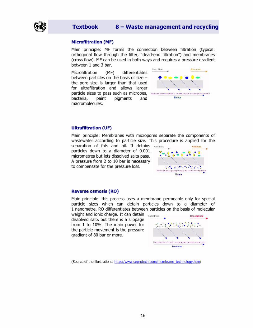
Microfiltration (MF)
Main principle: MF forms the connection between filtration (typical:
orthogonal flow through the filter, “dead-end filtration”) and membranes (cross flow). MF can be used in both ways and requires a pressure gradient
between 1 and 3 bar.
Microfiltration (MF) differentiates between particles on the basis of size –
the pore size is larger than that used for ultrafiltration and allows larger particle sizes to pass such as microbes,
bacteria, paint pigments and macromolecules.
Ultrafiltration (UF)
Main principle: Membranes with micropores separate the components of wastewater according to particle size. This procedure is applied for the separation of fats and oil. It detains particles down to a diameter of 0.001
micrometres but lets dissolved salts pass. A pressure from 2 to 10 bar is necessary to compensate for the pressure loss.
Reverse osmosis (RO)
Main principle: this process uses a membrane permeable only for special particle sizes which can detain particles down to a diameter of 1 nanometre. RO differentiates between particles on the basis of molecular
weight and ionic charge. It can detain dissolved salts but there is a slippage from 1 to 10%. The main power for the particle movement is the pressure gradient of 80 bar or more.
(Source of the illustrations: http://www.seprotech.com/membrane_technology.htm)
Textbook 8 – Waste management and recycling
17
Application MF UF RO Industrial sector
Process and circulation water treatment
X X X Metal processing
Electrical and electronic industry
Food processing
Pharmaceutical industry
Chemical industry
Paper and pulp industry
Ceramics industry
Textile industry, laundries
Water suppliers
Hospitals
Petrol stations
Cleaning and concentration of substances
X Metal processing
Food processing
Pharmaceutical industry
Treatment of oil/water
emulsions
X Environmental engineering
Petrol stations
Machine construction
Concentration of
bases/acids
X Chemical industry
Treatment of rinsing water X Metal processing
b) Evaporators
Main principle: Concentrating the substances contained in the wastewater through vaporization. Non-volatile components are concentrated. The required heat is applied mostly under vacuum (0.2 bar).
The construction of the vaporizer depends on the characteristics of the non-volatile components:
- Circular vaporizer: Circulation through heated pipes. A high flow rate can avoid incrustations in the pipes;
- Thin-layer vaporizer: Due to gravity wastewater flows top down on a heated surface as a thin film;
- Submerged burning evaporator: A pipe is submerged into the wastewater at a level of 30 – 50 cm; hot flue gas is introduced into the water through small slots at the end of the pipe. In this way heat is directly transferred but the strain on the materials is rather high.
Textbook 8 – Waste management and recycling
18
Applications:
- Food industry (residues can be partly used as animal feed);
- Concentrating galvanic rinsing water after a reverse osmosis module;
- Splitting of emulsions.
c) Ion exchange
Main principle: physical-chemical process based on the ability of particular
substances (mostly resin) to absorb special ions from the liquid and in return to emit the same amount of ions. It is used to concentrate microelements (only for concentrations of less than 2 g/l).
A membrane module keeps away oils, emulsive components and halogenated hydrocarbons from the actual ion exchange. Ion exchange can only be used as part of a bigger wastewater treatment process because
most of the discharged concentrates need special treatment.
Application for:
- Electroplating wastewater;
- Softening/demineralization of water;
- Regeneration of process baths;
- Reuse of cleaning/rinsing water.
8.4.2 Case studies for different industrial sectors
As mentioned previously, new combinations of ion-exchange membranes, vaporizers, etc. are used at different stages to close water cycles.
a) Metal processing: surface treatment
Removal of the wax films applied to protect cars during transport
The wax film applied for protection during transport is often removed using
vapour and detergents. Due to emulsifying processes, these components are difficult to separate. The wax components can only be removed from the wastewater through preliminary purification followed by treatment in
the municipal sewage plant. This process produces a considerable amount of sludge and causes high volatility of water (20%) and solvents (40%).
With more recent methods, the formation of emulsions is prevented by
anticipating the separation of wax and detergents. This requires special detergents that do not contain aromatic hydrocarbons. The detergents and the water/wax-conglomerate are split up by an oil-mist separator on to the
basis of their different densities. Special filters mechanically separate wax from water thus reducing hazardous waste by 90%. As a last step of this nearly effluent-free production process, the water is treated with ozone.
Textbook 8 – Waste management and recycling
19
Painting
The painting process is carried out in closed cabins where the humid air
washes out the overspray. The paint coagulates and is separated from the water flow. The treatment of the wastewater depends on the chemical
composition of the paint. A certain amount can be concentrated through the application of a voltage, but the ultrafiltration process has become increasingly common. The water quality can be improved by means of a
multilevel plant. At the Daimler-Chrysler plant in Sindelfingen, for instance, a combination of ultrafiltration with reverse osmosis is used to desalinate water.
The pay back period of investments in recycling technologies for paint is between one and three years.
Module
Permeate
Ceramic membrane
Circulation pump
Function diagram
Process design
Permeate
Automatic permeate backwashing
Ceramic
membrane
Concentrate Working pressure
Medium
Medium supply
Working tank
Textbook 8 – Waste management and recycling
20
Ultrafiltration in a car repair shop
In a car repair shop oily motor parts are regularly cleaned in a closed
machine using an aqueous alkaline solution. Every two to three weeks the washing solution (2,000 litres) has to be changed and disposed of as
hazardous oily waste (see also in the Examples section of Volume 1).
A new ultrafiltration unit continuously filters the solution by means of a ceramic membrane and removes the oil. In this way the washing solution
can be used seven times longer than before. The cost of washing agents, water, and the treatment of hazardous waste was reduced by 75% to 80%. This investment of about EUR 11,000 has a pay back period of about
two years.
b) Food processing
The wastewater generated in the food processing industry in most cases
contains biodegradable substances. The main problem, however, is that water required for washing should have the same quality as that of
drinking water.
Meat processing
Nowadays wastewater is often pre-treated in a mechanical-physical unit
(e.g. grease separator) before it is cleaned in a municipal sewage plant. This process can be improved by an additional biological membrane. Non-biodegradable substances are eliminated afterwards by means of a
standard membrane.
The membranes used in reverse osmosis and nanofiltration technologies build a barrier for bacteria and viruses. To ensure the sterility of the
washing water it should be treated with ultraviolet radiation or ozone.
Brewery: Cold sterilization process
To guarantee a specific shelf life, beer has to be pasteurized before being
bottled. Therefore beer is usually heated to 60 °C causing a change in taste and resulting in high energy consumption.
This can be avoided through cold sterilization, a microfiltration process with 14 modules. An Austrian brewery saved more than 5,200 MWh of energy and 21,000 m3 of water. In addition, wastewater treatment costs were
significantly cut down on account of the annual COD reduction by 42 tonnes.
Textbook 8 – Waste management and recycling
21
8.4.3 References
Companies
Neuhold Environmental Technology http://www.neuhold-envirotec.at/, Activities: Leading Austrian company in the fields of water, wastewater and solid
waste treatment Andritz AG http://www.andritz.com/, Activities: Wastewater treatment, Austria
Techform Engineering http://www.techform.ch/,
Activities: Developing and supplying up-to-date technologies for the recycling and treatment of solid and liquid waste, Switzerland
Ecoling and Partner AG http://www.ecoling.ch/,
Activities: Environmental engineering , energy technology, planning, consultancy, Switzerland
ENVIRO-CHEMIE http://www.enviro-chemie.com/,
Activities: Specialized in the fields of water chemistry, membrane technology and in the treatment of radioactive wastewater
IONICS http://www.ionics.com,
Activities: Manufacturer and seller of membranes and related equipment for the purification, concentration, treatment and analysis of water and wastewater
GE Water Technologies http://www.gewater.com/library/tp/index.jsp, Activities: Offers products and services related to water and industrial process
treatments.
Textbook 8 – Waste management and recycling
22
8.5 Composting
Composting is the decomposition of organic waste producing CO2, water and mature, less active waste. Organic waste is a major fraction of the waste stream. Every year households generate considerable amounts of organic waste and, in view of landfill diversion targets, composting is an attractive alternative for dealing with this waste. The composting process is currently viewed primarily as a waste management method to stabilize organic waste, such as manure, yard trimmings, municipal biosolids and organic urban waste. The stabilized end product (compost) is widely used as soil fertilizer to improve soil structure, provide plant nutrients and facilitate the revegetation of disturbed or eroded soil.
Within the past few years, laboratory, greenhouse and pilot research has shown that the composting process and the use of mature compost also provide an inexpensive and technologically straightforward solution for managing hazardous industrial waste streams (solid, air or liquid) and for remediating soil contaminated with toxic organic compounds (such as solvents and pesticides) and inorganic compounds (such as toxic metals).
8.5.1 The composting process
There are two fundamental types of composting: Aerobic and anaerobic composting. Aerobic composting is the decomposition of organic waste in the presence of oxygen (air). Products from this process include CO2, NH3, water and heat. It can be used to treat any type of organic waste but effective composting requires the right blend of ingredients and conditions. These conditions include moisture content of around 50% and carbon to nitrogen ratios (C/N) of 30:1. Any significant variation inhibits the
degradation process. Generally wood and paper are major sources of carbon while sewage sludge and food waste provide nitrogen. To ensure an adequate supply of oxygen throughout the composting process, ventilation
of the waste, either forced or passive, is essential.
Anaerobic composting is the decomposition of organic waste in the absence of O2, producing methane (CH4), CO2, NH3 and trace amounts of other gases and organic acids. Anaerobic composting was traditionally used to compost animal manure and human sewage sludge but recently it has been frequently used for the treatment of municipal solid waste (MSW) and green waste.
Textbook 8 – Waste management and recycling
23
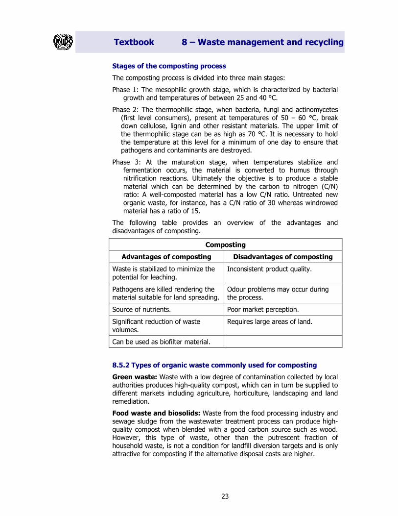
Stages of the composting process
The composting process is divided into three main stages:
Phase 1: The mesophilic growth stage, which is characterized by bacterial growth and temperatures of between 25 and 40 °C.
Phase 2: The thermophilic stage, when bacteria, fungi and actinomycetes (first level consumers), present at temperatures of 50 – 60 °C, break down cellulose, lignin and other resistant materials. The upper limit of
the thermophilic stage can be as high as 70 °C. It is necessary to hold the temperature at this level for a minimum of one day to ensure that pathogens and contaminants are destroyed.
Phase 3: At the maturation stage, when temperatures stabilize and fermentation occurs, the material is converted to humus through nitrification reactions. Ultimately the objective is to produce a stable
material which can be determined by the carbon to nitrogen (C/N) ratio: A well-composted material has a low C/N ratio. Untreated new
organic waste, for instance, has a C/N ratio of 30 whereas windrowed material has a ratio of 15.
The following table provides an overview of the advantages and
disadvantages of composting.
Composting
Advantages of composting Disadvantages of composting
Waste is stabilized to minimize the
potential for leaching.
Inconsistent product quality.
Pathogens are killed rendering the material suitable for land spreading.
Odour problems may occur during the process.
Source of nutrients. Poor market perception.
Significant reduction of waste
volumes.
Requires large areas of land.
Can be used as biofilter material.
8.5.2 Types of organic waste commonly used for composting
Green waste: Waste with a low degree of contamination collected by local authorities produces high-quality compost, which can in turn be supplied to different markets including agriculture, horticulture, landscaping and land remediation.
Food waste and biosolids: Waste from the food processing industry and sewage sludge from the wastewater treatment process can produce high-quality compost when blended with a good carbon source such as wood. However, this type of waste, other than the putrescent fraction of household waste, is not a condition for landfill diversion targets and is only attractive for composting if the alternative disposal costs are higher.
Textbook 8 – Waste management and recycling
24
Municipal solid waste: Unseparated waste from the household waste stream is composted. Shredding of this waste or mixing with sewage
sludge may take place together with screening of the final product.
Composting is an attractive method for treatment of waste because it
involves simple, low cost technology although processing methods can be used to accelerate and improve the composting process. It is a traditional procedure and therefore unlikely to meet significant public opposition
during the planning stage. During the composting process almost one third of the weight is transformed into CO2 and water whereas the remaining compost material can be used to improve the soil structure.
Different types of organic waste streams emanate from gardens, households, commercial establishments, grocery stores, farms and sewage treatment facilities. Each organic stream can be processed differently, and
at appropriate points various organic waste streams can be combined to produce a variety of composts with different properties.
8.5.3 Types of composting
a) Home composting
Any form of home composting carried out by the householder is very beneficial to local authorities. This prevents the waste from entering the
waste stream in the first instance. A survey carried out by the Strathspey Waste Action Network (SWAN) showed that home composting can divert 15% of the household waste fraction. Active composting of food waste
combined with green waste could push this percentage further to 30%. However, while home composting may seem an attractive option it has some difficulties.
Cost of bins: At a price of EUR 30 to 50 each, the bins represent a significant investment, therefore local authorities often provide bins at subsidized prices in the framework of home composting programmes.
Public participation: It is uncertain whether public participation will continue for an extended period of time.
Textbook 8 – Waste management and recycling
25
Home composting functions well where the householder actively utilizes the composted material in his garden. Nonetheless, in some areas, home
composting is an important method for reducing the waste collected by local authorities.
b) Centralized aerobic composting
In order to meet the targets for organic waste diversion, local authorities need to examine composting operations that will divert several thousand
tonnes of waste every year. The different types of composting processes vary significantly, however, we can basically distinguish between two systems:
In open processes, e.g. windrow systems, the composting process takes place at the core of the waste where temperatures can be maintained;
In vessel systems an acceleration of the thermophilic phase shortens
composting time.
c) Anaerobic composting
An alternative to aerobic composting is a system combining anaerobic and aerobic composting developed by Steinmüller Valorga in France and Germany. The system is specifically designed to compost organic MSW and sewage sludge. The first anaerobic stage treats waste with 25 – 35% of
solid content to which some water is added. Waste is first separated to remove uncompostable items, then loaded into the reactor where the solid waste is transformed into liquid through hydrolysis. Biogas is produced
during the process in this same reactor thus allowing biological activity to proceed undisturbed.
Since the system is completely enclosed, gas is collected and piped directly
to an electrical generator. Biogas produced during the process is pumped into the digester from the base at high pressure and is thereby mixed without costly mechanical parts. Digestion takes between two to four weeks and is carefully controlled to ensure complete sanitation. Once this process is complete, the material is drained from the base of the digester.
Since there are no mechanical parts, the digesters can be used continuously without cleaning. After digestion, the material is transported to a screw press and filter. Dry material is removed and aerobically
composted for two weeks. The slurry produced is first piped into a denitrification tank and then into an aerated nitrification tank for aerobic maturation. Any remaining product is settled and dried, and the
Textbook 8 – Waste management and recycling
26
wastewater is treated or re-circulated. All gases are treated in an air-treatment unit.
8.5.4 Factors influencing the composting process
a) Nutrient ratio
Bacterial work requires a balanced content of main and trace nutrients. In particular the main nutrients such as carbon (C), phosphor (P) and nitrogen (N) have to be monitored. As a deficit in phosphor is very unlikely it is not necessary to consider this factor in more detail. The C/N ratio influences the speed of decomposition as well as the quantity and quality of the compost produced. A ratio of 30 – 35:1 is considered optimal.
If the ratio is too low (a relative surplus of nitrogen), ammonia (NH3) can be generated resulting in a change of pH-value. Adding sources of carbon
can help to rebalance the system (sawdust, straw, etc.). If the ratio is too high, the deficit in nitrogen causes slower and incomplete decomposition. In this case materials with low C/N ratios (sewage sludge: 10:1) should be
added.
b) Moisture content
Moisture content is also an important parameter because bacteria can only absorb substrates from liquid solutions. The optimal level is about 40 to 55%. If moisture content falls below 30%, the nutrients can no longer be absorbed and the composting process stops. If it is higher than 70%, the oxygen supply is reduced and anaerobic conditions can develop.
By adding sewage sludge the moisture content can be improved, although the C/N ratio has to be taken into consideration.
c) Oxygen supply
Since composting is an anaerobic process, it is important to ensure sufficient supply of O2.. During the preliminary composting stage, the
demand is very high and therefore enough oxygen has to be provided, e.g. by mixing the pile. If the share of grass is higher than usual in public plants due to seasonal variations, oxygen supply can prove to be more difficult. In this case chemicals (e.g. calcium peroxide) can be added in order to create a new oxygen depot.
d) Temperature
The aerobic composting process is exothermic, thus heat generation during
the pre-composting process leads to enhanced temperatures in the pile of about 70 to 80 °C. If this temperature level is maintained for a couple of days the compost will become hygienic.
Textbook 8 – Waste management and recycling
27
The exhaust air temperature varies significantly in the first stage and drops at the end of intensive composting. In order to measure the intensity of the
rotting process, it is better to use the specific heat output (W/m2) because the temperature of the exhaust air depends a lot on the temperature and
humidity distribution inside the compost body. The fastest decomposition during the intensive composting stage is achieved at temperatures of 40 to 45°C.
e) pH-value
The pH-value is usually neutral although it can be influenced by
intermediary products of the decomposition process (organic acids).
Typical temperature chart of the degradation process
Textbook 8 – Waste management and recycling
28
The figure below shows a biowaste composting plant:
VCU: Vertical Composting Unit
STABILIZATION: Waste moves from the top to the bottom of
chambers.
FEED SYSTEM: Enclosed conveyors carry mixed waste from the chopper/mixer to the top of the VCU chambers. Chambers
are fed in individually.
CONTROL STATION: A single operator controls and monitors the whole system
from this point.
GREEN/WOOD WASTE SHREDDING: Green and/or wood waste is mixed with
biowaste.
BIOWASTE: Delivered pre-sorted to composting
operation.
LARGER SITES: Delivery, storage and pre-treatment usually occur inside a bio-filtered
building.
SCREENING: Oversized recycled as bulking agent, undersized undergoes
maturation.
MATURATION: Takes place in outdoor pile for 2-8
weeks, depending on product
requirements.
HARVEST SYSTEM: Product removed from the base of chambers and carried to the end of
each row.
CHOPPER/MIXER: Biowaste and green/wood Waste delivered to chopper/ mixer. Biowaste is macerated
and cleaning, composting technology and processing, Austria
Textbook 8 – Waste management and recycling
30
8.6 Energy use of waste
The decision as to which conversion process to apply depends on the type of waste to be treated. We distinguish between two basic types of waste:
- Industrial waste;
- Waste from households and small enterprises.
Classification of waste: Waste is classified according to its physical condition and composition.
Solid waste: Household waste, waste from industrial enterprises, combustion residues, chemical reaction residues or biomass;
Liquid waste: Wastewater (municipal and industrial), combination of liquid and suspended solid material (e.g. metallic sludge from metal production);
Gaseous waste: Exhaust air, exhaust fumes which can also be combined with solid material or liquid droplets.
The fact that industrial waste can be classified according to its chemical and physical composition is also essential for the selection of an appropriate conversion process. As a process with zero emission is impossible, waste is generated and has to be disposed of. At this point cleaner production can contribute to the avoidance and minimization of waste.
Important functions of cleaner production are:
- Avoidance and minimization of waste generated within a process;
- Recycling of waste in a production network;
- Disposal of non-recyclable waste;
This can be achieved through:
- Improvement of chemical processes;
- Use of better catalysts;
- Optimization of plants and process control technology;
- Recycling of process materials;
Textbook 8 – Waste management and recycling
31
Preliminary treatment
Main thermal process
Post-treatment Cleaning of exhaust gas
Steam generation
Energy
Exhaust gas
Slag, ash, solids
Mineral melt, melted granulate material
Wastewater, salts
Waste utilization can be achieved through:
- Recycling of waste within the process;
- Recycling of waste within the production network;
- Use of waste for generation of energy.
In this chapter, we will focus on the last issue. If it is neither possible to recycle waste nor to reuse it, energy can be recovered from it in order to avoid disposal.
8.6.1 Thermal treatment of solid waste
Steps:
1. Preliminary treatment (cutting, sorting, homogenizing and preparation for the subsequent thermal process);
2. Main thermal process: Pyrolysis, combustion or gasification of the waste
in order to obtain solid, soluble or gaseous materials, which can then be recycled or energetically reused for steam production. This steam can
either be used in another process or for the generation of electrical energy;
3. Post-treatment of waste: Further cleaning of materials, e.g. binding of
flue ash, vitrification of ash and slag, removal of soluble salts and heavy metals;
4. Cleaning of exhaust gas: Removal of remaining harmful substances
such as nitrogen oxide, hydrogen fluoride, hydrogen chloride or sulphur dioxide.
Thermal treatment of waste
Textbook 8 – Waste management and recycling
32
8.6.2 Utilization processes
In addition to classic waste combustion, various alternative processes have
been developed in recent years in order to recover most of the material or reuse it in the production process. For this purpose complex chemical and
physical processes are split up in single process steps. Thus it is easier to regulate the individual processes and adjust them to each material.
Pyrolysis Hydration Gasification Combustion
Oxygen supply λ = 0 λ = 0, H2 λ < 0 λ ≥ 0
Temperature in °C 400 – 900 300 – 500 1,300 – 1,500 850 – 1,200
Air pressure in bar No pressure < 400 < 150 1
Dwell time Seconds Minutes to hours Minutes to hours Hour to days
Initial products Gas: methane, ethane, ethylene and eventually CO, H2
Oil: aromatics
Coke
Gas: methane, C2-C4-hydrocarbon
Oil: aliphatic hydrocarbon
Solid rest
Gas: CO, H2
Solid rest
Exhaust fumes, CO2
Ash
Pyrolysis is defined as chemical decomposition induced in organic
materials by heat in the absence of oxygen. In practice, it is not possible to achieve a completely oxygen-free atmosphere. Modern pyrolytic systems operate with less than stoichiometric quantities of oxygen. Because some
oxygen will be present in any pyrolytic system, nominal oxidation will occur. If volatile or semi-volatile materials are present in the waste, thermal desorption will occur.
Pyrolysis transforms hazardous organic materials into gaseous components, small quantities of liquid and a solid residue (coke) containing fixed carbon and ash. The pyrolysis of organic materials produces combustible gases,
including carbon monoxide, hydrogen and methane and other hydrocarbons. If the exhaust gases are cooled, they condense to liquids
producing an oil/tar residue and contaminated water. Pyrolysis typically occurs under pressure and at temperatures above 430 °C. The pyrolysis gases require further treatment. The exhaust gases may be treated in a
secondary combustion chamber, flared and partially condensed. Particulate removal equipment such as fabric filters or wet scrubbers are also required.
Hydration (hydrating degradation): Waste in combination with hydrogen is converted at temperatures of 450 – 480 °C and at a maximum pressure of 400 bar. The decomposed material reacts with hydrogen to
form aliphatic hydrocarbon. The ratio of gaseous to fluid products may range from 1:3 to 1:10. The composition of the final product of the
hydrogenation process is similar to that of crude oil.
Parameters of the most important thermal treatment processes
Textbook 8 – Waste management and recycling
33
Gasification technologies differ in many aspects but share certain general process characteristics. Typical raw materials used in gasification
are coal, petroleum-based materials (crude oil, high sulphur fuel oil, petroleum coke and other refinery residues), gases or materials that would
otherwise be disposed of as waste. The feedstock is prepared and fed to the gasifier in either dried or slurried form. The feedstock reacts with steam and oxygen in the gasifier at high temperature and pressure in a reducing
(oxygen-starved) atmosphere. This produces the synthesis gas or syngas, primarily made up of carbon monoxide, hydrogen (more than 85% by volume), and small quantities of carbon dioxide and methane.
The high temperature in the gasifier converts inorganic material in the feedstock (such as ash and metals) into a vitrified material resembling coarse sand. For certain types of feedstock, valuable metals are
concentrated and recovered for reuse. The vitrified material, generally referred to as slag, is inert and has a variety of uses in the construction
and building industries.
Newly developed methods often use a combination of the four processes described above. The following two procedures have already been tested
and are now being used successfully:
� Pyrolysis/combustion process;
� Thermoselect process (pyrolysis and gasification).
Pyrolysis/combustion process
Thermoselect Process
Effluent sludge
Waste
Waste material >5mm, stones, glass, metals
Salts Adsorbents Melted granulate
material Steam
Exhaust gases Pyrolysis Cleaning of exhaust gases
Post-combustion
Press
Cleaning of exhaust gases
High temperature reactor Degasification Waste
Oxygen
Mineral and metal melt
Salts Wastewater
Ex-haust
gases
Textbook 8 – Waste management and recycling
34
8.6.3 Thermal utilization of sludge
Besides the usual hazardous waste combustion, which can be optimized
through desiccation of sludge and internal energy return, we will briefly analyse combinational processes, in particular pyrolysis and its final
gasification.
For biomass pyrolysis a process involving an indirectly heated fluidized bed can be used.
Advantages:
- Short dwell time;
- Good heat transfer;
- Quick shut down in the event of a failure.
In addition to a constant proportion of coke and water, oil and gas are generated, the proportion of which varies with temperature (620°C to
750 °C from 2:1 to 1:2).
The disadvantage of this method is that about 50% of the organic
components of the sludge consist of carbon. Due to the current high price of crude oil, the pyrolysis process is non-competitive and has to be primarily considered a disposal process.
The high proportion of carbon in the residue can be energetically converted in combination with gasification.
8.6.4 Biological treatment of waste
For the treatment of waste with a high organic content, the biological method of fermentation is often used. This biological treatment can be
divided into several steps:
� Dry preparation;
� Wet preparation;
� Anaerobic fermentation;
� Energy production;
� Dehydration of residues;
� Aerobic composting of waste.
Biogas generated is combusted to produce electricity.
Textbook 8 – Waste management and recycling
35
8.6.5 Conversion of waste energy and energy supply in rural areas
- Waste heat lost in animal breeding, animal feed drying, storing of
vegetables and fruits, meat processing, bakeries, restaurants, commercial centres or hospitals.
An effective energy supply is only possible if energy is produced by
cogeneration (heat-power), combining various conversion strategies.
Combustion:
- Steam producer and steam turbine;
- Flue-gas cleaning and gas turbine;
- Use of flue gas and stirling engine.
Gasification:
- Gas turbine or combustion engine;
- Conversion and fuel cell;
- Combustion and steam or gas turbine.
Partial liquefaction (rest combustion or gasification)
- Gas turbine or combustion engine.
Partial gasification (rest combustion or material recycling)
- Biogas and gas engine or gas turbine.
8.6.6 Examples
a) Wood energy
Unlike most other sectors, the forest sector can use its waste to help meet its energy needs. In mechanical wood processing, a large part of the
thermal energy required can be generated from available residues. In fact, the sawmilling industry has potential to produce a surplus of heat and electricity and therefore could support other energy deficient conversion
processes in an integrated complex, e.g. manufacturing lumber, plywood and chipboard. In rural areas, energy for the surrounding community can be produced.
Over the years many mills have regarded wood waste as a troublesome by-product of the sawmilling operation, resulting in its being disposed of as solid waste or incinerated in Wigwam burners or similar facilities. However,
both means of disposal have recently become contentious environmental
Textbook 8 – Waste management and recycling
36
issues, and combined with rising costs of energy, mill owners have been forced to seriously consider the merits of using the residues as an
alternative fuel source. This has also coincided with increase in demand for the residues as raw materials for paper-pulp and panel board
manufacturing, due to the rising cost and increased competition for solid wood.
Currently most wood processing plants built in developed countries
incorporate waste wood fuel burners to avoid costly fossil fuels. In cases where the amount of residue produced is insufficient to meet the plant's thermal needs, waste wood fuel and/or fuel oil is purchased to make up the
difference. However, limited use is made of the energy potential of sawmilling residue in developing countries; this being partly due to the minimal use of kiln drying and the capital required to install a thermal
plant.
Production of pellets, briquettes and wood chips
By achieving a uniform particle size, combustion efficiency can be improved, due to the consistent and controlled fuel feed rate and the ability to regulate air supply. In addition for fuels with high moisture content, the process of reduction exposes a greater surface area of the particle to the heated gases, thus releasing moisture more rapidly and enhancing the heating value of the fuel.
Fuel drying
As previously mentioned, combustion efficiency, boiler control and the
operator's ability to quickly respond to changes in steam demand, become seriously impaired by a combination of high and fluctuating moisture content of the incoming fuel. This situation may be improved by drying the
fuel, which will also effectively increase boiler capacity and result in better emission control.
Moisture in the residue may be reduced either by mechanical pressing, or
air-drying, or the use of hot air driers, or a combination of all three.
It is common practice for mechanical presses to be used on bark and wood waste with moisture levels in excess of 70% in order to reduce the
moisture level to 55 – 60%. This would then enable the waste to be mixed with drier incoming materials to generate fuel. If sufficient supplies of
waste wood are readily available to meet the plant's energy needs, and disposal of bark does not present a serious problem to the mill, then it is not considered economically viable to press and dry the bark because of
the power consumption and the operational and capital expenditure required.
Air-drying of logging residues, assuming optimum prevailing climatic
conditions, can result in moisture loss of 10 – 15%. The level may even drop further to 25% should the residues be left in clear-felled spaces, open to the action of wind and sun. Air-drying of mill waste, time and space
permitting, should be preferably done under covered well-ventilated areas. This especially applies to the smaller-sized residue such as sawdust, which
Textbook 8 – Waste management and recycling
37
is more liable to absorb rainfall and thus takes longer to air-dry than mixed wood waste.
Green whole chips and mixed waste when stored for several months in piles in the open, may lose up to 10 – 25% of its moisture content as a
result of the drying effect of wind and sun, and spontaneous internal heating from bacteriological action inside the pile.
Better combustion efficiency and boiler utilization can be achieved by
means of fuel driers such as rotary drum, flash and cascade type. These driers use waste stack gases, direct combustion of residues, steam, or hot water as heating sources to dry the fuel to approximately 30% of its
moisture content. Nonetheless, the operation of fuel driers in medium-sized installations is questionable as the heat energy gained would be offset by energy required to dry the fuel. In addition, the high capital and operating
costs involved have to be taken into consideration.
Densification
A growing awareness has developed in recent years of the use of compacted wood waste in the form of briquettes, pellets or logs as domestic or industrial fuel.
Briquettes or logs are generally formed by forcing dry sawdust or shavings through a split cylindrical die using a hydraulic ram.
The production of pellets involves reduction of wood waste to the size of sawdust particles. These particles are then dried to approximately 12% of moisture content before being extruded through specially adapted agricultural pellet mills to form pellets of 6 to 18 mm diameter, and 15 to 30 mm length. The pellets have a density in the range of 950 to 1,300 kg/m3. Prior to extrusion, the particles are usually dried in rotating drum driers, fired with approximately 15 – 20% energy from the plant's pellet production.
b) Brewery
The brewery in question produces 550,000 hl of beer per year and operates state-of-the-art cooling and heating systems.
Heat is supplied by a steam generator operated by heating oil. The generated steam is mainly used to heat mash and wort, boil wort, wash bottles and boil water. The cooling processes such as cooling the wort after boiling, discharging of fermentation heat, and cooling of the end product, are carried out with ice-water from the cooling plant. Heat from wort boiling is not thermally reused. The following alternatives were compared in view of their economic and environmental benefits:
- Boiling water using regenerated exhaust vapours;
- Vapour compression for heating the wort pan;
An additional problem is that the wort boiling process generates heat discontinuously (1,150 hours per year) whereas heat is required continuously for bottle washing (5,500 hours per year).
Textbook 8 – Waste management and recycling
38
By reusing the exhaust vapours it is possible to produce 6.8 kg/s of hot water (discontinuously) and 1.91 kg/s of hot water (nearly continuously) at
a temperature of 85 °C.
The following is a computation of annual savings and the pay back period
for the regenerative use of exhaust vapours.
Required hot water accumulator: ~ 50 m3;
Calculated heat transmission surface: 55 m2;
Capital expenditure according to the manufacturer: ~ EUR 150 per m2 totalling ~ EUR 8,250;
Annual savings: EUR 147,500;
Pay back period: 0.06 years, assuming operational costs of 7% of the total capital expenditure.
Let us consider the alternative process of vapour compression as an
alternative to the regenerative use of exhaust vapours. The steam generated in the boiling process is piped into an electric compressor. The
compressed steam can be reused for heating in the boiling process.
The following is a computation of annual savings and the pay back period for the vapour procession process.
Required compression: Depending on the internal steam network, in this case 4 bar;
Saved steam: 1.02 kg/s;
Efficiency of the compressor: 0.7;
Power: 387 kW;
Capital expenditure according to the manufacturer: ~ EUR 10,000 for a
As shown by the computations the regenerative use of exhaust vapours is
more economically viable due to its shorter pay back period. The regenerative use of exhaust vapours is also easier to implement and more efficient than the vapour compression process.
c) Meat processing company in combination with a farm (300 ha of cultivable land)
A meat processing company wanted to become self-sufficient in electricity generation for machine operation, lighting as well as heating and cooling energy in the deep-freezing and meat curing room. Research determined
that the most efficient solution was use of waste wood (from reforesting, etc.) in a block heat power plant (BHPP) with a gas engine to generate energy. Any energy surplus could be fed into the public electricity network.
The following is a detailed analysis of the economic viability of the BHPP.
Textbook 8 – Waste management and recycling
39
Energy consumption without BHPP:
Overall consumption in 1996: ~140,000 kWh;
Annual heat consumption of ~11,000 kWh is supplied by a boiler operated
by liquid gas;
Overall energy costs: ~ EUR 22,000 for electricity and ~ EUR 1,500 for gas.
Gasification plant with BHPP:
The electric power of the generator was determined according to the peak load of the company at Pel = 60 kW. This requires a wood mass flow of 42
to 75 kg per hour depending on the moisture content and the gasification principle. To establish an energetic balance we assume a heating value for air-dried wood of 15 to 17.1 MJ/kg.
Overall fuel costs: EUR 21 per m3 (EUR 40 per tonne) for plywood and EUR 30 per m3 (EUR 60 per tonne) for wood chips;
Fuel costs per kWh (depending on the required wood mass flow, 42 to 75 kg/h and the type of wood): EUR 0.02 to 0.1 per kWh;
Capital cost of the gasification plant: ~ EUR 700 per kW to ~ EUR 1,350
per kW;
Overall capital expenditure for the gasification plant: ~ EUR 42,000 to ~ EUR 80,000;
Disposal costs for ash: ~ EUR 6 per tonne;
Capital cost of the BHPP: EUR 800 to EUR 2,150 per kW totalling (peak load of 60 kW) EUR 48,000 to EUR 129,000;
Annual operational costs (personnel, capital and maintenance costs) of 7 to 12% of the overall capital expenditure;
Annual savings: EUR 6,300 to EUR 25,200.
Heat conversion for the combined generation of cooling energy
and heat
The exhaust fumes of the gas engine can be reused to operate the absorption heat pumps.
We can assume an exhaust fume heat stream of 106 kW, 50 kW of which has a temperature range of 150 to 450°C. The remaining 56 kW contain approximately 29 kW latent heat, which can be thermally used through an
open absorption heat pump (AHP).
As the desorber drive at a heat proportion of ε ~ 3 we need P = 15 kW. This power cannot be used as driving power any more but can be applied
to the heating system. With the remaining driving power of 35 kW we can operate a closed absorption heat pump (ε = 0.8) which supplies 28 kW of cooling energy (temperature level -5°C). The discharged heat can be
reused for heating purposes. (T = 90 °C)
Textbook 8 – Waste management and recycling
40
Capital cost of the open AHP and the closed heat pump: EUR 500 per kW desorber power totalling to EUR 25,000;
Investment costs for the entire plant (gasification, BHPP and heat
transformation): between EUR 165,000 and EUR 235,000;
Operational costs: between EUR 9,000 and EUR 32,500;
Income from sale of surplus electricity: EUR 0.07 (price charged);
Pay back period: 1.9 to 4.3 years if electricity only is generated and 1.8 to 3.6 years if electricity, heat and cooling energy are generated.
8.6.7 References
Internet:
http://www.frtr.gov/matrix2/section4/4-25.html
http://www.gasification.org/
http://www.fao.org/docrep/T0269e/t0269e08.htm
http://www.vhe.ch/de/frame/frameset.html
http://www.holzpellet.com/
http://www.fao.org/docrep/T0269e/t0269e08.htm#6.4
http://www.woodpellets.org/fuel/fuel3.htm#
http://www.fao.org: Food and Agriculture Organization of the United Nations
Companies
Energieverwertungsagentur, the Austrian Energy Agency (E.V.A.) A-1060 Wien — Otto-Bauer-Gasse 6
70 to 75% of scrap metal mainly consists of machine scrap, plant scrap or rail scrap. 25 to 30% of scrap metal is considered problem scrap (cars, electronics, tin-plate and household scrap).
Whereas it is fairly easy to sort out the non-problematic scrap (physical treatment), the situation is more complicated for problematic scrap. If problematic scrap is shredded, there will be residue.
It is important to mention that the residue is mainly non-metallic and very often consists of hazardous materials, which are difficult and expensive to dispose of and therefore create major recycling problems. The residue is mostly landfilled thus complicating the disposal problem. Furthermore the metallic non-iron additives (copper, tin, chrome) decrease the economic viability of reuse of the scrap. Therefore physical cleanness and chemical purity are crucial.
For the treatment of problematic scrap, shredders or similar equipment is used, whereas presses or shears are used for the treatment of non-problematic scrap.
Plant Material Goal
Shredder All problem scraps - Reduction of weight - Increase of physical purity
standard - Reduction of non-iron
metals
Scissors Long and bulky scrap with wall thickness of > 6 mm
- Reduction of weight - Increase of iron component - Reduction of non-iron
metals
Press New scrap, thin, bulky - Reduction of weight - Where qualitative
improvement of scrap is no longer possible
Textbook 8 – Waste management and recycling
42
8.7.1 Preparation processes for unalloyed steel
a) Shredder
Different types of shredders are used worldwide. The most established
shredder manufacturers are: Newell Industries Inc., Texas Shredder Inc. (USA), Lindemann, Thyssen Henschel, ORT Oberländer (Germany) and Kawasaki, Fuji Car (Japan).
The figure below illustrates the difference between conventional shredders and the Zeridrator shredder developed by Lindemann. Conventional shredders operate with an overhead grate whereas the Zerdirator shredder
uses an overhead and a subjacent grate. Due to this new technology the Zerdirator can process different materials, and material of varying densities without complex changes to the grate.
Textbook 8 – Waste management and recycling
43
Another type of shredder is called the Kondirator, also developed by Lindemann, which pulls the scrap upwards instead of downwards like the
two types mentioned. Heavier material can thus be processed since big and heavy scrap pieces leave the rotor through a separate exit without
damaging the Kondirator. Apart from the structure of the rotor area these types of shredders do not differ significantly in structure. However positioning of components onto the structure may differ form shredder to
shredder.
Shredder plants usually process cars and collected scrap. The cars can be put into the shredder with their engines, axes, gearboxes, tyres, etc.
without any pre-treatment. The end product is high-density quality scrap, with a high degree of cleanness and uniform size of the chips, which can be used instantly for steel production. The list below provides information
on the most important physical and chemical parameters and specifications of shredder processing.
� Physical:
- Metal content, purity standard > 95% possible;
- Loose weight 1.0 – 2.5 t/m³.
� Chemical:
- Quantitative separation of copper;
- Isolated nickel and chrome alloyed compounds of scrap can only be separated from plain material through a subsequent processing step with a non-iron cutter and neodyn barrel;
- Separation of casting compounds (grey cast-iron, aluminium,
magnesium) through sifting of fine fraction is possible;
Textbook 8 – Waste management and recycling
44
- The entire metal surface coating, such as that of tin and zinc, cannot be removed through abrasion but a reduction of the
coated surface is possible.
b) Deep freeze shredding
The process utilizes the fact that steel becomes brittle at low temperature.
c) Scrap mills
These plants consist of a base frame with a mill box and vertical walls. Scrap which is difficult to process has to be cut in a quadrant or cutter before it is fed into the mill. The quality of the output is similar to that of shredder scrap.
d) Scrap shears
Before being cut by hydraulic shears, the scrap is pre-pressed and transported using a feeding bed. Pressing ensures that bulky material can also be properly cut.
Scrap mill Scrap shears
e) Scrap presses
New and bulky steel plates as well as old, clean steel plates are pressed. For environmental and economic reasons, steel plates which are dirty or
contaminated with hazardous materials are no longer processed in steel mills.
Textbook 8 – Waste management and recycling
45
8.7.2 Recycling of manufactured goods – Example: car recycling
The number of cars scraped each year is continuously increasing. Whereas
the segregated steel scrap and non-ferrous metals can be treated in steel mills, and copper and aluminium processing companies respectively, the
non-metallic parts cause significant problems. These materials are called shredder residues and consist of plastics, textiles, glass, ceramics, wood and dirt, sometimes mixed with iron or non-ferrous metals which cannot be
separated in an economical way.
Old cars are typically hauled to a scrap yard, where reusable parts are removed before the car body is recycled. Selective items such as engines,
transmission systems and other parts are resold to the public or car repair shops. After removing reusable components and other items such as batteries, tyres and fluids, the car bodies are usually flattened and shipped
by truck to ferrous scrap processors, where they are weighed for purposes of determining payment.
At the scrap yard, a crane lifts the crushed car bodies and loads them into the car shredder. The shredding process generates three material streams: iron and steel, non-ferrous metal and fluff (fabric, rubber, glass, etc.).
Magnets are used to separate iron and steel from the other materials. The steel is loaded onto a railcar or truck or is stockpiled for future shipment to end markets or steel mills where it is recycled to produce new steel.
Despite their complex construction, cars are one of today's most recycled commodities. Entire cars are no longer landfilled because the steel and iron components, which make up nearly 65% of an average vehicle, are too
valuable. Instead, virtually all the steel and iron are recovered for reuse and recycling along with most of the other metals, such as aluminium, copper and lead, with a result that the recycling rate averages about 100%
each year.
The picture below shows the recycling rate for metallic and non-metallic
material from cars.
Textbook 8 – Waste management and recycling
46
8.8 Aluminium recycling
8.8.1 Recycling of aluminium scrap
Secondary raw materials from the recovery and recycling of products containing aluminium, such as cars, or during aluminium production or
processing are collected and recovered either by metal-processing companies or by refiners and remelters.
Aluminium is an “energy bank” – the original component can be recovered
over and over again every time the product is recycled. Aluminium can be recycled infinitely. If recycled metal is used for aluminium products, up to 95% of energy can be saved when compared to the use of primary metal
for aluminium products. Many products, for example automotive castings, building products and beverage cans are made mainly from recycled
aluminium.
The graph shows the steady reduction in electrical power used in primary
aluminium production from 1899-1999
The recycled materials used in the products mentioned above can be
divided into different types of scrap depending on their quality, properties and chemical composition. The following list is based on the European Standard EN 13920 Aluminium and aluminium alloys, and contains widely
used types of aluminium scrap.
� Consisting of unalloyed aluminium;
� Scrap from wires and cables;
Textbook 8 – Waste management and recycling
47
� Consisting of one single wrought alloy;
� Consisting of two or more wrought alloys of the same series;
� Consisting of two or more wrought alloys;
� Consisting of castings;
� Consisting of non-ferrous materials from shredding;
� Scrap from aluminium separation processes of non-ferrous shredded materials;
� Consisting of used aluminium beverage cans;
� Scrap from aluminium/copper radiators;
� Turnings consisting of a single alloy;
� Mixed turnings consisting of two or more alloys;
� Scrap from post-consumer aluminium packaging;
� Decoated aluminium scrap from post-consumer aluminium;
� Packaging.
8.8.2 Aluminium in the recycling loop
Collection and recovery: Old and new scrap is collected and recovered by metal-processing companies or refiners and remelters.
Preparation and treatment: The scrap recovered is treated according to its quality and characteristics. Common treatment processes include sorting, cutting, baling or shredding. Turnings are dried and crushed. Free
iron is removed by magnetic separators. Aluminium skimmings, a mixture of aluminium and aluminium oxide, are crushed or ground and air-separated.
Charging: Computer-controlled selection and mixing of different types of scrap whose chemical composition is as close as possible to that of the required alloy.
Melting: Various types of furnaces are available for melting aluminium scrap. In Germany, scrap for production of casting alloys is commonly
melted in rotary furnaces under a layer of liquid melting salt (flux). Manufacturers who process wrought alloys prefer open hearth furnaces in varying designs.
Refining: Alloy production in rotary furnaces is followed by a refining process. The molten alloy is fed into a holding furnace (converter) and purified by addition of refining agents.
Quality control: Every single furnace charge is tested in the plants’ laboratories using modern, computer-controlled analytical equipment. Provided that the results are positive, a certificate is issued.
Casting: The molten aluminium is either cast into ingots or transported in liquid form to a foundry. The ingots weigh between 4 and 25 kg, depending on the shape of the mould used. Liquid aluminium is filled into
Textbook 8 – Waste management and recycling
48
pre-heated thermal containers and transported to the foundries, where it is poured into holding furnaces and processed immediately.
Homogenizing: This is heat treatment of extrusion billets in special furnaces in order to obtain a metal structure which is appropriate for
further processing and to remove residual stress from the casting.
8.8.3 Products made from secondary raw materials
Casting alloys: Casting alloys, standardized or produced according to specific customer requirements, are supplied in ingot or liquid form to foundries which cast them into high-quality components. Typical applications are cylinder heads, engine blocks or car gear boxes, components and parts in mechanical and electrical engineering industries, and casings for household equipment, etc.
Wrought alloys: Wrought alloys are predominantly cast directly into extrusion billets and rolling slabs. Typical wrought alloy products are semi-fabricated items in the form of sheets, foils or profiles, which are processed
into car body parts, commercial vehicle constructions, rail vehicles, doors and windows, packaging, etc.
Deoxidation aluminium: Deoxidation aluminium is composed of alloys with a high share of aluminium (usually exceeding 95%) in the form of waffle plates, and consisting of one or more parts, granules or pellets. These are used to remove free oxygen from liquid steel.
Textbook 8 – Waste management and recycling
49
8.9 Copper recycling
Copper scrap can be refined and processed in a variety of ways, depending on factors such as the quality of the scrap and its alloy content. For example, copper scrap may be refined by primary or secondary copper smelters. Copper alloy scrap may be remelted in brass mills, foundries or by ingot manufacturers. This section deals with the different recycling methods for copper and copper alloy scrap.
8.9.1 Types of copper
The major unalloyed scrap categories are termed No. 1 copper, which must contain more than 99% copper, and No. 2 copper, which must contain a minimum of 94% copper. Copper scrap is further categorized as either “old” or “new” scrap. New scrap is generated during the manufacture of copper products. End-products containing copper that are manufactured from intermediate products, such as copper sheets, strips, piping or rods, may have product yields as low as 40%. These new scrap materials generated from borings, turnings, stampings, cuttings and off-specification products are commonly sold back to the mills that manufactured the original intermediate products. Since both new scrap and manufactured scrap are recycled within the copper industry, neither is considered to be a new source of copper.
Old scrap, which is generated from worn-out, discarded or obsolete copper products, constitutes a new source of metal for the secondary copper industry (i.e., from outside the industry).
Copper scrap may also be broadly categorized into four main types based on the copper content and the method of copper recovery:
Low-grade scrap of variable composition (10 to 95% of copper): This material is smelted in blast or hearth furnaces and then electrolytically refined. It may also be treated in Peirce-Smith converters of primary smelters.
Alloy scrap: The largest component of the scrap recovery system consists mainly of brasses, bronzes and cupronickels from new and old scrap. There is no benefit in re-refining these alloys to pure copper, and thus they are remelted in rotary, hearth or induction furnaces and recast as alloy stock. Occasionally the alloys are refined by air oxidation to remove aluminium, silicon and iron as slag, but the oxidation process must be closely controlled because desirable alloy constituents (zinc (Zn) in brass and tin (Sn) in bronze) also tend to oxidize.
Scrap, new or old: This scrap consists on the whole of pure copper,
however it can be contaminated by other metals (e.g. metals used in plating, welding or joining). It is melted in the Peirce-Smith converters of primary smelters or the anode furnaces of primary or secondary refineries, where large portions of the impurities (e.g. aluminium, iron, zinc, silicon, tin) are removed by air oxidation. The metal is then cast into copper anodes and electro-refined. It may also be sold as fire-refined copper for alloy production.
Textbook 8 – Waste management and recycling
50
Scrap of cathode quality which requires only melting and casting. This scrap originates mainly as waste from manufacturing (e.g. reject
rod, bare wire, moulds). It is melted and cast as ingot copper or alloyed and cast as brass or bronze.
8.9.2 Preparation and handling of scrap
Copper scrap is collected by a network of processors and brokers. The scrap is visually inspected and graded. Chemical analyses are performed, if necessary. Loose scrap is baled and stored until required. Alloy scrap is segregated and identified according to the alloy and the impurity content of each batch. Scrap of unknown composition may be melted and analysed to determine its chemistry. The major processes involved in secondary copper recovery are scrap metal pre-treatment and smelting. Pre-treatment
prepares the scrap copper for the smelting process. Smelting is a pyrometallurgical process used to separate, reduce or refine the copper.
Pre-treatment includes cleaning and concentrating the scrap to prepare it
for the smelting process. Pre-treatment can be accomplished by concentration, pyrometallurgical or hydrometallurgical methods. These methods may be used separately or in combination. After pre-treatment the scrap metal is ready for smelting.
8.9.3 Copper refining operations
Copper scrap is utilized by both primary and secondary producers of copper. Secondary smelters use several processes that are equivalent to those employed for primary pyrometallurgical processing of mined copper
ores. A first-stage smelting process is most commonly performed in either a blast furnace, reverberatory furnace or an electric furnace. This is followed by treatment in a converter furnace and then in an anode furnace. The
copper may be further purified by electrolytic refining. Depending on the grade, copper scrap may enter the flow stream at numerous locations. Some slag from the process is sold or landfilled, the remaining slag is returned to the smelting furnace because of its copper content. Sulphur dioxide gas, a by-product of primary smelting, can be collected, purified and transformed into sulphuric acid for sale or for use in hydro-metallurgical leaching operations. Each of the major processes used in recycling copper scrap is described below.
a) Copper smelting methods:
� Blast furnace;
� Reverberatory furnace;
� Electric arc furnace.
Textbook 8 – Waste management and recycling
51
b) Copper conversion
The product from the smelting furnace may contain significant amounts of
iron, tin, lead, zinc, nickel and sulphur. These elements are removed either by reduction and evaporation or by oxidation. At smelting temperatures,
oxides of most metals are more stable than copper oxide (CuO) or copper dioxide (Cu2O). Thus, following the principle of thermodynamic balance, these metals would be transferred to the slag under oxidizing conditions.
Impurity metals with high vapour pressures (e.g., lead, Cd, zinc) or with high-vapour-pressure oxides may volatilize and be collected in the zinc-enriched dust. Tin is recovered from the baghouse dust and used as
tin/lead alloy for soldering whereas zinc is recovered and converted into zinc oxide (ZnO) for the pigment industry.
c) Fire refining
The blister copper from the converter is processed in an anode furnace, which is generally some type of reverberatory furnace. Anode production is the last processing step before electrolytic refining and is also called “fire refining.” Sulphur and other readily oxidizable elements are removed by air oxidation. Prior to anode casting the dissolved oxygen is removed from the melt by a reaction with hydrocarbon gases. During fire refining, the melt is initially saturated with about 0.8 to 0.9% oxygen and subsequently reduced to about 0.2% oxygen. Oxidized impurities are collected in the slag, which is recycled either on-site or at another refinery.
d) Electrolytic refining
The final stage in copper purification employs an electrolytic refining process that yields copper which may contain less than 40 ppm of metallic
impurities.
During electrorefining, copper anodes and pure copper cathode starter sheets are suspended in a CuSO4-H2SO4-H2O electrolyte, through which an
electrical current is passed at a potential of about 0.25 Vdc. The electrolytic refining process requires 10 to 14 days to produce a cathode weighing about 150 kg. During electrolysis the copper dissolves from the anode and
deposits on the cathode.
e) Melting, casting and use of cathodes
The cathodes are washed, melted in a vertical shaft furnace and cast into shapes. For the melting process stacks of cathodes are charged near the
top of the furnace heated by combustion gases, and melt as they descend. The molten copper is cast into rods for the manufacture of wire or into slabs and billets for the manufacture of other wrought products.
Textbook 8 – Waste management and recycling
52
f) Handling of slags
Slags from copper converters and anode furnaces still have a high copper
content and are therefore returned to the smelting furnace for recovery additional copper. The slag from the smelting furnace is stored or discarded
in slag piles on site. A part of the slag is sold as railroad ballast or blasting grit.
g) Handling of exhaust gases
Exhaust gases from converters of primary manufacturers are collected by a hood system and processed through an emission control system, which typically consists of an electrostatic precipitator (ESP) and a wet scrubber.
The scrubbed gas is processed through an acid plant and converted to sulphuric acid. Since secondary producers do not handle material with high sulphur content, they do not have acid plants in their process setups.
http://www.aluinfo.de/ German Aluminium Association
http://ww.eaa.net/eaa/index.jsp European Aluminium Association
http://ww.eurometaux.org/ Eurometaux
http://www.world-aluminium.org/ International Aluminium Institute
http://www.alufoil.org/ European Aluminium Foil Association
Companies and Organizations
Lindner Metall-Recycling GmbH
http://euro.recycle.net/
Scrap aluminuim dealer/trader
Aluminium Rheinfelden GmbH http://www.alurheinfelden.com/ Aluminium D-Rheinfelden – recycling of packaging material
OEA Organization of European Aluminium Refiners and Remelters http://www.oea-alurecycling.org/ The Organization of European Aluminium
Refiners and Remelters (OEA) is the international association of companies dealing with the recovery and recycling of aluminium.
http://www.recyclexchange.com/ RecycleXchange – Waste and material exchange
http://www.recycle-steel.org/ Steel Recycling Institute
http://www.autosteel.org//AM/Template.cfm?Section=Automotive2 American Iron and Steel Institute
Textbook 8 – Waste management and recycling
54
8.10 Recycling of plastics
60% of all plastic products and packaging materials produced in the U.S. are consumed in the agricultural, commercial, industrial and institutional sectors of American business. Thus, the commercial sector – which includes, among others, retail and wholesale companies, hotels, office buildings, airports and train stations as well as other outlets that distribute and/or sell products or services to consumers – represents a significant potential source of plastics for recycling. Items that have been recovered from commercial sources for many years include flower pots and trays, soda and milk crates, industrial drums and stretch film.
More recently, large quantities of flexible plastic packaging such as pallet wrap, laundry bags and other films have been recovered for reuse. Additionally, the electronics and information technology industries have implemented programmes to recover plastics from durable goods, such as computers and other business office machines.
Depending on the structure and degree of polymerization we can distinguish between thermoplastics and thermosets.
Thermoplastics constitute about 80% of plastics produced today.
Examples of thermoplastics include:
- High-density polyethylene (HDPE) used in piping, automotive fuel tanks, bottles, and toys;
- Low-density polyethylene (LDPE) used in plastic bags, cling film, ans flexible containers;
- Polyethylene terephthalate (PET) used in bottles, carpets and food packaging;
- Polypropylene (PP) used in food containers, battery cases, bottle crates,
automotive parts and fibres;
- Polystyrene (PS) used in dairy product containers, tape cassettes, cups and plates;
- Polyvinyl chloride (PVC) used in window frames, flooring, bottles, packaging film, cable insulation, credit cards and medical products.
There are hundreds of types of thermoplastic polymers and new variations are regularly developed. In developing countries the number of commonly
used plastics, however tends to be much lower.
Textbook 8 – Waste management and recycling
55
Thermosets make up the remaining 20% of plastics produced. They are
hardened by curing and cannot be re-melted or re-moulded and are therefore difficult to recycle. They are sometimes ground and used as filler material. They include:
- Polyurethane (PU) used in coatings, finishes, gears, diaphragms, cushions, mattresses and car seats;
- Epoxy used in adhesives, sports equipment, electrical and automotive equipment;
- Phenolics used in ovens cutlery handles, automotive parts and circuit boards.
8.10.1 Plastics for recycling
Not all plastics are recyclable. There are only four types of plastics which are commonly recycled:
- Polyethylene (PE) – both high-density and low-density polyethylene;
- Polypropylene (PP);
- Polystyrene (PS);
- Polyvinyl chloride (PVC).
8.10.2 Sources of plastics
Industrial waste (or primary waste) can often be obtained from large
plastics processing, manufacturing and packaging companies. Rejected or waste material is usually clean and suitable for recycling.
Commercial waste is often available from workshops, craftsmen, shops,
supermarkets and wholesalers. A high percentage of the plastics originating from these sources is PE, which is often contaminated.
Agricultural waste can be obtained from farms and nursery gardens outside urban areas, usually in the form of packaging (plastic containers or sheets) or construction materials (irrigation or hose pipes).
Municipal waste can be collected from residential areas (household waste), streets, parks, collection depots and waste dumps.
8.10.3 Distinguishing different types of plastics
There are several simple tests which can be used to distinguish between the most common types of polymers in order to separate them for processing.
� Water test: After adding a few drops of liquid detergent to some water put in a small piece of the plastic and see if it floats;
� Burning test: Hold a piece of the plastic with a pair of tweezers or on the back of a knife and put it in a flame. Does the plastic burn? If so, what colour does it turn to?
Textbook 8 – Waste management and recycling
56
� Fingernail test: Can you scratch a sample of the plastic with your fingernail?
8.10.4 Collection of plastic waste
It is easier to collect plastics in the industrial sector because large amounts of less polluted material arise. Besides the materials are mostly of the same type. Depending on the quality of the plastics, they can either be used
within the production process (inner recycling) or sold if there is demand for them.
The two most common forms of collection of municipal waste are:
1. Kerbside collection: Consumers place designated plastics in a special container at the kerb outside their homes for pick-up by a public or private hauler;
2. Drop-off centres: Consumers bring their plastics to centrally located collection points.
Because collection programmes are locally designed to meet local needs, there are wide variations in collecting methods. For example, in kerbside collection programmes, communities may collect plastics mixed with other
recyclable containers or they may segregate plastics into a single or source-segregated stream. Collection programmes may also utilise different types of containers, different equipment and crew sizes, and also collect
recyclables at frequencies varying from weekly to monthly. All of these variables result in widely ranging costs of collection.
8.10.5 Storage of plastic waste
For storage of plastics, the following points should be observed:
� A sufficient amount has to be stored;
� The required mass flow has to be obtained even if there is discontinuous supply (buffer);
� The material should be homogenized (avoiding need for further segregation);
� The required dwell time should be considered.
Textbook 8 – Waste management and recycling
57
Air exhaust
with fabric filter
Vertical screw with drive
Tangential intake
Horizontal screw with
drive
In order to reduce its volume the plastic is often pressed into bales. However, the most widely used method is storage in silos. Problems may
arise because of the bad pouring characteristics of plastics. At mean densities of around 50 kg/m3 the resulting material is difficult to extract. In
addition, the capillary material causes static loads and health risks to workers due to the dust burden.
These problems can be solved by adding a screw or a tangential intake to
the silo in order to avoid the dispersion of dust as shown in the figure below.
If the material is stored under wet conditions, the dust can be avoided and thus the material is soaked in the preliminary stage of the washing process. This method separates the material on the basis of the different densities,
and therefore the plastics have to be mixed continuously.
8.10.6 Volume reduction techniques
Volume reduction is required for several reasons:
� To reduce large quantities of plastic waste to a size that can be handled by small machines;
� To increase the density of the material in view of storage and transportation requirements;
� To obtain a product that is suitable for further processing.
Textbook 8 – Waste management and recycling
58
There are several techniques commonly used to reduce the volume of plastic waste:
Cutting is used to reduce the initial size of large objects by means of shears, saws, etc.
Shredding is suitable for smaller pieces. A typical shredder has a series of rotating blades driven by an electric motor, grids for size grading and a collection bin. Materials are fed into the shredder via a hopper which is
situated above the blade rotor. The product of shredding is a pile of coarse, irregularly shaped plastic flakes which can then be further processed.
Agglomeration involves the pre-plasticizing of soft plastics by heating, their solidification in a rapid cooling process and cutting into small pieces, usually in a single machine. The final product is composed of
coarse, irregular grains often called crumbs.
8.10.7 Cleaning
Contamination can lead to varying densities in the material which can cause difficulties in the separation and sorting process. We can distinguish between three kinds of contamination:
� Mineral contamination;
� Swimming particles;
� Soluble materials.
The cleaning process can be divided into three steps:
1. Soaking
The material is soaked in screw conveyors. Because of their slowly moving screws, screw conveyors ensure a continuous and consistent movement of
the plastic and therefore constant dwell times.
2. Flaking
The separation of the plastic particles from other material is achieved by intensive circulation in washers, where a relatively high difference speeding velocity between the washing liquid and the particles is generated.
3. Precipitation of the other materials
Washing plants, primarily used to remove mineral contamination, precipitate the material through sedimentation.
With the above mentioned methods it is possible to dissolve mineral or greasy contamination. For the manufacture of new products, however, which require high-quality recycled raw materials, it is necessary to remove diffused substances (petrol or oil).
Textbook 8 – Waste management and recycling
59
Since this contamination cannot be cleaned with the usual methods such as soaking, flaking or precipitation, a new process was developed, i.e. multi-
level cleaning and extraction with organic substances such as ethanol or ethyl acetate.
8.10.8 Further processing techniques
Extrusion and pelletizing: Extrusion is employed to homogenize the reclaimed polymer in order to produce a material suitable for processing.
The polymer pieces are fed into an extruder, where they are heated to induce plastic behaviour and then forced through a die to form spaghetti-like strands which are finally cooled in a water bath (see the following
section on manufacturing techniques). After cooling the strands are chopped into pellets which can be used for manufacturing new products.
Manufacturing techniques:
Extrusion: The extrusion process used for manufacturing new products is similar to that outlined above for the process preceding pelletization, except that the final product resembles a continuous tube of plastic (e.g. a pipe or hose). The main components of the extrusion machine are shown in the figure further on the next page. The reclaimed plastics are forced along a heated tube by an archimedes screw and the plastic polymer is shaped around a die. The die can be adjusted to different dimensions.
Injection moulding: The first stage of this manufacturing process is identical to that of extrusion, with the exception that the plastic polymer is forced through a nozzle into a split mould. The quantity of polymer injected
is carefully controlled by moving the screw forward in the heated barrel. This production technique is used to manufacture moulded items such as plates, bowls and buckets.
Blow moulding: In this technique, a spiral screw forces the plasticized polymer through a die. A short piece of tube or parison is enclosed within the split die which is in the final shape of the product. Compressed air is piped into the parison until it fills the mould and acquires its final shape. This technique is used for manufacturing closed receptacles such as bottles and containers.
Film blowing: Film blowing is a process used to manufacture items such as garbage bags. It is technically more complex than the above-mentioned methods and requires high-quality raw material. The process involves
blowing compressed air into a thin polymer tube which expands until it becomes a thin film tube. One end is then sealed to obtain a bag. Sheet plastic can be manufactured using a similar process.
Textbook 8 – Waste management and recycling
60
Flowchart of a typical plastics waste reprocessing stream in a low-income country
Textbook 8 – Waste management and recycling
61
Three manufacturing techniques: Extrusion (top), injection moulding
(centre), blow moulding (bottom)
Textbook 8 – Waste management and recycling
62
8.10.9 The mechanical recycling process
The most common type of plastics recycling in the United States is
mechanical recycling. The mechanical recycling process refers to direct recycling and conversion of plastics from discarded materials into plastic
pellets. These recycled pellets are reintroduced into the plastic production process for the manufacture of new products.
Soda bottles, detergent bottles and other household items end up in the
recycling stream when consumers put these items in recycling bins. Plastics along with other recyclables first go to a materials recovery facility (MRF) where they are either mechanically or manually segregated, from other
materials like glass and metals. The mixed plastics are then sorted according to the type of plastics at the MRF or by a specialized company. The separated plastics are baled and shipped to a reclaimer.
The reclaimer receives bales of the plastics specifically processed at the given facility. Most community recyclers process clear and pigmented PET
or natural and pigmented HDPE. Upon entering the recycling process, these bales are put through the bale breaker. This machine breaks down the compressed bales into streams of loose recyclable materials. The plastic
material is then moved across a shaker screen which filters out small pieces of trash and dirt.
Next, the recyclable plastic materials undergo a grinding and washing
process. First, they are cut into small pieces to remove labels and other attachments and to facilitate washing. Then water is added to soften and remove contaminants from the newly formed plastic flakes. Some systems
use warm water and a cleaning agent. Other systems apply cold water that is subsequently heated by the mechanical action of the washing process.
Mixed plastics and contaminants are then separated in a floatation tank.
Different types of plastics have different densities. HDPE for instance, is less dense than water and therefore floats. Dirt and denser plastics sink to
the bottom of the tank and are removed. The opposite applies to the processing of PET, which is denser than water and sinks, while less dense contaminants are washed away.
In most plastic recycling facilities process water is filtered to remove contaminants and can thus be reused. The cleaned and separated flakes are then dried by a flow of heated air. An air classifier separates films and
labels from the plastic flakes. At this process step the flakes fall through an air stream which blows the lighter film particles away from the heavier plastic flakes.
Next, the plastic flakes are melted, filtered and shaped into pellets via an extrusion process. The plastic flakes are blended in large hoppers to minimize quality variations of the final product. The uniform flakes are fed into an extruder (a rotating screw conveyor inside a heated barrel) and melted. The molten plastic passes through a fine mesh screen at the end of
the extruder where unmelted particle contaminants are removed. The clear melt is forced through a plate with numerous holes (called a die) forming spaghetti-like strands. As the plastic cools it is rapidly chopped into small
pellets.
Textbook 8 – Waste management and recycling
63
The pellets are boxed and shipped to product manufacturing plants. The recycled pellets are either mixed with virgin resin or used directly in the
plastic manufacturing process.
8.10.10 References
Internet
http://www.plasticsresource.com/ Information on plastics and environment
http://www.resource-recycling.com Recycling and Composting Journal (USA)
www.itdg.org
Literature
Handbook of Plastics Recycling. Edited by F. La Mantia. Rapra Technology, 2002