Click here to show toolbars of the Web Online Help System: show toolbars [Previous] [Next] 8 MULTIPLE PROCESSOR SYSTEMS Since its inception, the computer industry has been driven by an endless quest for more and more computing power. The ENIAC could perform 300 operations per second, easily 1000 times faster than any calculator before it, yet people were not satisfied. We now have machines a million times faster than the ENIAC and still there is a demand for yet more horsepower. Astronomers are trying to make sense of the universe, biologists are trying to understand the implications of the human genome, and aeronautical engineers are interested in building safer and more efficient aircraft, and all want more CPU cycles. However much computing power there is, it is never enough. In the past, the solution was always to make the clock run faster. Unfortunately, we are beginning to hit some fundamental limits on clock speed. According to Einstein’s special theory of relativity, no electrical signal can propagate faster than the speed of light, which is about 30 cm/nsec in vacuum and about 20 cm/nsec in copper wire or optical fiber. This means that in a computer with a 10-GHz clock, the signals cannot travel more than 2 cm in total. For a 100-GHz computer the total path length is at most 2 mm. A 1-THz (1000 GHz) computer will have to be smaller than 100 microns, just to let the signal get from one end to the other and back once with a single clock cycle. Making computers this small may be possible, but then we hit another fundamental problem: heat dissipation. The faster runs the computer, the more heat it generates, and the smaller the computer, the harder it is to get rid of this heat. Already on high-end Pentium systems, the CPU cooler is bigger than the CPU itself. All in all, going from 1 MHz to 1 GHz simply required incrementally better engineering of the chip manufacturing process. Going from 1 GHz to 1 THz is going to require a radically different approach. One approach to greater speed is through massively parallel computers. These machines consist of many CPUs, each of which runs at “normal” speed (whatever that may mean in a given year), but which collectively have far more computing power than a single CPU. Systems with 1000 CPUs are now commercially available. Systems with 1 million CPUs are likely to be built in the coming decade. While there are other potential approaches to greater speed, such as biological computers, in this chapter we will focus on systems with multiple conventional CPUs. Highly parallel computers are often used for heavy number crunching. Problems such as predicting the weather, modeling airflow around an aircraft wing, simulating the world economy, or understanding drug-receptor interactions in the brain are all computationally intensive. Their solutions require long runs on many CPUs at once. The multiple processor systems discussed in this chapter are widely-used for these and similar problems in science and engineering, among other areas. Another relevant development is the incredibly rapid growth of the Internet. It was originally designed as a prototype for a fault-tolerant military control system, then became popular among academic computer scientists, and has recently acquired many new uses. One of these is linking up thousands of computers all over the world to work together on large scientific problems. In a sense, a system consisting of 1000 computers spread all over the world is no different than one consisting of 1000 computers in a single room, although the delay and other technical characteristics are different. We will also consider these systems in this chapter. Putting 1 million unrelated computers in a room is easy to do provided that you have enough money and a sufficiently large room. Spreading 1 million unrelated computers around the world is even easier since it finesses the second problem. The trouble comes in when you want them to communicate with one another to work together on a single problem. As a Two Sigma Investments Our focus on technology sets us apart from other financial firms. www.twosigma.com SAP In-Memory Computing Helps You To Analyze More Data Faster www.sapinmemorycomputing.com Classroom Scheduling Tool The Powerful Classroom Scheduling Tool for Educational Institutions. www.NetSimplicity.com
Transcript
Click here to show toolbars of the Web Online Help System: show toolbars
[Previous] [Next]
8MULTIPLE PROCESSOR SYSTEMS
Since its inception, the computer industry has been driven by an endless quest for more and more computing power. TheENIAC could perform 300 operations per second, easily 1000 times faster than any calculator before it, yet people were notsatisfied. We now have machines a million times faster than the ENIAC and still there is a demand for yet more horsepower.Astronomers are trying to make sense of the universe, biologists are trying to understand the implications of the humangenome, and aeronautical engineers are interested in building safer and more efficient aircraft, and all want more CPUcycles. However much computing power there is, it is never enough.
In the past, the solution was always to make the clock run faster. Unfortunately, we are beginning to hit some fundamentallimits on clock speed. According to Einstein’s special theory of relativity, no electrical signal can propagate faster than thespeed of light, which is about 30 cm/nsec in vacuum and about 20 cm/nsec in copper wire or optical fiber. This means thatin a computer with a 10-GHz clock, the signals cannot travel more than 2 cm in total. For a 100-GHz computer the total pathlength is at most 2 mm. A 1-THz (1000 GHz) computer will have to be smaller than 100 microns, just to let the signal getfrom one end to the other and back once with a single clock cycle.
Making computers this small may be possible, but then we hit another fundamental problem: heat dissipation. The fasterruns the computer, the more heat it generates, and the smaller the computer, the harder it is to get rid of this heat. Alreadyon high-end Pentium systems, the CPU cooler is bigger than the CPU itself. All in all, going from 1 MHz to 1 GHz simplyrequired incrementally better engineering of the chip manufacturing process. Going from 1 GHz to 1 THz is going to requirea radically different approach.
One approach to greater speed is through massively parallel computers. These machines consist of many CPUs, each ofwhich runs at “normal” speed (whatever that may mean in a given year), but which collectively have far more computingpower than a single CPU. Systems with 1000 CPUs are now commercially available. Systems with 1 million CPUs are likely tobe built in the coming decade. While there are other potential approaches to greater speed, such as biological computers, inthis chapter we will focus on systems with multiple conventional CPUs.
Highly parallel computers are often used for heavy number crunching. Problems such as predicting the weather, modelingairflow around an aircraft wing, simulating the world economy, or understanding drug-receptor interactions in the brain areall computationally intensive. Their solutions require long runs on many CPUs at once. The multiple processor systemsdiscussed in this chapter are widely-used for these and similar problems in science and engineering, among other areas.
Another relevant development is the incredibly rapid growth of the Internet. It was originally designed as a prototype for afault-tolerant military control system, then became popular among academic computer scientists, and has recently acquiredmany new uses. One of these is linking up thousands of computers all over the world to work together on large scientificproblems. In a sense, a system consisting of 1000 computers spread all over the world is no different than one consisting of1000 computers in a single room, although the delay and other technical characteristics are different. We will also considerthese systems in this chapter.
Putting 1 million unrelated computers in a room is easy to do provided that you have enough money and a sufficiently largeroom. Spreading 1 million unrelated computers around the world is even easier since it finesses the second problem. Thetrouble comes in when you want them to communicate with one another to work together on a single problem. As a
Two Sigma Investments Our focus on technology sets us apart from other financial firms. www.twosigma.com
SAP In-Memory Computing Helps You To Analyze More Data Faster www.sapinmemorycomputing.com
Classroom Scheduling Tool The Powerful Classroom Scheduling Tool for Educational Institutions. www.NetSimplicity.com
consequence, a great deal of work has been done on the interconnection technology, and different interconnect technologieshave led to qualitatively different kinds of systems and different software organizations.
All communication between electronic (or optical) components ultimately comes down to sending messages—well-defined bitstrings—between them. The differences are in the time scale, distance scale, and logical organization involved. At oneextreme are the shared-memory multiprocessors, systems in which somewhere between two and about 1000 CPUscommunicate via a shared memory. In this model, every CPU has equal access to the entire physical memory, and can readand write individual words using LOAD and STORE instructions. Accessing a memory word usually takes 10-50 nsec. Whilethis model, illustrated in Fig. 8-1(a), sounds simple, actually implementing it is far from simple and usually involvesconsiderable message passing under the covers, as we will explain shortly.
Figure 8-1. (a) A shared-memory multiprocessor. (b) A message-passing multicomputer. (c) A -wide area distributedsystem.
Next comes the system of Fig. 8-1(b) in which a number of CPU-memory pairs are connected by some kind of high-speedinterconnect. This kind of system is called a message-passing multicomputer. Each memory is local to a single CPU and canbe accessed only by that CPU. The machines communicate by sending multiword messages over the interconnect. With agood interconnect, a short message can be sent in 10–50 µsec, but still far longer than the memory access time of Fig. 8-1(a). There is no shared global memory in this design. Multicomputers (i.e., message-passing systems) are much easier tobuild than (shared-memory) multiprocessors but they are harder to program. Thus each genre has its fans.
The third model, illustrated in Fig. 8-1(c), connects complete computer systems over a wide area network, such as theInternet, to form a distributed system. Each of these has its own memory, of course, and the systems communicate bymessage passing. The only real difference between Fig. 8-1(c) and Fig. 8-1(b) is that in the former, complete computers areused and message times are often 10-50 msec. This long delay forces these loosely-coupled systems to be used indifferent ways than the tightly-coupled systems of Fig. 8-1(b). The three types of systems differ in their delays bysomething like three orders of magnitude. That is the difference between a day and three years.
This chapter has three major sections, corresponding to the three models of Fig. 8-1. In each one, we start out with a briefintroduction to the relevant hardware. Then we move on to the software, especially the operating system issues for that typeof system. As we will see, in each case different issues are present.
8.1 MULTIPROCESSORS
A shared-memory multiprocessor (or just multiprocessor henceforth) is a computer system in which two or more CPUsshare full access to a common RAM. A program running on any of the CPUs sees a normal (usually paged) virtual addressspace. The only unusual property this system has is that the CPU can write some value into a memory word and then readthe word back and get a different value (because another CPU has changed it). When organized correctly, this propertyforms the basis of interprocessor communication: one CPU writes some data into memory and another one reads the dataout.
For the most part, multiprocessor operating systems are just regular operating systems. They handle system calls, domemory management, provide a file system, and manage I/O devices. Nevertheless, there are some areas in which they
have unique features. These include process synchronization, resource management, and scheduling. Below we will first takea brief look at multiprocessor hardware and then move on to these operating systems issues.
8.1.1 Multiprocessor Hardware
Although all multiprocessors have the property that every CPU can address all of memory, some multiprocessors have theadditional property that every memory word can be read as fast as every other memory word. These machines are calledUMA (Uniform Memory Access) multiprocessors. In contrast, NUMA (Nonuniform Memory Access) multiprocessorsdo not have this property. Why this difference exists will become clear later. We will first examine UMA multiprocessors andthen move on to NUMA multiprocessors.
UMA Bus-Based SMP Architectures
The simplest multiprocessors are based on a single bus, as illustrated in Fig. 8-2(a). Two or more CPUs and one or morememory modules all use the same bus for communication. When a CPU wants to read a memory word, it first checks to seeif the bus is busy. If the bus is idle, the CPU puts the address of the word it wants on the bus, asserts a few control signals,and waits until the memory puts the desired word on the bus.
If the bus is busy when a CPU wants to read or write memory, the CPU just waits until the bus becomes idle. Herein lies theproblem with this design. With two or three CPUs, contention for the bus will be manageable; with 32 or 64 it will beunbearable. The system will be totally limited by the bandwidth of the bus, and most of the CPUs will be idle most of thetime.
Figure 8-2. Three bus-based multiprocessors. (a) Without caching. (b) With caching. (c) With caching and privatememories.
The solution to this problem is to add a cache to each CPU, as depicted in Fig. 8-2(b). The cache can be inside the CPU chip,next to the CPU chip, on the processor board, or some combination of all three. Since many reads can now be satisfied outof the local cache, there will be much less bus traffic, and the system can support more CPUs. In general, caching is notdone on an individual word basis but on the basis of 32- or 64-byte blocks. When a word is referenced, its entire block isfetched into the cache of the CPU touching it.
Each cache block is marked as being either read-only (in which case it can be present in multiple caches at the same time),or as read-write (in which case it may not be present in any other caches). If a CPU attempts to write a word that is in oneor more remote caches, the bus hardware detects the write and puts a signal on the bus informing all other caches of thewrite. If other caches have a “clean” copy, that is, an exact copy of what is in memory, they can just discard their copies andlet the writer fetch the cache block from memory before modifying it. If some other cache has a “dirty” (i.e., modified) copy,it must either write it back to memory before the write can proceed or transfer it directly to the writer over the bus. Manycache transfer protocols exist.
Yet another possibility is the design of Fig. 8-2(c), in which each CPU has not only a cache, but also a local, private memorywhich it accesses over a dedicated (private) bus. To use this configuration optimally, the compiler should place all theprogram text, strings, constants and other read-only data, stacks, and local variables in the private memories. The sharedmemory is then only used for writable shared variables. In most cases, this careful placement will greatly reduce bus traffic,but it does require active cooperation from the compiler.
UMA Multiprocessors Using Crossbar Switches
Even with the best caching, the use of a single bus limits the size of a UMA multiprocessor to about 16 or 32 CPUs. To gobeyond that, a different kind of interconnection network is needed. The simplest circuit for connecting n CPUs to k memoriesis the crossbar switch, shown in Fig. 8-3. Crossbar switches have been used for decades within telephone switchingexchanges to connect a group of incoming lines to a set of outgoing lines in an arbitrary way.
At each intersection of a horizontal (incoming) and vertical (outgoing) line is a crosspoint. A crosspoint is a small switchthat can be electrically opened or closed, depending on whether the horizontal and vertical lines are to be connected or not.In Fig. 8-3(a) we see three crosspoints closed simultaneously, allowing connections between the (CPU, memory) pairs (010,000), (101, 101), and (110, 010) at the same time. Many other combinations are also possible. In fact, the number ofcombinations is equal to the number of different ways eight rooks can be safely placed on a chess board.
Figure 8-3. (a) An 8 × 8 crossbar switch. (b) An open crosspoint. (c) A closed crosspoint.
One of the nicest properties of the crossbar switch is that it is a nonblocking network, meaning that no CPU is everdenied the connection it needs because some crosspoint or line is already occupied (assuming the memory module itself isavailable). Furthermore, no advance planning is needed. Even if seven arbitrary connections are already set up, it is alwayspossible to connect the remaining CPU to the remaining memory.
One of the worst properties of the crossbar switch is the fact that the number of crosspoints grows as n2. With 1000 CPUsand 1000 memory modules we need a million crosspoints. Such a large crossbar switch is not feasible. Nevertheless, formedium-sized systems, a crossbar design is workable.
UMA Multiprocessors Using Multistage Switching Networks
A completely different multiprocessor design is based on the humble 2 × 2 switch shown in Fig. 8-4(a). This switch has twoinputs and two outputs. Messages arriving on either input line can be switched to either output line. For our purposes,messages will contain up to four parts, as shown in Fig. 8-4(b). The Module field tells which memory to use. The Addressspecifies an address within a module. The Opcode gives the operation, such as READ or WRITE. Finally, the optional Valuefield may contain an operand, such as a 32-bit word to be written on a WRITE. The switch inspects the Module field anduses it to determine if the message should be sent on X or on Y.
Figure 8-4. (a) A 2 × 2 switch. (b) A message format.
Our 2 × 2 switches can be arranged in many ways to build larger multistage switching networks (Adams et al., 1987;Bhuyan el al., 1989; and Kumar and Reddy, 1987). One possibility is the no-frills, economy class omega network,illustrated in Fig. 8-5. Here we have connected eight CPUs to eight memories using 12 switches. More generally, for n CPUsand n memories we would need log2n stages, with n/2 switches per stage, for a total of (n/2)log2n switches, which is a lot
better than n2 crosspoints, especially for large values of n.
The wiring pattern of the omega network is often called the perfect shuffle, since the mixing of the signals at each stageresembles a deck of cards being cut in half and then mixed card-for-card. To see how the omega network works, supposethat CPU 011 wants to read a word from memory module 110. The CPU sends a READ message to switch 1D containing 110in the Module field. The switch takes the first (i.e., leftmost) bit of 110 and uses it for routing. A 0 routes to the upper outputand a 1 routes to the lower one. Since this bit is a 1, the message is routed via the lower output to 2D.
Figure 8-5. An omega switching network.
All the second-stage switches, including 2D, use the second bit for routing. This, too, is a 1, so the message is nowforwarded via the lower output to 3D. Here the third bit is tested and found to be a 0. Consequently, the message goes outon the upper output and arrives at memory 110, as desired. The path followed by this message is marked in Fig. 8-5 by theletter a.
As the message moves through the switching network, the bits at the left-hand end of the module number are no longerneeded. They can be put to good use by recording the incoming line number there, so the reply can find its way back. Forpath a, the incoming lines are 0 (upper input to 1D), 1 (lower input to 2D), and 1 (lower input to 3D), respectively. The replyis routed back using 011, only reading it from right to left this time.
At the same time all this is going on, CPU 001 wants to write a word to memory module 001. An analogous process happenshere, with the message routed via the upper, upper, and lower outputs, respectively, marked by the letter b. When it arrives,its Module field reads 001, representing the path it took. Since these two requests do not use any of the same switches,lines, or memory modules, they can proceed in parallel.
Now consider what would happen if CPU 000 simultaneously wanted to access memory module 000. Its request would comeinto conflict with CPU 001’s request at switch 3A. One of them would have to wait. Unlike the crossbar switch, the omeganetwork is a blocking network. Not every set of requests can be processed simultaneously. Conflicts can occur over theuse of a wire or a switch, as well as between requests to memory and replies from memory.
It is clearly desirable to spread the memory references uniformly across the modules. One common technique is to use thelow-order bits as the module number. Consider, for example, a byte-oriented address space for a computer that mostlyaccesses 32-bit words. The 2 low-order bits will usually be 00, but the next 3 bits will be uniformly distributed. By usingthese 3 bits as the module number, consecutively addressed words will be in consecutive modules. A memory system inwhich consecutive words are in different modules is said to be interleaved. Interleaved memories maximize parallelismbecause most memory references are to consecutive addresses. It is also possible to design switching networks that arenonblocking and which offer multiple paths from each CPU to each memory module, to spread the traffic better.
NUMA Multiprocessors
Single-bus UMA multiprocessors are generally limited to no more than a few dozen CPUs and crossbar or switchedmultiprocessors need a lot of (expensive) hardware and are not that much bigger. To get to more than 100 CPUs, somethinghas to give. Usually, what gives is the idea that all memory modules have the same access time. This concession leads to theidea of NUMA multiprocessors, as mentioned above. Like their UMA cousins, they provide a single address space across allthe CPUs, but unlike the UMA machines, access to local memory modules is faster than access to remote ones. Thus all UMAprograms will run without change on NUMA machines, but the performance will be worse than on a UMA machine at thesame clock speed.
NUMA machines have three key characteristics that all of them possess and which together distinguish them from othermultiprocessors:
1. There is a single address space visible to all CPUs.2. Access to remote memory is via LOAD and STORE instructions.3. Access to remote memory is slower than access to local memory.
When the access time to remote memory is not hidden (because there is no caching), the system is called NC-NUMA. Whencoherent caches are present, the system is called CC-NUMA (Cache-Coherent NUMA).
The most popular approach for building large CC-NUMA multiprocessors currently is the directory-based multiprocessor.The idea is to maintain a database telling where each cache line is and what its status is. When a cache line is referenced,the database is queried to find out where it is and whether it is clean or dirty (modified). Since this database must bequeried on every instruction that references memory, it must be kept in extremely-fast special-purpose hardware that canrespond in a fraction of a bus cycle.
To make the idea of a directory-based multiprocessor somewhat more concrete, let us consider as a simple (hypothetical)example, a 256-node system, each node consisting of one CPU and 16 MB of RAM connected to the CPU via a local bus. Thetotal memory is 232 bytes, divided up into 226 cache lines of 64 bytes each. The memory is statically allocated among thenodes, with 0-16M in node 0, 16M-32M in node 1. and so on. The nodes are connected by an interconnection network, asshown in Fig. 8-6(a). Each node also holds the directory entries for the 218 64-byte cache lines comprising its 224 bytememory. For the moment, we will assume that a line can be held in at most one cache.
To see how the directory works, let us trace a LOAD instruction from CPU 20 that references a cached line. First the CPUissuing the instruction presents it to its MMU, which translates it to a physical address, say, 0x24000108, The MMU splits thisaddress into the three parts shown in Fig. 8-6(b). In decimal, the three parts are node 36, line 4, and offset 8. The MMUsees that the memory word referenced is from node 36, not node 20, so it sends a request message through theinterconnection network to the line’s home node, 36, asking whether its line 4 is cached, and if so, where.
Figure 8-6. (a) A 256-node directory-based multiprocessor. (b) Division of a 32-bit memory address into fields. (c) Thedirectory at node 36.
When the request arrives at node 36 over the interconnection network, it is routed to the directory hardware. The hardwareindexes into its table of 218 entries, one for each of its cache lines and extracts entry 4. From Fig. 8-6(c) we see that the lineis not cached, so the hardware fetches line 4 from the local RAM, sends it back to node 20, and updates directory entry 4 toindicate that the line is now cached at node 20.
Now let us consider a second request, this time asking about node 36’s line 2. From Fig. 8-6(c) we see that this line iscached at node 82. At this point the hardware could update directory entry 2 to say that the line is now at node 20 and thensend a message to node 82 instructing it to pass the line to node 20 and invalidate its cache. Note that even a so-called“shared-memory multiprocessor” has a lot of message passing going on under the hood.
As a quick aside, let us calculate how much memory is being taken up by the directories. Each node has 16 MB of RAM and218 9-bit entries to keep track of that RAM. Thus the directory overhead is about 9 × 218 bits divided by 16 MB or about 1.76percent, which is generally acceptable (although it has to be high-speed memory, which increases its cost). Even with 32-byte cache lines the overhead would only be 4 percent. With 128-byte cache lines, it would be under 1 percent.
An obvious limitation of this design is that a line can be cached at only one node. To allow lines to be cached at multiplenodes, we would need some way of locating all of them, for example, to invalidate or update them on a write. Variousoptions are possible to allow caching at several nodes at the same time, but a discussion of these is beyond the scope of thissite.
8.1.2 Multiprocessor Operating System Types
Let us now turn from multiprocessor hardware to multiprocessor software, in particular, multiprocessor operating systems.Various organizations are possible. Below we will study three of them.
Each CPU Has Its Own Operating System
The simplest possible way to organize a multiprocessor operating system is to statically divide memory into as many
partitions as there are CPUs and give each CPU its own private memory and its own private copy of the operating system. Ineffect, the n CPUs then operate as n independent computers. One obvious optimization is to allow all the CPUs to share theoperating system code and make private copies of only the data, as shown in Fig. 8-7.
Figure 8-7. Partitioning multiprocessor memory among four CPUs, but sharing a single copy of the operating system code.The boxes marked Data are the operating system’s private data for each CPU.
This scheme is still better than having n separate computers since it allows all the machines to share a set of disks and otherI/O devices, and it also allows the memory to be shared flexibly. For example, if one day an unusually large program has tobe run, one of the CPUs can be allocated an extra large portion of memory for the duration of that program. In addition,processes can efficiently communicate with one another by having, say a producer be able to write data into memory andhave a consumer fetch it from the place the producer wrote it Still, from an operating systems’ perspective, having each CPUhave its own operating system is as primitive as it gets.
It is worth explicitly mentioning four aspects of this design that may not be obvious. First, when a process makes a systemcall, the system call is caught and handled on its own CPU using the data structures in that operating system’s tables.
Second, since each operating system has its own tables, it also has its own set of processes that it schedules by itself. Thereis no sharing of processes. If a user logs into CPU 1, all of his processes run on CPU 1. As a consequence, it can happen thatCPU 1 is idle while CPU 2 is loaded with work.
Third, there is no sharing of pages. It can happen that CPU 1 has pages to spare while CPU 2 is paging continuously. Thereis no way for CPU 2 to borrow some pages from CPU 1 since the memory allocation is fixed.
Fourth, and worst, if the operating system maintains a buffer cache of recently used disk blocks, each operating system doesthis independently of the other ones. Thus it can happen that a certain disk block is present and dirty in multiple buffercaches at the same time, leading to inconsistent results. The only way to avoid this problem is to eliminate the buffercaches. Doing so is not hard, but it hurts performance considerably.
Master-Slave Multiprocessors
For these reasons, this model is rarely used any more, although it was used in the early days of multiprocessors, when thegoal was to port existing operating systems to some new multiprocessor as fast as possible. A second model is shown in Fig.8-8. Here, one copy of the operating system and its tables are present on CPU 1 and not on any of the others. All systemcalls are redirected to CPU 1 for processing there. CPU 1 may also run user processes if there is CPU time left over. Thismodel is called master-slave since CPU 1 is the master and all the others are slaves.
Figure 8-8. A master-slave multiprocessor model.
The master-slave model solves most of the problems of the first model. There is a single data structure (e.g., one list or aset of prioritized lists) that keeps track of ready processes. When a CPU goes idle, it asks the operating system for a processto run and it is assigned one. Thus it can never happen that one CPU is idle while another is overloaded. Similarly, pages canbe allocated among all the processes dynamically and there is only one buffer cache, so inconsistencies never occur.
The problem with this model is that with many CPUs, the master will become a bottleneck. After all, it must handle allsystem calls from all CPUs. If, say, 10% of all time is spent handling system calls, then 10 CPUs will pretty much saturate themaster, and with 20 CPUs it will be completely overloaded. Thus this model is simple and workable for small multiprocessors,but for large ones it fails.
Symmetric Multiprocessors
Our third model, the SMP (Symmetric MultiProcessor), eliminates this asymmetry. There is one copy of the operatingsystem in memory, but any CPU can run it. When a system call is made, the CPU on which the system call was made trapsto the kernel and processes the system call. The SMP model is illustrated in Fig. 8-9.
Figure 8-9. The SMP multiprocessor model.
This model balances processes and memory dynamically, since there is only one set of operating system tables. It alsoeliminates the master CPU bottleneck, since there is no master, but it introduces its own problems. In particular, if two ormore CPUs are running operating system code at the same time, disaster will result. Imagine two CPUs simultaneouslypicking the same process to run or claiming the same free memory page. The simplest way around these problems is toassociate a mutex (i.e., lock) with the operating system, making the whole system one big critical region. When a CPU wantsto run operating system code, it must first acquire the mutex. If the mutex is locked, it just waits. In this way, any CPU canrun the operating system, but only one at a time.
This model works, but is almost as bad as the master-slave model. Again, suppose that 10% of all run time is spent insidethe operating system. With 20 CPUs, there will be long queues of CPUs waiting to get in. Fortunately, it is easy to improve.Many parts of the operating system are independent of one another. For example, there is no problem with one CPU runningthe scheduler while another CPU is handling a file system call and a third one is processing a page fault.
This observation leads to splitting the operating system up into independent critical regions that do not interact with oneanother. Each critical region is protected by its own mutex, so only one CPU at a time can execute it. In this way, far moreparallelism can be achieved. However, it may well happen that some tables, such as the process table, are used by multiplecritical regions. For example, the process table is needed for scheduling, but also for the fork system call and also for signalhandling. Each table that may be used by multiple critical regions needs its own mutex. In this way, each critical region canbe executed by only one CPU at a time and each critical table can be accessed by only one CPU at a time.
Most modern multiprocessors use this arrangement. The hard part about writing the operating system for such a machine isnot that the actual code is so different from a regular operating system. It is not. The hard part is splitting it into criticalregions that can be executed concurrently by different CPUs without interfering with one another, not even in subtle, indirectways. In addition, every table used by two or more critical regions must be separately protected by a mutex and all codeusing the table must use the mutex correctly.
Furthermore, great care must be taken to avoid deadlocks. If two critical regions both need table A and table B, and one ofthem claims A first and the other claims B first, sooner or later a deadlock will occur and nobody will know why. In theory, all
the tables could be assigned integer values and all the critical regions could be required to acquire tables in increasing order.This strategy avoids deadlocks, but it requires the programmer to think very carefully which tables each critical region needsto make the requests in the right order.
As the code evolves over time, a critical region may need a new table it did not previously need. If the programmer is newand does not understand the full logic of the system, then the temptation will be to just grab the mutex on the table at thepoint it is needed and release it when it is no longer needed. However reasonable this may appear it may lead to deadlocks,which the user will perceive as the system freezing. Getting it right is not easy and keeping it right over a period of years inthe face of changing programmers is very difficult.
8.1.3 Multiprocessor Synchronization
The CPUs in a multiprocessor frequently need to synchronize. We just saw the case in which kernel critical regions and tableshave to be protected by mutexes. Let us now take a close look at how this synchronization actually works in amultiprocessor. It is far from trivial, as we will soon see.
To start with, proper synchronization primitives are really needed. If a process on a uniprocessor makes a system call thatrequires accessing some critical kernel table, the kernel code can just disable interrupts before touching the table. It canthen do its work knowing that it will be able to finish without any other process sneaking in and touching the table before itis finished. On a multiprocessor, disabling interrupts affects only the CPU doing the disable. Other CPUs continue to run andcan still touch the critical table. As a consequence, a proper mutex protocol must be used and respected by all CPUs toguarantee that mutual exclusion works.
The heart of any practical mutex protocol is an instruction that allows a memory word to be inspected and set in oneindivisible operation. We saw how TSL (Test and Set Lock) was used in Fig. 2-22 to implement critical regions. As wediscussed earlier, what this instruction does is read out a memory word and store it in a register. Simultaneously, it writes a1 (or some other nonzero value) into the memory word. Of course, it takes two separate bus cycles to perform the memoryread and memory write. On a uniprocessor, as long as the instruction cannot be broken off halfway, TSL always works asexpected.
Now think about what could happen on a multiprocessor. In Fig. 8-10 we see the worst case timing, in which memory word1000, being used as a lock is initially 0. In step 1, CPU 1 reads out the word and gets a 0. In step 2, before CPU 1 has achance to rewrite the word to 1, CPU 2 gets in and also reads the word out as a 0. In step 3, CPU 1 writes a 1 into the word.In step 4, CPU 2 also writes a 1 into the word. Both CPUs got a 0 back from the TSL instruction, so both of them now haveaccess to the critical region and the mutual exclusion fails.
Figure 8-10. The TSL instruction can fail if the bus cannot be locked. These four steps show a sequence of events wherethe failure is demonstrated.
To prevent this problem, the TSL instruction must first lock the bus preventing other CPUs from accessing it, then do bothmemory accesses, then unlock the bus. Typically, locking the bus is done by requesting the bus using the usual bus requestprotocol, then asserting (i.e., setting to a logical 1) some special bus line until both cycles have been completed. As long asthis special line is being asserted, no other CPU will be granted bus access. This instruction can only be implemented on abus that has the necessary lines and (hardware) protocol for using them. Modern buses have these facilities, but on earlierones that did not it was not possible to implement TSL correctly. This is why Peterson’s protocol was invented, tosynchronize entirely in software (Peterson, 1981).
If TSL is correctly implemented and used, it guarantees that mutual exclusion can be made to work. However, this mutualexclusion method uses a spin lock because the requesting CPU just sits in a tight loop testing the lock as fast as it can. Notonly does it completely waste the time of the requesting CPU (or CPUs), but it may also put a massive load on the bus ormemory, seriously slowing down all other CPUs trying to do their normal work.
At first glance, it might appear that the presence of caching should eliminate the problem of bus contention, but it does not.In theory, once the requesting CPU has read the lock word, it should get a copy in its cache. As long as no other CPUattempts to use the lock, the requesting CPU should be able to run out of its cache. When the CPU owning the lock writes a1 to it to release it, the cache protocol automatically invalidates all copies of it in remote caches requiring the correct valueto be fetched again.
The problem is that caches operate in blocks of 32 or 64 bytes. Usually, the words surrounding the lock are needed by theCPU holding the lock. Since the TSL instruction is a write (because it modifies the lock), it needs exclusive access to thecache block containing the lock. Therefore every TSL invalidates the block in the lock holder’s cache and fetches a private,exclusive copy for the requesting CPU. As soon as the lock holder touches a word adjacent to the lock, the cache block ismoved to its machine. Consequently, the entire cache block containing the lock is constantly being shuttled between the lockowner and the lock requester, generating even more bus traffic than individual reads on the lock word would have.
If we could get rid of all the TSL-induced writes on the requesting side, we could reduce cache thrashing appreciably. Thisgoal can be accomplished by having the requesting CPU first do a pure read to see if the lock is free. Only if the lock appearsto be free does it do a TSL to actually acquire it. The result of this small change is that most of the polls are now readsinstead of writes. If the CPU holding the lock is only reading the variables in the same cache block, they can each have acopy of the cache block in shared read-only mode, eliminating all the cache block transfers. When the lock is finally freed,the owner does a write, which requires exclusive access, thus invalidating all the other copies in remote caches. On the nextread by the requesting CPU, the cache block will be reloaded. Note that if two or more CPUs are contending for the samelock, it can happen that both see that it is free simultaneously, and both do a TSL simultaneously to acquire it. Only one ofthese will succeed, so there is no race condition here because the real acquisition is done by the TSL instruction, and thisinstruction is atomic. Seeing that the lock is free and then trying to grab it immediately with a CX u TSL does not guaranteethat you get it. Someone else might win.
Another way to reduce bus traffic is to use the Ethernet binary exponential backoff algorithm (Anderson, 1990). Instead ofcontinuously polling, as in Fig. 2-22, a delay loop can be inserted between polls. Initially the delay is one instruction. If thelock is still busy, the delay is doubled to two instructions, then four instructions and so on up to some maximum. A lowmaximum gives fast response when the lock is released, but wastes more bus cycles on cache thrashing. A high maximumreduces cache thrashing at the expense of not noticing that the lock is free so quickly. Binary exponential backoff can beused with or without the pure reads preceding the TSL instruction.
An even better idea is to give each CPU wishing to acquire the mutex its own private lock variable to test, as illustrated inFig. 8-11 (Mellor-Crummey and Scott, 1991). The variable should reside in an otherwise unused cache block to avoidconflicts. The algorithm works by having a CPU that fails to acquire the lock allocate a lock variable and attach itself to theend of a list of CPUs waiting for the lock. When the current lock holder exits the critical region, it frees the private lock thatthe first CPU on the list is testing (in its own cache). This CPU then enters the critical region. When it is done, it frees thelock its successor is using, and so on. Although the protocol is somewhat complicated (to avoid having two CPUs attachthemselves to the end of the list simultaneously), it is efficient and starvation free. For all the details, readers should consultthe paper.
Figure 8-11. Use of multiple locks to avoid cache thrashing.
Spinning versus Switching
So far we have assumed that a CPU needing a locked mutex just waits for it, either by polling continuously, pollingintermittently, or attaching itself to a list of waiting CPUs. In some cases, there is no real alternative for the requesting CPUto just waiting. For example, suppose that some CPU is idle and needs to access the shared ready list to pick a process torun. If the ready list is locked, the CPU cannot just decide to suspend what it is doing and run another process, becausedoing that would require access to the ready list. It must wait until it can acquire the ready list.
However, in other cases, there is a choice. For example, if some thread on a CPU needs to access the file system buffercache and that is currently locked, the CPU can decide to switch to a different thread instead of waiting. The issue ofwhether to spin or whether to do a thread switch has been a matter of much research, some of which will be discussedbelow. Note that this issue does not occur on a uniprocessor because spinning does not make much sense when there is noother CPU to release the lock. If a thread tries to acquire a lock and fails, it is always blocked to give the lock owner achance to run and release the lock.
Assuming that spinning and doing a thread switch are both feasible options, the trade-off is as follows. Spinning wastes CPUcycles directly. Testing a lock repeatedly is not productive work. Switching, however, also wastes CPU cycles, since thecurrent thread’s state must be saved, the lock on the ready list must be acquired, a thread must be selected, its state mustbe loaded, and it must be started. Furthermore, the CPU cache will contain all the wrong blocks, so many expensive cachemisses will occur as the new thread starts running. TLB faults are also likely. Eventually, a switch back to the original threadmust take place, with more cache misses following it. The cycles spent doing these two context switches plus all the cachemisses are wasted.
If it is known that mutexes are generally held for, say, 50 µsec and it takes 1 msec to switch from the current thread and 1msec to switch back later, it is more efficient just to spin on the mutex. On the other hand, if the average mutex is held for10 msec, it is worth the trouble of making the two context switches. The trouble is that critical regions can vary considerablyin their duration, so which approach is better?
One design is to always spin. A second design is to always switch. But a third design is to make a separate decision eachtime a locked mutex is encountered. At the time the decision has to be made, it is not known whether it is better to spin orswitch, but for any given system, it is possible to make a trace of all activity and analyze it later offline. Then it can be said inretrospect which decision was the best one and how much time was wasted in the best case. This hindsight algorithm thenbecomes a benchmark against which feasible algorithms can be measured.
This problem has been studied by researchers (Karlin et al., 1989; Karlin et al., 1991; and Ousterhout, 1982). Most workuses a model in which a thread failing to acquire a mutex spins for some period of time. If this threshold is exceeded, itswitches. In some cases the threshold is fixed, typically the known overhead for switching to another thread and thenswitching back. In other cases it is dynamic, depending on the observed history of the mutex being waited on.
The best results are achieved when the system keeps track of the last few observed spin times and assumes that this onewill be similar to the previous ones. For example, assuming a 1-msec context switch time again, a thread would spin for a
maximum of 2 msec, but observe how long it actually spun. If it fails to acquire a lock and sees that on the previous threeruns it waited an average of 200 µsec, it should spin for 2 msec before switching. However, it if sees that it spun for the full2 msec on each of the previous attempts, it should switch immediately and not spin at all. More details can be found in(Karlin et at., 1991).
8.1.4 Multiprocessor Scheduling
On a uniprocessor, scheduling is one dimensional. The only question that must be answered (repeatedly) is: “Which processshould be run next?” On a multiprocessor, scheduling is two dimensional. The scheduler has to decide which process to runand which CPU to run it on. This extra dimension greatly complicates scheduling on multiprocessors.
Another complicating factor is that in some systems, all the processes are unrelated whereas in others they come in groups.An example of the former situation is a timesharing system in which independent users start up independent processes. Theprocesses are unrelated and each one can be scheduled without regard to the other ones.
An example of the latter situation occurs regularly in program development environments. Large systems often consist ofsome number of header files containing macros, type definitions, and variable declarations that are used by the actual codefiles. When a header file is changed, all the code files that include it must be recompiled. The program make is commonlyused to manage development. When make is invoked, it starts the compilation of only those code files that must berecompiled on account of changes to the header or code files. Object files that are still valid are not regenerated.
The original version of make did its work sequentially, but newer versions designed for multiprocessors can start up all thecompilations at once. If 10 compilations are needed, it does not make sense to schedule 9 of them quickly and leave the lastone until much later since the user will not perceive the work as completed until the last one finishes. In this case it makessense to regard the processes as a group and to take that into account when scheduling them.
Timesharing
Let us first address the case of scheduling independent processes; later we will consider how to schedule related processes.The simplest scheduling algorithm for dealing with unrelated processes (or threads) is to have a single system-wide datastructure for ready processes, possibly just a list, but more likely a set of lists for processes at different priorities as depictedin Fig. 8-12(a). Here the 16 CPUs are all currently busy, and a prioritized set of 14 processes are waiting to run. The firstCPU to finish its current work (or have its process block) is CPU 4, which then locks the scheduling queues and selects thehighest priority process A, as shown in Fig. 8-12(b). Next, CPU 12 goes idle and chooses process B, as illustrated in Fig. 8-12(c). As long as the processes are completely unrelated, doing scheduling this way is a reasonable choice.
Figure 8-12. Using a single data structure for scheduling a multiprocessor.
Having a single scheduling data structure used by all CPUs timeshares the CPUs, much as they would be in a uniprocessorsystem. It also provides automatic load balancing because it can never happen that one CPU is idle while others areoverloaded. Two disadvantages of this approach are the potential contention for the scheduling data structure as the
numbers of CPUs grows and the usual overhead in doing a context switch when a process blocks for I/O.
It is also possible that a context switch happens when a process’ quantum expires. On a multiprocessor, that has certainproperties not present on a uniprocessor. Suppose that the process holds a spin lock, not unusual on multiprocessors, asdiscussed above. Other CPUs waiting on the spin lock just waste their time spinning until that process is scheduled again andreleases the lock. On a uniprocessor, spin locks are rarely used so if a process is suspended while it holds a mutex, andanother process starts and tries to acquire the mutex, it will be immediately blocked, so little time is wasted.
To get around this anomaly, some systems use smart scheduling, in which a process acquiring a spin lock sets a process-wide flag to show that it currently has a spin lock (Zahorjan et al., 1991). When it releases the lock, it clears the flag. Thescheduler then does not stop a process holding a spin lock, but instead gives it a little more time to complete its criticalregion and release the lock.
Another issue that plays a role in scheduling is the fact that while all CPUs are equal, some CPUs are more equal. Inparticular, when process A has run for a long time on CPU k, CPU k’s cache will be full of A’s blocks. If A gets to run againsoon, it may perform better if it is run on CPU k, because k’s cache may still contain some of A’s blocks. Having cache blockspreloaded will increase the cache hit rate and thus the process’ speed. In addition, the TLB may also contain the right pages,reducing TLB faults.
Some multiprocessors take this effect into account and use what is called affinity scheduling (Vaswani and Zahorjan,1991). The basic idea here is to make a serious effort to have a process run on the same CPU it ran on last time. One way tocreate this affinity is to use a two-level scheduling algorithm. When a process is created, it is assigned to a CPU, forexample based on which one has the smallest load at that moment. This assignment of processes to CPUs is the top level ofthe algorithm. As a result, each CPU acquires its own collection of processes.
The actual scheduling of the processes is the bottom level of the algorithm. It is done by each CPU separately, usingpriorities or some other means. By trying to keep a process on the same CPU, cache affinity is maximized. However, if a CPUhas no processes to run, it takes one from another CPU rather than go idle.
Two-level scheduling has three benefits. First, it distributes the load roughly evenly over the available CPUs. Second,advantage is taken of cache affinity where possible. Third, by giving each CPU its own ready list, contention for the readylists is minimized because attempts to use another CPU’s ready list are relatively infrequent.
Space Sharing
The other general approach to multiprocessor scheduling can be used when processes are related to one another in someway. Earlier we mentioned the example of parallel make as one case. It also often occurs that a single process createsmultiple threads that work together. For our purposes, a job consisting of multiple related processes or a process consistingof multiple kernel threads are essentially the same thing. We will refer to the schedulable entities as threads here, but thematerial holds for processes as well. Scheduling multiple threads at the same time across multiple CPUs is called spacesharing.
The simplest space sharing algorithm works like this. Assume that an entire group of related threads is created at once. Atthe time it is created, the scheduler checks to see if there are as many free CPUs as there are threads. If there are, eachthread is given its own dedicated (i.e., nonmultiprogrammed) CPU and they all start. If there are not enough CPUs, none ofthe threads are started until enough CPUs are available. Each thread holds onto its CPU until it terminates, at which time theCPU is put back into the pool of available CPUs. If a thread blocks on I/O, it continues to hold the CPU, which is simply idleuntil the thread wakes up. When the next batch of threads appears, the same algorithm is applied.
At any instant of time, the set of CPUs is statically partitioned into some number of partitions, each one running the threadsof one process. In Fig. 8-13, we have partitions of sizes 4, 6, 8, and 12 CPUs, with 2 CPUs unassigned, for example. As timegoes on, the number and size of the partitions will change as processes come and go.
Figure 8-13. A set of 32 CPUs split into four partitions, with two CPUs available.
Periodically, scheduling decisions have to be made. In uniprocessor systems, shortest job first is a well-known algorithm forbatch scheduling. The analogous algorithm for a multiprocessor is to choose the process needing the smallest number ofCPU cycles, that is the process whose CPU-count × run-time is the smallest of the candidates. However in practice, thisinformation is rarely available, so the algorithm is hard to carry out. In fact, studies have shown that, in practice, beatingfirst-come, first-served is hard to do (Krueger et al., 1994).
In this simple partitioning model, a process just asks for some number of CPUs and either gets them all or has to wait untilthey are available. A different approach is for processes to actively manage the degree of parallelism. One way to domanage the parallelism is to have a central server that keeps track of which processes are running and want to run and whattheir minimum and maximum CPU requirements are (Tucker and Gupta, 1989). Periodically, each CPU polls the centralserver to ask how many CPUs it may use. It then adjusts the number of processes or threads up or down to match what isavailable. For example, a Web server can have 1, 2, 5, 10, 20, or any other number of threads running in parallel. If itcurrently has 10 threads and there is suddenly more demand for CPUs and it is told to drop to 5, when the next 5 threadsfinish their current work, they are told to exit instead of being given new work. This scheme allows the partition sizes to varydynamically to match the current workload better than the fixed system of Fig. 8-13.
Gang Scheduling
A clear advantage of space sharing is the elimination of multiprogramming, which eliminates the context switching overhead.However, an equally clear disadvantage is the time wasted when a CPU blocks and has nothing at all to do until it becomesready again. Consequently, people have looked for algorithms that attempt to schedule in both time and space together,especially for processes that create multiple threads, which usually need to communicate with one another.
To see the kind of problem that can occur when the threads of a process (or processes of a job) are independentlyscheduled, consider a system with threads A0 and A1 belonging to process A and threads B0 and B1 belonging to process B;threads A0 and B0 are timeshared on CPU 0; threads A1 and B1 are timeshared on CPU 1; threads A0 and A1 need tocommunicate often. The communication pattern is that A0 sends A1 a message, with A1 then sending back a reply to A0,followed by another such sequence. Suppose that luck has it that A0 and B1 start first, as shown in Fig. 8-14.
Figure 8-14. Communication between two threads belonging to process A that are running out of phase.
In time slice 0, A0 sends A1 a request, but A1 does not get it until it runs in time slice 1 starting at 100 msec. It sends thereply immediately, but A0 does not get the reply until it runs again at 200 msec. The net result is one request-reply sequenceevery 200 msec. Not very good.
The solution to this problem is gang scheduling, which is an outgrowth of co-scheduling (Ousterhout, 1982). Gangscheduling has three parts:
1. Groups of related threads are scheduled as a unit, a gang.2. All members of a gang run simultaneously, on different timeshared CPUs.3. All gang members start and end their time slices together.
The trick that makes gang scheduling work is that all CPUs are scheduled synchronously. This means that time is divided intodiscrete quanta as we had in Fig. 8-14. At the start of each new quantum, all the CPUs are rescheduled, with a new threadbeing started on each one. At the start of the following quantum another scheduling event happens. In between, noscheduling is done. If a thread blocks, its CPU stays idle until the end of the quantum.
An example of how gang scheduling works is given in Fig 8-15. Here we have a multiprocessor with six CPUs being used byfive processes, A through E, with a total of 24 ready threads. During time slot 0, threads A0 through A5 are scheduled andrun. During time slot 1, threads B0, B1, B2, C0, C1 and C2 are scheduled and run. During time slot 2, D’s five threads and E0get to run. The remaining six threads belonging to process E run in time slot 3. Then the cycle repeats, with slot 4 being thesame as slot 0 and so on.
Figure 8-15. Gang scheduling.
The idea of gang scheduling is to have all the threads of a process run together, so that if one of them sends a request toanother one, it will get the message almost immediately and be able to reply almost immediately. In Fig. 8-15, since all the Athreads are running together, during one quantum, they may send and receive a very large number of messages in onequantum, thus eliminating the problem of Fig. 8-14.
8.2 MULTICOMPUTERS
Multiprocessors are popular and attractive because they offer a simple communication model: all CPUs share a commonmemory. Processes can write messages to memory that can then be read by other processes. Synchronization can be doneusing mutexes, semaphores, monitors, and other well-established techniques. The only fly in the ointment is that largemultiprocessors are difficult to build and thus expensive.
To get around these problems, much research has been done on multicomputers, which are tightly-coupled CPUs that donot share memory. Each one has its own memory, as shown in Fig. 8-1(b). These systems are also known by a variety ofother names, including cluster computers, and COWS (Clusters of Workstations).
Multicomputers are easy to build because the basic component is just a stripped-down PC with the addition of a network
interface card. Of course, the secret to getting high performance is to design the interconnection network and the interfacecard cleverly. This problem is completely analogous to building the shared memory in a multiprocessor. However, the goal isto send messages on a microsecond time scale, rather than access memory on a nanosecond time scale, so it is simpler,cheaper, and easier to accomplish.
In the following sections, we will first take a brief look at multicomputer hardware, especially the interconnection hardware.Then we will move onto the software, starting with low-level communication software, then high-level communicationsoftware. We will also look at a way shared memory can be achieved on systems that do not have it. Finally, we will examinescheduling and load balancing.
8.2.1 Multicomputer Hardware
The basic node of a multicomputer consists of a CPU, memory, a network interface, and sometimes a hard disk. The nodemay be packaged in a standard PC case, but the graphics adapter, monitor, keyboard, and mouse are nearly always absent.In some cases, the PC contains a 2-way or 4-way multiprocessor board instead of a single CPU, but for simplicity, we willassume that each node has one CPU. Often hundreds or even thousands of nodes are hooked together to form amulticomputer. Below we will say a little about how this hardware is organized.
Interconnection Technology
Each node has a network interface card with one or two cables (or fibers) coming out of it. These cables connect to eitherother nodes or to switches. In a small system, there may be one switch to which all the nodes are connected in the startopology of Fig. 8-16(a). Modern switched Ethernets use this topology.
As an alternative to the single switch design, the nodes may form a ring, with two wires coming out the network interfacecard, one going into the node on the left and one going into the node on the right, as shown in Fig. 8-16(b). In thistopology, no switches are needed and none are shown.
The grid or mesh of Fig. 8-16(c) is a two-dimensional design that has been used in many commercial systems. It is highlyregular and easy to scale up to large sizes. It has a diameter, which is the longest path between any two nodes, and whichincreases only as the square root of the number of nodes. A variant on the grid is the double torus of Fig. 8-16(d), which isa grid with the edges connected. Not only is it more fault tolerant than the grid, but the diameter is also less because theopposite corners can now communicate in only two hops.
Figure 8-16. Various interconnect topologies. (a) A single switch. (b) A ring. (c) A grid. (d) A double torus. (e) A cube. (f) A4D hypercube.
The cube of Fig. 8-16(e) is a regular three-dimensional topology. We have illustrated a 2 × 2 × 2 cube, but in the generalcase it could be a k × k × k cube. In Fig. 8-16(f) we have a four-dimensional cube constructed from two three-dimensionalcubes with the corresponding nodes connected. We could make a five-dimensional cube by cloning the structure of Fig. 8-16(f) and connecting the corresponding nodes to form a block of four cubes. To go to six dimensions, we could replicate theblock of four cubes and interconnect the corresponding nodes, and so on. An n-dimensional cube formed this way is called ahypercube. Many parallel computers use this topology because the diameter grows linearly with the dimensionality. Put inother words, the diameter is the base 2 logarithm of the number of nodes, so, for example, a 10-dimensional hypercube has1024 nodes but a diameter of only 10, giving excellent delay properties. Note that in contrast, 1024 nodes arranged as a 32× 32 grid has a diameter of 62, more than six times worse than the hypercube. The price paid for the smaller diameter isthat the fanout and thus the number of links (and the cost) is much larger for the hypercube.
Two kinds of switching schemes are used in multicomputers. In the first one, each message is first broken up (either by theuser software or the network interface) into a chunk of some maximum length called a packet. The switching scheme,called store-and-forward packet switching, consists of the packet being injected into the first switch by the sourcenode’s network interface board, as shown in Fig. 8-17(a). The bits come in one at a time, and when the whole packet hasarrived, it is copied to the next switch along the path, as shown in Fig. 8-17(b). When the packet arrives at the switchattached to the destination node, as shown in Fig. 8-17(c), the packet is copied to that node’s network interface board andeventually to its RAM.
Figure 8-17. Store-and-forward packet switching.
While store-and-forward packet switching is flexible and efficient, it does have the problem of increasing latency (delay)through the interconnection network. Suppose that the time to move a packet one hop in Fig. 8-17 is T nsec. Since thepacket must be copied four times to get it from CPU 1 to CPU 2 (to A, to C, to D, and to the destination CPU), and no copycan begin until the previous one is finished, the latency through the interconnection network is 4T. One way out is to designa hybrid network, with some of the properties of circuit switching and some of the properties of packet switching. Forexample, each packet can be logically divided into smaller units. As soon as the first unit arrives at a switch, it can be movedto the next switch, even before the tail of the packet has arrived.
Build Your Own HTPC Buy Equipment for Your Home Media Center Now! Quality, Affordable. www.nMediaPC.com
e-QMS Software SOLABS QM CAPA, Deviation, Change Control www.solabs.com
Network System Monitoring Network-wide Windows, Linux & Unix Systems Monitoring & Reporting ManageEngine.com/EventLogAnalyzer
The other switching regime, circuit switching, consists of the first switch first establishing a path through all the switchesto the destination switch. Once that path has been set up, the bits are pumped all the way from the source to thedestination nonstop. There is no intermediate buffering at the intervening switches. Circuit switching requires a setup phase,which takes some time, but is faster once the setup has been completed. After the packet has been sent, the path must betorn down again. A variation on circuit switching, called wormhole routing, breaks each packet up into subpackets andallows the first subpacket to start flowing even before the full path has been built.
Network Interfaces
All the nodes in a multicomputer have a plug-in board containing the node’s connection to the interconnection network thatholds the multicomputer together. The way these boards are built and how they connect to the main CPU and RAM havesubstantial implications for the operating system. We will now briefly look at some of the issues here. This material is basedin part on (Bhoedjang, 2000). Other references are (Buzzard el al., 1996; Pakin et al., 1997; Steenkiste, 1994; and VonEicken et al., 1992).
In virtually all multicomputers the interface board contains some RAM for holding outgoing and incoming packets. Usually, anoutgoing packet has to be copied to the interface board’s RAM before it can be transmitted to the first switch. The reason forthis design is that many interconnection networks are synchronous, so that once a packet transmission has started, the bitsmust continue flowing at a constant rate. If the packet is in the main RAM, this continuous flow out onto the network cannotbe guaranteed due to other traffic on the memory bus. Using a dedicated RAM on the interface board eliminates thisproblem. This design is shown in Fig. 8-18.
Figure 8-18. Position of the network interface boards in a multicomputer.
The same problem occurs with incoming packets. The bits arrive from the network at a constant and often extremely highrate. If the network interface board cannot store them in real time as they arrive, data will be lost. Again here, trying to goover the system bus (e.g., the PCI bus) to the main RAM is too risky. Since the network board is typically plugged into thePCI bus, this is the only connection it has to the main RAM, so competing for this bus with the disk and every other I/Odevice is inevitable. It is safer to store incoming packets in the interface board’s private RAM and then copy them to themain RAM later.
The interface board may have one or more DMA channels or even a complete CPU on board. The DMA channels can copypackets between the interface board and the main RAM at high speed by requesting block transfers on the system bus, thustransferring several words without having to request the bus separately for each word. However, it is precisely this kind ofblock transfer, which ties up the system bus for multiple bus cycles, that makes the interface board RAM necessary in thefirst place.
Some interface boards have a full CPU on them, possibly in addition to one or more DMA channels. This design means thatthe main CPU can offload some work to the network board such as handling reliable transmission (if the underlying hardwarecan lose packets), multicasting (sending a packet to more than one destination), and taking care of protection in a systemwith multiple processes. However, having two CPUs means that they must synchronize to avoid race conditions, which adds
extra overhead and means more work for the operating system.
8.2.2 Low-Level Communication Software
The enemy of high-performance communication in multicomputer systems is excess copying of packets. In the best case,there will be one copy from RAM to the interface board at the source node, one copy from the source interface board to thedestination interface board (if no storing and forwarding along the path occurs), and one copy from there to the destinationRAM, a total of three copies. However, in many systems it is even worse. In particular, if the interface board is mapped intokernel virtual address space and not user virtual address space, a user process can only send a packet by issuing a systemcall that traps to the kernel. The kernels may have to copy the packets to their own memory both on output and on input,for example, to avoid page faults while transmitting over the network. Also, the receiving kernel probably does not knowwhere to put incoming packets until it has had a chance to examine them. These five copy steps are illustrated in Fig. 8-18.
If copies to and from RAM dominate the performance, the extra copies to and from the kernel may double the end-to-enddelay and cut the bandwidth in half. To avoid this performance hit, many multicomputers map the interface board directlyinto user space and allow the user process to put the packets on the board directly, without the kernel being involved. Whilethis approach definitely helps performance, it introduces two problems.
First, what if several processes are running on the node and need network access to send packets? Which one gets theinterface board in its address space? Having a system call to map the board in and out of a virtual address space isexpensive, but if only one process gets the board, how do the other ones send packets? And what happens if the board ismapped into process A’s virtual address space and a packet arrives for process B, especially if A and B have different owners,neither of whom wants to put in any effort to help the other?
One solution is to map the interface board into all processes that need it, but then a mechanism is needed to avoid raceconditions. For example if A claims a buffer on the interface board and then due to a time slice, B runs and claims the samebuffer, disaster results. Some kind of synchronization mechanism is needed, but these mechanisms, such as mutexes, onlywork when the processes are assumed to be cooperating. In a timesharing environment with multiple users all in a hurry toget their work done, one user might just lock the mutex associated with the board and never release it. The conclusion hereis that mapping the interface board into user space only really works well when there is just one user process running oneach node unless special precautions are taken (for example, different processes get different portions of the interface RAMmapped into their address spaces).
The second problem is that the kernel may well need access to the interconnection network itself, for example, to access thefile system on a remote node. Having the kernel share the interface board with any users is not a good idea, even on atimesharing basis. Suppose that while the board was mapped into user space, a kernel packet arrived? Or suppose that theuser process sent a packet to a remote machine pretending to be the kernel? The conclusion is that the simplest design is tohave two network interface boards, one mapped into user space for application traffic and one mapped into kernel space foruse by the operating system. Many multicomputers do precisely this.
Node to Network Interface Communication
Another issue is how to get packets onto the interface board. The fastest way is to use the DMA chip on the board to justcopy them in from RAM. The problem with this approach is that DMA uses physical rather than virtual addresses and runsindependently of the CPU. To start with, although a user process certainly knows the virtual address of any packet it wantsto send, it generally does not know the physical address. Making a system call to do the virtual-to-physical mapping isundesirable, since the point of putting the interface board in user space in the first place was to avoid having to make asystem call for each packet to be sent.
In addition, if the operating system decides to replace a page while the DMA chip is copying a packet from it, the wrong datawill be transmitted. Worse yet, if the operating system replaces a page while the DMA chip is copying an incoming packet toit, not only will the incoming packet be lost, but also a page of innocent memory will be ruined.
These problems can be avoided by having system calls to pin and unpin pages in memory, marking them as temporarilyunpageable. However, having to make a system call to pin the page containing each outgoing packet and then having tomake another call later to unpin it is expensive. If packets are small, say, 64 bytes or less, the overhead for pinning andunpinning every buffer is prohibitive. For large packets, say, 1 KB or more, it may be tolerable. For sizes in between, itdepends on the details of the hardware (Bhoedjang, 2000).
In theory, the same problem occurs with DMA from a disk or other device, but since these are set up by the operatingsystem to kernel buffers, it is easy for the system to avoid paging the buffers. The problem here is that the user is setting upand managing the DMA, and the operating system does not know that removing a page could be fatal, something it doesknow for I/O that it starts itself. The reason using kernel buffers is acceptable for disk I/O and not for multiprocessorcommunication is that an extra 20-µsec delay is tolerable for disk latency but not for process-to-process communicationlatency.
The DMA problem can be avoided by having the user process first pin one page at startup and asking for its physicaladdress. Outgoing packets are first copied there and then to the network interface, but this extra copy is just as bad ascopying to the kernel.
For these reasons, using programmed I/O to and from the interface board is usually the safest course, since any page faultsencountered are just ordinary CPU page faults and can be handled in the usual way by the operating system. When a pagefault occurs, the copy loop stops instantly and remains stopped until the operating system has handled the page fault. Amore sophisticated scheme is to use programmed I/O for small packets and DMA with pinning and unpinning for large ones.
If the network interface boards have their own CPUs (e.g., as do Myrinet boards), these on-board CPUs can be used tospeed up communication. However, care has to be taken to avoid race conditions between the main CPU and the onboardCPU. One way to avoid races is illustrated in Fig. 8-19, where we focus on node 1 sending packets and node 2 receivingthem, not necessarily from each other. The key synchronization data structure for senders is the send ring; for receivers it isthe receive ring. All nodes have both since they all send and receive. Each ring has room for n packets. There is also abitmap per ring with n bits, possibly separate (as shown) or possibly integrated into the rings, telling which ring slots arecurrently valid.
Figure 8-19. Use of send and receive rings to coordinate the main CPU with the on-board CPU.
When a sender has a new packet to send, it first checks to see if there is an available slot in the send ring. If not, it mustwait, to prevent overrun. If there is a slot, it copies the packet to the next available slot, and after that is completed, sets thecorresponding bit in the bitmap. When the on-board CPU has finished whatever it is doing, it checks the send ring. If itcontains any packets, it takes the one there longest and transmits it. When it is done, it clears the corresponding bit in thebitmap. Since the main CPU is the only one that sets the bits and the onboard CPU is the only one that clears them, thereare no race conditions. The receive ring works the other way, with the on-board CPU setting a bit to indicate packet arrivaland the main CPU clearing it to indicate that it has copied the packet and freed the buffer.
This scheme can also be used even without programmed I/O done by the main CPU. In that case, the send ring entry doesnot contain the packet itself, but a pointer to the packet in the main RAM. When the on-board CPU is ready to transmit thepacket, it fetches the packet to the interface board, either using programmed I/O itself or via DMA. In both cases, this
PCs w/ Intel® Processors Range Of Processors At Low Prices With Intel® Core™2 Duo Inside! www.V8Systems.com
HR Management Solutions Ceridian Provides a Full Suite of HR Solutions. Visit Today For Info. www.Ceridian.ca
BPM Free Trial Offer High volume/ throughput BPM Java and .Net BPM engines. www.WorkPoint.com
approach works only if the page containing the packet is known to be pinned.
8.2.3 User-Level Communication Software
Processes on different CPUs on a multicomputer communicate by sending messages to one another. In the simplest form,this message passing is exposed to the user processes. In other words, the operating system provides a way to send andreceive messages, and library procedures make these underlying calls available to user processes. In a more sophisticatedform, the actual message passing is hidden from users by making remote communication look like a procedure call. We willstudy both of these methods below.
Send and Receive
At the barest minimum, the communication services provided can be reduced to two (library) calls, one for sendingmessages and one for receiving them. The calling for sending a message might be
send(dest, &mptr);
and the call for receiving a message might be
receive(addr, &mptr);
The former sends the message pointed to by mptr to a process identified by dest and causes the caller to be blocked untilthe message has been sent. The latter causes the caller to be blocked until a message arrives. When one does, the messageis copied to the buffer pointed to by mptr and the caller is unblocked. The addr parameter specifies the address to which thereceiver is listening. Many variants of these two procedures and their parameters are possible.
One issue is how addressing is done. Since multicomputer are static with the number of CPUs fixed, the easiest way tohandle addressing is to make addr a two-part address consisting of a CPU number and a process or port number on theaddressed CPU. In this way each CPU can manage its own addresses without potential conflicts.
Blocking versus Nonblocking Calls
The calls described above are blocking calls (sometimes called synchronous calls). When a process calls send, itspecifies a destination and a buffer to send to that destination. While the message is being sent, the sending process isblocked (i.e., suspended). The instruction following the call to send is not executed until the message has been completelysent, as shown in Fig. 8-20(a). Similarly, a call to receive does not return control until a message has actually been receivedand put in the message buffer pointed to by the parameter. The process remains suspended in receive until a messagearrives, even if it takes hours. In some systems, the receiver can specify from whom it wishes to receive, in which case itremains blocked until a message from that sender arrives.
Figure 8-20. (a) A blocking send call. (b) A nonblocking send call.
An alternative to blocking calls are nonblocking calls (sometimes called asynchronous calls). If send is nonblocking, itreturns control to the caller immediately, before the message is sent. The advantage of this scheme is that the sendingprocess can continue computing in parallel with the message transmission, instead of having the CPU go idle (assuming noother process is runnable). The choice between blocking and nonblocking primitives is normally made by the systemdesigners (i.e., either one primitive is available or the other), although in a few systems both are available and users canchoose their favorite.
However, the performance advantage offered by nonblocking primitives is offset by a serious disadvantage: the sendercannot modify the message buffer until the message has been sent. The consequences of the process overwriting themessage during transmission are too horrible to contemplate. Worse yet, the sending process has no idea of when thetransmission is done, so it never knows when it is safe to reuse the buffer. It can hardly avoid touching it forever.
There are three possible ways out. The first solution is to have the kernel copy the message to an internal kernel buffer andthen allow the process to continue, as shown in Fig. 8-20(b). From the sender’s point of view, this scheme is the same as ablocking call: as soon as it gets control back, it is free to reuse the buffer. Of course, the message will not yet have beensent, but the sender is not hindered by this fact. The disadvantage of this method is that every outgoing message has to becopied from user space to kernel space. With many network interfaces, the message will have to be copied to a hardwaretransmission buffer later anyway, so the first copy is essentially wasted. The extra copy can reduce the performance of thesystem considerably.
The second solution is to interrupt the sender when the message has been sent to inform it that the buffer is once againavailable. No copy is required here, which saves time, but user-level interrupts make programming tricky, difficult, andsubject to race conditions, which makes them irreproducible and nearly impossible to debug.
The third solution is to make the buffer copy on write, that is, to mark it as read-only until the message has been sent. If thebuffer is reused before the message has been sent, a copy is made. The problem with this solution is that unless the bufferis isolated on its own page, writes to nearby variables will also force a copy. Also, extra administration is needed because theact of sending a message now implicitly affects the read/write status of the page. Finally, sooner or later the page is likely tobe written again, triggering a copy mat may no longer be necessary.
Thus the choices on the sending side are
1. Blocking send (CPU idle during message transmission).2. Nonblocking send with copy (CPU time wasted for the extra copy).3. Nonblocking send with interrupt (makes programming difficult),4. Copy on write (extra copy probably needed eventually).
Under normal conditions, the first choice is the best one, especially if multiple threads are available, in which case while onethread is blocked trying to send, other threads can continue working. It also does not require any kernel buffers to bemanaged. Furthermore, as can be seen from comparing Fig. 8-20(a) to Fig. 8-20(b), the message will usually be out thedoor faster if no copy is required.
For the record, we would like to point out that some authors use a different criterion to distinguish synchronous fromasynchronous primitives. In the alternative view, a call is synchronous only if the sender is blocked until the message hasbeen received and an acknowledgement sent back (Andrews, 1991). In the world of real-time communication, synchronoushas yet another meaning, which can lead to confusion, unfortunately.
Just as send can be blocking or nonblocking, so can receive. A blocking call just suspends the caller until a message hasarrived. If multiple threads are available, this is a simple approach. Alternatively, a nonblocking receive just tells the kernelwhere the buffer is and returns control almost immediately. An interrupt can be used to signal that a message has arrived.However interrupts are difficult to program and are also quite slow, so it may be preferable for the receiver to poll forincoming messages using a procedure, poll, that tells whether any messages are waiting. If so, the caller can callget_message, which returns the first arrived message. In some systems, the compiler can insert poll calls in the code atappropriate places, although knowing how often to poll is tricky.
Yet another option is a scheme in which the arrival of a message causes a new thread to be created spontaneously in thereceiving process’ address space. Such a thread is called a pop-up thread. It runs a procedure specified in advance andwhose parameter is a pointer to the incoming message. After processing the message, it simply exits and is automaticallydestroyed.
A variant on this idea is to run the receiver code directly in the interrupt handler, without going to the trouble of creating apop-up thread. To make this scheme even faster, the message itself contains the address of the handler, so when amessage arrives, the handler can be called in a few instructions. The big win here is that no copying at all is needed. Thehandler takes the message from the interface board and processes it on the fly. This scheme is called active messages(Von Eicken et al., 1992). Since each message contains the address of the handler, active messages only work when sendersand receivers trust each other completely.
8.2.4 Remote Procedure Call
Although the message-passing model provides a convenient way to structure a multicomputer operating system, it suffersfrom one incurable flaw: the basic paradigm around which all communication is built is input/output. The procedures sendand receive are fundamentally engaged in doing I/O and many people believe that I/O is the wrong programming model.
This problem has long been known, but little was done about it until a paper by Birrell and Nelson (1984) introduced acompletely different way of attacking the problem. Although the idea is refreshingly simple (once someone has thought ofit), the implications are often subtle. In this section we will examine the concept, its implementation, its strengths, and itsweaknesses.
In a nutshell what Birrell and Nelson suggested was allowing programs to call procedures located on other CPUs. When aprocess on machine 1 calls a procedure on machine 2, the calling process on 1 is suspended, and execution of the calledprocedure takes place on 2. Information can be transported from the caller to the callee in the parameters and can comeback in the procedure result. No message passing or I/O at all is visible to the programmer. This technique is known as RPC(Remote Procedure Call) and has become the basis of a large amount of multicomputer software. Traditionally the callingprocedure is known as the client and the called procedure is known as the server, and we will use those names here too.
The idea behind RPC is to make a remote procedure call look as much as possible like a local one. In the simplest form, tocall a remote procedure, the client program must be bound with a small library procedure called the client stub thatrepresents the server procedure in the client’s address space. Similarly, the server is bound with a procedure called theserver stub. These procedures hide the fact that the procedure call from the client to the server is not local.
The actual steps in making a RPC are shown in Fig. 8-21. Step 1 is the client calling the client stub. This call is a localprocedure call, with the parameters pushed onto the stack in the normal way. Step 2 is the client stub packing the
parameters into a message and making a system call to send the message. Packing the parameters is called marshaling.Step 3 is the kernel sending the message from the client machine to the server machine. Step 4 is the kernel passing theincoming packet to the server stub (which would normally have called receive earlier). Finally, step 5 is the server stubcalling the server procedure. The reply traces the same path in the other direction.
Figure 8-21. Steps in making a remote procedure call. The stubs are shaded gray.
The key item to note here is that the client procedure, written by the user, just makes a normal (i.e., local) procedure call tothe client stub, which has the same name as the server procedure. Since the client procedure and client stub are in the sameaddress space, the parameters are passed in the usual way. Similarly, the server procedure is called by a procedure in itsaddress space with the parameters it expects. To the server procedure, nothing is unusual. In this way, instead of doing I/Ousing send and receive, remote communication is done by faking a normal procedure call.
Implementation Issues
Despite the conceptual elegance of RPC, there are a few snakes hiding under the grass. A big one is the use of pointerparameters. Normally, passing a pointer to a procedure is not a problem. The called procedure can use the pointer the sameway the caller can because the two procedures reside in the same virtual address space. With RPC passing pointers isimpossible because the client and server are in different address spaces.
In some cases, tricks can be used to make it possible to pass pointers. Suppose that the first parameter is a pointer to aninteger, k. The client stub can marshal k and send it along to the server. The server stub then creates a pointer to k andpasses it to the server procedure, just as it expects. When the server procedure returns control to the server stub, the lattersends k back to the client where the new k is copied over the old one, just in case the server changed it. In effect, thestandard calling sequence of call-by-reference has been replaced by copy-restore. Unfortunately, this trick does not alwayswork, for example, if the pointer points to a graph or other complex data structure. For this reason, some restrictions mustbe placed on parameters to procedures called remotely.
A second problem is that in weakly-typed languages, like C, it is perfectly legal to write a procedure that computes the innerproduct of two vectors (arrays), without specifying how large either one is. Each could be terminated by a special valueknown only to the calling and called procedure. Under these circumstances, it is essentially impossible for the client stub tomarshal the parameters: it has no way of determining how large they are.
A third problem is that it is not always possible to deduce the types of the parameters, not even from a formal specificationor the code itself. An example is printf, which may have any number of parameters (at least one), and they can be anarbitrary mixture of integers, shorts, longs, characters, strings, floating-point numbers of various lengths, and other types.Trying to call printf as a remote procedure would be practically impossible because C is so permissive. However, a rulesaying that RPC can be used provided that you do not program in C (or C++) would not be popular.
A fourth problem relates to the use of global variables. Normally, the calling and called procedure may communicate usingglobal variables, in addition to via parameters. If the called procedure is now moved to a remote machine, the code will failbecause the global variables are no longer shared.
These problems are not meant to suggest that RPC is hopeless, in fact, it is widely used, but some restrictions and care areneeded to make it work well in practice.
8.2.5 Distributed Shared Memory
Although RPC has its attractions, many programmers still prefer a model of shared memory and would like to use it, even ona multicomputer. Surprisingly enough, it is possible to preserve the illusion of shared memory reasonably well, even when itdoes not actually exist, using a technique called DSM (Distributed Shared Memory) (Li, 1986; and Li and Hudak, 1989),With DSM, each page is located in one of the memories of Fig. 8-1. Each machine has its own virtual memory and its ownpage tables. When a CPU does a LOAD or STORE on a page it does not have, a trap to the operating system occurs. Theoperating system then locates the page and asks the CPU currently holding it to unmap the page and send it over theinterconnection network. When it arrives, the page is mapped in and the faulting instruction is restarted. In effect, theoperating system is just satisfying page faults from remote RAM instead of from local disk. To the user, the machine looks asif it has shared memory.
The difference between actual shared memory and DSM is illustrated in Fig, 8-22. In Fig. 8-22(a), we see a truemultiprocessor with physical shared memory implemented by the hardware. In Fig. 8-22(b), we see DSM, implemented bythe operating system. In Fig. 8-22(c), we see yet another form of shared memory, implemented by yet higher levels ofsoftware. We will come back to this third option later in the chapter, but for now we will concentrate on DSM.
Figure 8-22. Various layers where shared memory can be implemented. (a) The hardware. (b) The operating system. (c)User-level software.
Let us now took in some detail at how DSM works. In a DSM system, the address space is divided up into pages, with thepages being spread over all the nodes in the system. When a CPU references an address that is not local, a trap occurs, andthe DSM software fetches the page containing the address and restarts the faulting instruction, which now completessuccessfully. This concept is illustrated in Fig. 8-23(a) for an address space with 16 pages and four nodes, each capable of
holding four pages.
Figure 8-23. (a) Pages of the address space distributed among four machines. (b) Situation after CPU 1 references page10. (c) Situation if page 10 is read only and replication is used.
In this example, if CPU 0 references instructions or data in pages 0, 2, 5, or 9, the references are done locally. References toother pages cause traps. For example, a reference to an address in page 10 will cause a trap to the DSM software, whichthen moves page 10 from node 3 to node 0, as shown in Fig. 8-23(b).
Replication
One improvement to the basic system that can improve performance considerably is to replicate pages that are read only,for example, program text, read-only constants, or other read-only data structures. For example, if page 10 in Fig. 8-23 is asection of program text, its use by CPU 0 can result in a copy being sent to CPU 0, without the original in CPU 1’s memorybeing disturbed, as shown in Fig. 8-23(c). In this way, CPUs 0 and 1 can both reference page 10 as often as needed withoutcausing traps to fetch missing memory.
Another possibility is to replicate not only read-only pages, but also all pages. As long as reads are being done, there iseffectively no difference between replicating a read-only page and replicating a read-write page. However, if a replicated
page is suddenly modified, special action has to be taken to prevent having multiple, inconsistent copies in existence. Howinconsistency is prevented will be discussed in the following sections.
False Sharing
DSM systems are similar to multiprocessors in certain key ways. In both systems, when a nonlocal memory word isreferenced, a chunk of memory containing the word is fetched from its current location and put on the machine making thereference (main memory or cache, respectively). An important design issue is how big should the chunk be? Inmultiprocessors, the cache block size is usually 32 or 64 bytes, to avoid tying up the bus with the transfer too long. In DSMsystems, the unit has to be a multiple of the page size (because the MMU works with pages), but it can be 1, 2, 4, or morepages. In effect, doing this simulates a larger page size.
There are advantages and disadvantages to a larger page size for DSM. The biggest advantage is that because the startuptime for a network transfer is fairly substantial it does not really take much longer to transfer 4096 bytes than it does totransfer 1024 bytes. By transferring data in large units, when a large piece of address space has to be moved, the number oftransfers may often be reduced. This property is especially important because many programs exhibit locality of reference,meaning that if a program has referenced one word on a page, it is likely to reference other words on the same page in theimmediate future.
On the other hand, the network will be tied up longer with a larger transfer, blocking other faults caused by other processes.Also, too large an effective page size introduces a new problem, called false sharing, illustrated in Fig. 8-24. Here we havea page containing two unrelated shared variables, A and B. Processor 1 makes heavy use of A, reading and writing it.Similarly, process 2 uses B frequently. Under these circumstances, the page containing both variables will constantly betraveling back and forth between the two machines.
Figure 8-24. False sharing of a page containing two unrelated variables.
The problem here is that although the variables are unrelated, they appear by accident on the same page, so when aprocess uses one of them, it also gets the other. The larger the effective page size, the more often false sharing will occurand conversely, the smaller the effective page size, the less often it will occur. Nothing analogous to this phenomenon ispresent in ordinary virtual memory systems.
Clever compilers that understand the problem and place variables in the address space accordingly can help reduce falsesharing and improve performance. However, saying this is easier than doing it. Furthermore, if the false sharing consists ofnode 1 using one element of an array and node 2 using a different element of the same array, there is little that even aclever compiler can do to eliminate the problem.
Achieving Sequential Consistency
If writable pages are not replicated, achieving consistency is not an issue. There is exactly one copy of each writable page,and it is moved back and forth dynamically as needed. Since it is not always possible to see in advance which pages arewritable, in many DSM systems, when a process tries to read a remote page, a local copy is made and both the local andremote copies are set up in their respective MMUs as read only. As long as all references are reads, everything is fine.
However, if any process attempts to write on a replicated page, a potential consistency problem arises because changing onecopy and leaving the others alone is unacceptable. This situation is analogous to what happens in a multiprocessor when oneCPU attempts to modify a word that is present in multiple caches. The solution there is for the CPU about to do the write tofirst put a signal on the bus telling all other CPUs to discard their copy of the cache block. DSM systems typically work thesame way. Before a shared page can be written, a message is sent to all other CPUs holding a copy of the page telling themto unmap and discard the page. After all of them have replied that the unmap has finished, the original CPU can now do thewrite.
It is also possible to tolerate multiple copies of writable pages under carefully restricted circumstances. One way is to allow aprocess to acquire a lock on a portion of the virtual address space, and then perform multiple read and write operations onthe locked memory. At the time the lock is released, changes can be propagated to other copies. As long as only one CPUcan lock a page at a given moment, this scheme preserves consistency.
Alternatively, when a potentially writable page is actually written for the first time, a clean copy is made and saved on theCPU doing the write. Locks on the page can then be acquired, the page updated, and the locks released. Later when aprocess on a remote machine tries to acquire a lock on the page, the CPU that wrote it earlier compares the current state ofthe page to the clean copy and builds a message listing all the words that have changed. This list is then sent to theacquiring CPU so it can update its copy instead of invalidating it (Keleher et al., 1994).
8.2.6 Multicomputer Scheduling
On a multiprocessor, all processes reside in the same memory. When a CPU finishes its current task, it picks a process andruns it. In principle, all processes are potential candidates. On a multicomputer the situation is quite different. Each node hasits own memory and its own set of processes, CPU 1 cannot suddenly decide to run a process located on node 4 without firstdoing a fair amount of work to go get it. This difference means that scheduling on multicomputers is easier but allocation ofprocesses to nodes is more important. Below we will study these issues.
Multicomputer scheduling is somewhat similar to multiprocessor scheduling, but not all of the former’s algorithms apply tothe latter. The simplest multiprocessor algorithm—maintaining a single central list of ready processes—does not workhowever, since each process can only run on the CPU it is currently located on. However, when a new process is created, achoice can be made where to place it, for example to balance the load.
Given that each node has its own processes, any local scheduling algorithm can be used. However, it is also possible to usegang scheduling, the same way it is used on a multiprocessor, since that merely requires an initial agreement on whichprocess to run in which time slot, and some way to coordinate the start of the time slots.
8.2.7 Load Balancing
There is relatively little to say about multicomputer scheduling because once a process has been assigned to a node, anylocal scheduling algorithm will do, unless gang scheduling is being used. However, precisely because there is so little controlonce a process has been assigned to a node, the decision about which process should go on which node is important. This isin contrast to multiprocessor systems, in which all processes live in the same memory and can be scheduled on any CPU atwill. Consequently, it is worth looking at how processes can be assigned to nodes in an effective way. The algorithms andheuristics for doing this assignment are known as processor allocation algorithms.
A large number of processor (i.e., node) allocation algorithms have been proposed over the years. They differ in what theyassume is known and what the goal is. Properties that might be known about a process include the CPU requirements,memory usage, and amount of communication with every other process. Possible goals include minimizing wasted CPUcycles due to lack of local work, minimizing total communication bandwidth, and ensuring fairness to users and processes.Below we will examine a few algorithms to give an idea of what is possible.
A Graph-Theoretic Deterministic Algorithm
A widely-studied class of algorithms is for systems consisting of processes with known CPU and memory requirements, and aknown matrix giving the average amount of traffic between each pair of processes. If the number of processes is greaterthan the number of CPUs, k, several processes will have to be assigned to each CPU. The idea is to perform this assignmentsuch as to minimize network traffic.
The system can be represented as a weighted graph, with each vertex being a process and each arc representing the flow of
messages between two processes. Mathematically, the problem then reduces to finding a way to partition (i.e., cut) thegraph into k disjoint subgraphs, subject to certain constraints (e.g., total CPU and memory requirements below some limitsfor each subgraph). For each solution that meets the constraints, arcs that are entirely within a single subgraph representintramachine communication and can be ignored. Arcs that go from one subgraph to another represent network traffic. Thegoal is then to find the partitioning that minimizes the network traffic while meeting all the constraints. As an example, Fig.8-25 shows a system of nine processes. A through I, with each are labeled with the mean communication load betweenthose two processes (e.g., in Mbps).
Figure 8-25. Two ways of allocating nine processes to three nodes.
In Fig. 8-25(a), we have partitioned the graph with processes A, E, and G on node 1, processes B, F, and H on node 2, andprocesses C, D, and I on node 3. The total network traffic is the sum of the arcs intersected by the cuts (the dashed lines),or 30 units. In Fig. 8-25(b) we have a different partitioning that has only 28 units of network traffic. Assuming that it meetsall the memory and CPU constraints, this is a better choice because it requires less communication.
Intuitively, what we are doing is looking for clusters that are tightly coupled (high intracluster traffic flow) but which interactlittle with other clusters (low intercluster traffic flow). Some of the earliest papers discussing the problem are (Chow andAbraham, 1982; Lo, 1984; and Stone and Bokhari, 1978).
A Sender-Initiated Distributed Heuristic Algorithm
Now let us look at some distributed algorithms. One algorithm says that when a process is created, it runs on the node thatcreated it unless that node is overloaded. The metric for overloaded might involve too many processes, too big a totalworking set, or some other metric. If it is overloaded, the node selects another node at random and asks it what its load is(using the same metric). If the probed node’s load is below some threshold value, the new process is sent there (Eager etal., 1986). If not, another machine is chosen for probing. Probing does not go on forever. If no suitable host is found withinN probes, the algorithm terminates and the process runs on the originating machine. The idea is for heavily loaded nodes totry to get rid of excess work, as shown in Fig. 8-26(a).
Figure 8-26. (a) An overloaded node looking for a lightly loaded node to hand off processes to. (b) An empty node lookingfor work to do.
Eager et al. (1986) constructed an analytical queueing model of this algorithm. Using this model, it was established that thealgorithm behaves well and is stable under a wide range of parameters, including different threshold values, transfer costs,and probe limits.
Nevertheless, it should be observed that under conditions of heavy load, all machines will constantly send probes to othermachines in a futile attempt to find one that is willing to accept more work. Few processes will be off loaded, butconsiderable overhead may be incurred in the attempt to do so.
A Receiver-Initialed Distributed Heuristic Algorithm
A complementary algorithm to the one given above, which is initiated by an overloaded sender, is one initiated by anunderloaded receiver, as shown in Fig. 8-26(b). With this algorithm, whenever a process finishes, the system checks to see ifit has enough work. If not, it picks some machine at random and asks it for work. If that machine has nothing to offer, asecond, and then a third machine is asked. If no work is found with N probes, the node temporarily stops asking, does anywork it has queued up, and tries again when the next process finishes. If no work is available, the machine goes idle. Aftersome fixed time interval, it begins probing again.
An advantage of this algorithm is that it does not put extra load on the system at critical times. The sender-initiatedalgorithm makes large numbers of probes precisely when the system can least tolerate it—when it is heavily loaded. With thereceiver-initiated algorithm, when the system is heavily loaded, the chance of a machine having insufficient work is small.However, when this does happen, it will be easy to find work to take over. Of course, when there is little work to do, thereceiver-initiated algorithm creates considerable probe traffic as all the unemployed machines desperately hunt for work.However, it is far better to have the overhead go up when the system is underloaded than when it is overloaded.
It is also possible to combine both of these algorithms and have machines try to get rid of work when they have too much,and try to acquire work when they do not have enough. Furthermore, machines can perhaps improve on random polling bykeeping a history of past probes to determine if any machines are chronically underloaded or overloaded. One of these canbe tried first, depending on whether the initiator is trying to get rid of work or acquire it.
A Bidding Algorithm
Another class of algorithms tries to turn the computer system into a miniature economy, with buyers and sellers of servicesand prices set by supply and demand (Ferguson et al. 1988). The key players in the economy are the processes, which mustbuy CPU time to get their work done, and nodes, which auction their cycles off to the highest bidder.
Each node advertises its approximate price by putting it in a publicly readable file. This price is not guaranteed, but gives anindication of what the service is worth (actually, it is the price that the last customer paid). Different nodes may havedifferent prices, depending on their speed, memory size, presence of fast floating-point hardware, and other features. Anindication of the service provided, such as expected response time, can also be published.
When a process wants to start up a child process, it goes around and checks out who is currently offering the service that itneeds. It then determines the set of nodes whose services it can afford. From this set, it computes the best candidate,where “best” may mean cheapest, fastest, or best price/performance, depending on the application. It then generates a bidand sends the bid to its first choice. The bid may be higher or lower than the advertised price.
Processors collect all the bids sent to them and make a choice, presumably by picking the highest one. The winners andlosers are informed, and the winning process is executed. The published price of the server is then updated to reflect thenew going rate.
Although Ferguson et al. do not go into the details, such an economic model raises all kinds of interesting questions, amongthem the following. Where do processes get money to bid? Do they get regular salaries? Does everyone get the samemonthly salary, or do deans get more than professors, who in turn get more than students? If new users are introduced intothe system without a corresponding increase in resources, do prices get bid up (inflation)? Can nodes form cartels to gougeusers? Are users’ unions allowed? Is disk space also chargeable? How about printer output? Does printing pictures cost morethan printing text due to the additional ink or toner used? The list goes on and on.
8.3 DISTRIBUTED SYSTEMS
Having now completed our study of multiprocessors and multicomputers, it is time to turn to the third type of multipleprocessor system, the distributed system. These systems are similar to multicomputers in that each node has its ownprivate memory, with no shared physical memory in the system. However, distributed systems are even more looselycoupled than multicomputers.
To start with, the nodes of a multicomputer generally have a CPU, RAM, a network interface, and perhaps a hard disk forpaging. In contrast, each node in a distributed system is a complete computer with a full complement of peripherals. Next,the nodes of a multicomputer are normally in a single room so they can communicate by a dedicated high-speed network,whereas the nodes of a distributed system may be spread around the world. Finally, all the nodes of a multicomputer run thesame operating system, share a single file system, and are under a common administration, whereas the nodes of adistributed systems may run different operating systems, each have their own file system, and be under differentadministrations. A typical example of a multicomputer is 512 nodes in a single room at a company or university working on,say, pharmaceutical modeling, whereas a typical distributed system consists of thousands of machines loosely cooperatingover the Internet. Figure 8-27 compares multiprocessors, multicomputers and distributed systems on the points mentionedabove.
Item Multiprocessor Multicomputer Distributed System
Node configuration CPU CPU, RAM, net interface Complete computer
Node peripherals All shared Shared exc. maybe disk Full set per node
Location Same rack Same room Possibly worldwide
Internode communication Shared RAM Dedicated interconnect Traditional network
Operating systems One, shared Multiple, same Possibly all different
File systems One, shared One, shared Each node has own
Administration One organization One organization Many organizations
Figure 8-27. Comparison of three kinds of multiple CPU systems.
Multicomputers are clearly in the middle using these metrics. An interesting question is: “Are multicomputers more likemultiprocessors or more like distributed systems?” Oddly enough, the answer depends strongly on your perspective. From atechnical perspective, multiprocessors have shared memory and the other two do not. This difference leads to differentprogramming models and different mind sets. However, from an applications perspective, multiprocessors andmulticomputers are just big equipment racks in a machine room. Both are used for solving computationally intensiveproblems, whereas a distributed system connecting computers all over the Internet is typically much more involved incommunication than in computation and is used in a different way.
To some extent loose coupling of the computers in a distributed system is both a strength and a weakness. It is a strengthbecause the computers can be used for a wide variety of applications, but it is also a weakness, because programming theseapplications is difficult due to the lack of any common underlying model.
Typical Internet applications include access to remote computers (using telnet and rlogin), access to remote information(using the World Wide Web and FTP, the File Transfer Protocol), person-to-person communication (using email and chatprograms), and many emerging applications (e.g., e-commerce, telemedicine, and distance learning). The trouble with allthese applications is that each one has to reinvent the wheel. For example, email, FTP, and the World Wide Web all basicallymove files from point A to point B, but each one has its own way of doing it, complete with its own naming conventions,transfer protocols, replication techniques, and everything else. Although many Web browsers hide these differences from theaverage user, the underlying mechanisms are completely different. Hiding them at the user interface level is like having aperson at a full-service travel agent Web site order a trip from New York to San Francisco, and only later discover whethershe has purchased a plane, train, or bus ticket.
What distributed systems add to the underlying network is some common paradigm (model) that provides a uniform way oflooking at the whole system. The intent of the distributed system is to turn a loosely-connected bunch of machines into acoherent system based on one concept. Sometimes the paradigm is simple and sometimes it is more elaborate, but the ideais always to provide something that unifies the system.
A simple example of a unifying paradigm in a slightly different context is found in UNIX, where all I/O devices are made tolook like files. Having keyboards, printers, and serial lines all be operated on the same way, with the same primitives, makesit easier to deal with them than having them all be conceptually different.
One way a distributed system can achieve some measure of uniformity in the face of different underlying hardware andoperating systems is to have a layer of software on top of the operating system. The layer, called middleware is illustrated inFig. 8-28. This layer provides certain data structures and operations that allow processes and users on far-flung machines tointeroperate in a consistent way.
In a sense, middleware is like the operating system of a distributed system. That is why it is being discussed in a site onoperating systems. On the other hand, it is not an operating system, so the discussion will not go into much detail. For acomprehensive, site-length treatment of distributed systems, see Distributed Systems (Tanenbaum and van Steen, 2002). Inthe remainder of this chapter, we will first look quickly at the hardware used in a distributed system (i.e., the underlyingcomputer network), then its communication software (the network protocols). After that we will consider a variety ofparadigms used in these systems.
Figure 8-28. Positioning of middleware in a distributed system.
8.3.1 Network Hardware
Distributed systems are built on top of computer networks, so a brief introduction to the subject is in order. Networks comein two major varieties. LANs (Local Area Networks), which cover a building or a campus, and WANs (Wide AreaNetworks), that can be city wide, countrywide, or even worldwide. The most important kind of LAN is Ethernet, so we willexamine that as an example LAN. As our example WAN, we will look at the Internet, even though technically, the Internet isnot one network, but a Federation of thousands of separate networks. However, for our purposes, it is sufficient to think of itus one WAN.
Ethernet
Classic Ethernet, which is described in IEEE Standard 802.3, consists of a coaxial cable to which a number of computers areattached. The cable is called the Ethernet, in reference to the luminiferous ether, through which electromagnetic radiationwas once thought to propagate. (When the nineteenth-century British physicist James Clerk Maxwell discovered thatelectromagnetic radiation could be described by a wave equation, scientists assumed that space must be filled with someethereal medium in which the radiation was propagating. Only after the famous Michelson-Morley experiment in 1887, whichfailed to detect the ether, did physicists realize that radiation could propagate in a vacuum.)
In the very first version of Ethernet, a computer was attached to the cable by literally drilling a hole halfway through thecable and screwing in a wire leading to the computer. This was called a vampire tap, and is shown symbolically in Fig. 8-29(a). The taps were hard to get right, so before long, proper connectors were used. Nevertheless, electrically, all thecomputers were connected as it the cables on their network interface cards were soldered together.
To send a packet on an Ethernet, a computer first listens to the cable to see if any other computer is currently transmitting.If not, it just begins transmitting a packet, which consists of a short header followed by a 0- to 1500-byte payload. If thecable is in use, the computer simply waits until the current transmission finishes, then it begins sending.
If two computers start transmitting simultaneously, a collision results, which both of them detect. Both respond byterminating their transmissions, waiting a random amount of time between 0 and T µsec and then starting again. If anothercollision occurs, all colliding computers randomize the wait into the interval 0 to 2T µsec, and then try again. On each furthercollision, the maximum wait interval is doubled, reducing the chance of more collisions. This algorithm is, called binaryexponential backoff. We saw it earlier to reduce polling overhead on locks.
An Ethernet has a maximum cable length and also a maximum number of computers that can be connected to it. To exceedeither of those limits, a large building or campus can be wired with multiple Ethernets, which are then connected by devicescalled bridges. A bridge allows traffic to pass from one Ethernet to another when the source is on one side and thedestination is on the other.
To avoid the problem of collisions, modern Ethernets use switches, as shown in Fig. 8-29(b). Each switch has some numberof ports, to which can be attached a computer, an Ethernet, or another switch. When a packet successfully avoids allcollisions and makes it to the switch, it is buffered there and sent out on the port where the destination machine lives. Bygiving each computer its own port, all collisions can be eliminated, at the cost of bigger switches. Compromises, with just afew computers per port are also possible.
The Internet
The Internet evolved from the ARPANET, an experimental packet-switched network funded by the U.S. Dept. of DefenseAdvanced Research Projects Agency. It went live in Dec. 1969 with three computers in California and one in Utah. It wasdesigned to a be a highly fault-tolerant network that would continue to relay military traffic even in the event of directnuclear hits on multiple parts of the network by automatically rerouting traffic around the dead machines.
The ARPANET grew rapidly in the 1970s, eventually encompassing hundreds of computers. Then a packet radio network, asatellite network, and eventually thousands of Ethernets were attached to it, leading to the federation of networks we nowknow as the Internet.
The Internet consists of two kinds of computers, hosts and routers. Hosts are PCs, laptops, palmtops, servers, mainframes,and other computers owned by individuals or companies that want to connect to the Internet. Routers are specializedswitching computers that accept incoming packets on one of many incoming lines and send them on their way along one ofmany outgoing lines. A router is similar to the switch of Fig. 8-29(b), but also differs from it in ways that will not concern ushere. Routers are connected together in large networks, with each router having wires or fibers to many other routers andhosts. Large national or worldwide router networks are operated by telephone companies and ISPs (Internet ServiceProviders) for their customers.
Figure 8-30 shows a portion of the Internet. At the top we have one of the backbones, normally operated by a backboneoperator. It consists of a number of routers connected by high-bandwidth fiber optics, with connections to backbonesoperated by other (competing) telephone companies. Usually, no hosts connect directly to the backbone, other thanmaintenance and test machines run by the telephone company.
Figure 8-30. A portion of the Internet.
Attached to the backbone routers by medium-speed fiber optic connections are regional networks and routers at ISPs. Inturn, corporate Ethernets each have a router on them and these are connected to regional network routers. Routers at ISPsare connected to modem banks used by the ISP’s customers. In this way, every host on the Internet has at least one path,and often many paths, to every other host.
All traffic on the Internet is sent in the form of packets. Each packet carries its destination address inside it, and this addressis used for routing. When a packet comes into a router, the router extracts the destination address and looks (part of) it upin a table to find which outgoing line to send the packet on and thus to which router. This procedure is repeated until thepacket reaches the destination host. The routing tables are highly dynamic and are updated continuously as routers and linksgo down and come back up and as traffic conditions change.
8.3.2 Network Services and Protocols
All computer networks provide certain services to their users (hosts and processes), which they implement using certainrules about legal message exchanges. Below we will give a brief introduction to these topics.
Network Services
Computer networks provide services to the hosts and processes using them. Connection-oriented service is modeledafter the telephone system. To talk to someone, you pick up the phone, dial the number, talk, and then hang up. Similarly,to use a connection-oriented network service, the service user first establishes a connection, uses the connection, and thenreleases the connection. The essential aspect of a connection is that it acts like a tube: the sender pushes objects (bits) in atone end, and the receiver takes them out in the same order at the other end.
In contrast, connectionless service is modeled after the postal system. Each message (letter) carries the full destinationaddress, and each one is routed through the system independent of all the others. Normally, when two messages are sent tothe same destination, the first one sent will be the first one to arrive. However, it is possible that the first one sent can bedelayed so that the second one arrives first. With a connection-oriented service this is impossible.
Each service can be characterized by a quality of service. Some services are reliable in the sense that they never losedata. Usually, a reliable service is implemented by having the receiver confirm the receipt of each message by sending backa special acknowledgement packet so the sender is sure that it arrived. The acknowledgement process introducesoverhead and delays, which are necessary to detect packet loss, but which do slow things down.
A typical situation in which a reliable connection-oriented service is appropriate is file transfer. The owner of the file wants tobe sure that all the bits arrive correctly and in the same order they were sent. Very few file transfer customers would prefera service that occasionally scrambles or loses a few bits, even if it is much faster.
Reliable connection-oriented service has two minor variations; message sequences and byte streams. In the former, themessage boundaries are preserved. When two 1-KB messages are sent, they arrive as two distinct 1-KB messages, never asone 2-KB message. In the latter, the connection is simply a stream of bytes, with no message boundaries. When 2K bytesarrive at the receiver, there is no way to tell if they were sent as one 2-KB message, two 1-KB messages, or 2048 1-bytemessages. If the pages of a site are sent over a network to an imagesetter as separate messages, it might be important topreserve the message boundaries. On the other hand, with a terminal logging into a remote timesharing system, a bytestream from the terminal to the computer is all that is needed.
For some applications, the delays introduced by acknowledgements are unacceptable. One such application is digitized voicetraffic. It is preferable for telephone users to hear a bit of noise on the line or a garbled word from time to time than tointroduce a delay to wait for acknowledgements.
Not all applications require connections. For example, to test the network, all that is needed is a way to send a single packetthat has a high probability of arrival, but no guarantee. Unreliable (meaning not acknowledged) connectionless service isoften called datagram service, in analogy with telegram service, which, also does not provide an acknowledgement backto the sender.
In other situations, the convenience of not having to establish a connection to send one short message is desired, butreliability is essential. The acknowledged datagram service can be provided for these applications. It is like sending aregistered letter and requesting a return receipt. When the receipt comes back, the sender is absolutely sure that the letterwas delivered to the intended party and not lost along the way.
Still another service is the request-reply service. In this service the sender transmits a single datagram containing arequest; the reply contains the answer. For example, a query to the local library asking where Uighur is spoken falls into thiscategory. Request-reply is commonly used to implement communication in the client-server model: the client issues arequest and the server responds to it. Figure 8-31 summarizes the types of services discussed above.
Figure 8-31. Six different types of network service.
Network Protocols
All networks have highly-specialized rules for what messages may be sent and what responses may be returned in responseto these messages. For example, under certain circumstances (e.g., file transfer), when a message is sent from a source to adestination, the destination is required to send an acknowledgement back indicating correct receipt of the message. Underother circumstances (e.g., digital telephony), no such acknowledgement is expected. The set of rules by which particularcomputers communicate is called a protocol. Many protocols exist, including router-router protocols, host-host protocols,and others. For a thorough treatment of computer networks and their protocols, see Computer Networks (Tanenbaum,1996).
All modern networks use what is called a protocol stack to layer different protocols on top of one another. At each layer,different issues are dealt with. For example, at the bottom level protocols define how to tell where in the bit stream a packetbegins and ends. At a higher level, protocols deal with how to route packets through complex networks from source todestination. And at a still higher level, they make sure that all the packets in a multipacket message have arrived correctly
and in the proper order.
Since most distributed systems use the Internet as a base, the key protocols these systems use are the two major Internetprotocols: IP and TCP. IP (Internet Protocol) is a datagram protocol in which a sender injects a datagram of up to 64 KBinto the network and hopes that it arrives. No guarantees are given. The datagram may be fragmented into smaller packetsas it passes through the Internet. These packets travel independently, possibly along different routes. When all the piecesget to the destination, they are assembled in the correct order and delivered.
Two versions of IP are currently in use, v4 and v6. At the moment, v4 still dominates, so we will describe that here, but v6 isup and coming. Each v4 packet starts with a 40-byte header that contains a 32-bit source address and a 32-bit destinationaddress among other fields. These are called IP addresses and form the basis of routing in the Internet. They areconventionally written as four decimal numbers in the range 0-255 separated by dots, as in 192.31.231.65. When a packetarrives at router, the router extracts the IP destination address and uses that for routing the packet.
Since IP datagrams are not acknowledged, IP alone is not sufficient for reliable communication in the Internet. To providereliable communication, another protocol, TCP (Transmission Control Protocol), is usually layered on top of IP. TCP usesIP to provide connection-oriented streams. To use TCP, a process first establishes a connection to a remote process. Theprocess required is specified by the IP address of a machine and a port number on that machine, to which processesinterested in receiving incoming connections listen. Once that has been done, it just pumps bytes into the connection andthey are guaranteed to come out the other end undamaged and in the correct order. The TCP implementation achieves thisguarantee by using sequence numbers, checksums, and retransmissions of incorrectly received packets. All of this istransparent to the sending and receiving processes. They just see reliable interprocess communication just like a UNIX pipe .
To see how all these protocols interact, consider the simplest case of a very small message that does not need to befragmented at any level. The host is on an Ethernet connected to the Internet. What happens exactly? The user processgenerates the message and makes a system call to send it on a previously established TCP connection. The kernel protocolstack adds a TCP header and then an IP header to the front. Then it goes to the Ethernet driver, which adds an Ethernetheader directing the packet to the router on the Ethernet. This router then injects the packet into the Internet, as depicted inFig. 8-32.
Figure 8-32. Accumulation of packet headers.
To establish a connection with a remote host (or even to send it a datagram) it is necessary to know its IP address. Sincemanaging lists of 32-bit IP addresses’ is inconvenient for people, a scheme called DNS (Domain Name System) was inventedas a database that maps ASCII names for hosts onto their IP addresses Thus it is possible to use the DNS name star.cs.vu.nlinstead of the corresponding IP address 130.37.24.6. DNS names are widely known because Internet email addresses are ofthe form user-name@DNS-host-name. This naming system allows the mail program on the sending host to look up thedestination host’s IP address in the DNS database, establish a TCP connection to the mail daemon process there, and sendthe message as a file. The user-name is sent along in identify which mailbox to put the message in.
8.3.3 Document-Based Middleware
Now that we have some background on networks and protocols, we can start looking at different middleware layers that can
overlay the basic network to produce a consistent paradigm for applications and users. We will start with a simple, but well-known example: the World Wide Web. The Web was invented by Tim Berners-Lee at CERN, the European Nuclear PhysicsResearch Center, in 1989 and has spread like wildfire all over the world since then.
The original paradigm behind the Web was very simple: every computer can hold one or more documents, called Webpages. Each Web page contains text, images, icons, sounds, movies, etc. as well as hyperlinks (pointers) to other Webpages. When a user requests a Web page using a program called a Web browser, the page is displayed on the screen.Clicking on a link causes the current page to be replaced on the screen by the page pointed to. Although many bells andwhistles have been grafted onto the Web recently, the underlying paradigm is still clearly present: the Web is a great bigdirected graph of documents that can point to other documents, as shown in Fig. 8-33.
Figure 8-33. The Web is a big directed graph of documents.
Each Web page has a unique address, called a URL (Uniform Resource Locator), of the form protocol://DNS-name/file-name. The protocol is most commonly http (HyperText Transfer Protocol), but ftp and others also exist. Then comes theDNS name of the host containing the file. Finally, there is a local file name telling which file is needed.
The way the whole system hangs together is as follows. The Web is fundamentally a client-server system, with the userbeing the client and the Web site
being the server. When the user provides the browser with a URL, either by typing it in or clicking on a hyperlink on thecurrent page, the browser takes certain steps to fetch the requested Web page. As an example, suppose the URL provided ishttp://www.acm.org/dl/faq.html. The browser then takes the following steps to get the page.
1. The browser asks DNS for the IP address of www.acm.org.2. DNS replies with 199.222.69.151.3. The browser makes a TCP connection to port 80 on 199.222.69.151.4. It then sends a request asking for the file dl/faq.html.5. The www.acm.org server sends the file dl/faq.html.6. The TCP connection is released.7. The browser displays all the text in dl/faq.html.8. The browser fetches and displays all images in dl/faq.html.
To a first approximation, that is the basis of the Web and how it works. Many other features have since been added to thebasic Web, including style sheets, dynamic Web pages that are generated on-the-fly. Web pages that contain small programsor scripts that execute on the client machine, and more, but they are outside the scope of this discussion.
8.3.4 File System-Based Middleware
The basic idea behind the Web is to make a distributed system look like a giant collection of hyperlinked documents. Asecond approach is to make a distributed system look like a great big file system. In this section we will look at some of theissues involved in designing a worldwide file system.
Using a file system model for a distributed system means that there is a single global file system, with users all over the
world able to read and write files for which they have authorization. Communication is achieved by having one process writedata into a file and having other ones read them back. Many of the standard file system issues arise here, but also somenew ones related to distribution.
Transfer Model
The first issue is the choice between the upload/download model and the remote access model. In the former, shownin Fig. 8-34(a), a process accesses a file by first copying it from the remote server where it lives. If the file is only to be read,the file is then read locally, for high performance. If the file is to be written, it is written locally. When the process is donewith it, the updated file is put back on the server. With the remote access model, the file stays on the server and the clientsends commands there to get work done there, as shown in Fig. 8-34(b).
Figure 8-34. (a) The upload/download model. (b) The remote access model.
The advantages of the upload/download model are its simplicity, and the fact that transferring entire files at once is moreefficient than transferring them in small pieces. The disadvantages are that there must be enough storage for the entire filelocally, moving the entire file is wasteful if only parts of it are needed, and consistency problems arise if there are multipleconcurrent users.
The Directory Hierarchy
Files are only part of the story. The other part is the directory system. All distributed file systems support directoriescontaining multiple files. The next design issue is whether all clients have the same view of the directory hierarchy. As anexample of what we mean by this remark, consider Fig. 8-35. In Fig. 8-35(a) we show two file servers, each holding threedirectories and some files. In Fig. 8-35(b) we have a system in which all clients (and other machines) have the same view ofthe distributed file system. If the path /D/E/x is valid on one machine, it is valid on all of them.
In contrast, in Fig. 8-35(c), different machines can have different views of the file system. To repeat the preceding example,the path /D/E/x might well be valid on client 1 but not on client 2. In systems that manage multiple file servers by remotemounting, Fig. 8-35(c) is the norm. It is flexible and straightforward to implement, but it has the disadvantage of not makingthe entire system behave like a single old-fashioned timesharing system. In a timesharing system, the file system looks thesame to any process [i.e., the model of Fig. 8-35(b)]. This property makes a system easier to program and understand.
Figure 8-35. (a) Two file servers. The squares are directories and the circles are files. (b) A system in which all clients havethe same view or the file system. (c) A system in which different clients may have different views of the file system.
A closely related question is whether or not there is a global root directory, which all machines recognize as the root. Oneway to have a global root directory is to have the root contain one entry for each server and nothing else. Under thesecircumstances, paths take the form /server/path, which has its own disadvantages, but at least is the same everywhere inthe system.
Naming Transparency
The principal problem with this form of naming is that it is not fully transparent. Two forms of transparency are relevant inthis context and are worth distinguishing. The first one, location transparency, means that the path name gives no hint asto where the file is located. A path like /server1/dir1/dir2/x tells everyone that x is located on server 1, but it does not tellwhere that server is located. The server is free to move anywhere it wants to in the network without the path name havingto be changed. Thus this system has location transparency.
However, suppose that file x is extremely large and space is tight on server 1. Furthermore, suppose that there is plenty ofroom on server 2. The system might well like to move x to server 2 automatically. Unfortunately, when the first componentof all path names is the server, the system cannot move the file to the other server automatically, even it dir1 and dir2 existon both servers. The problem is that moving the file automatically changes its path name from /server1/dir1/dir2/x to/server2/dir1/dir2/x. Programs that have the former string built into them will cease to work if the path changes. A system inwhich files can be moved without their names changing is said to have location independence. A distributed system thatembeds machine or server names in path names clearly is not location independent. One based on remote mounting is noteither, since it is not possible to move a file from one file group (the unit of mounting) to another and still be able to use the
old path name. Location independence is not easy to achieve, but it is a desirable property to have in a distributed system.
To summarize what we have said earlier there are three common approaches to file and directory naming in a distributedsystem:
1. Machine + path naming, such as /machine/path or machine:path.2. Mounting remote file systems onto the local file hierarchy.3. A single name space that looks the same on all machines.
The first two are easy to implement, especially as a way to connect existing systems that were not designed for distributeduse. The latter is difficult and requires careful design, but makes life easier for programmers and users.
Semantics of File Sharing
When two or more users share the same file, it is necessary to define the semantics of reading and writing precisely to avoidproblems. In single-processor systems the semantics normally state that when a read system call follows a write system call,the read returns the value just written, as shown in Fig. 8-36(a). Similarly, when two writes happen in quick succession,followed by a read, the value read is the value stored by the last write. In effect, the system enforces an ordering on allsystem calls and all processors see the same ordering. We will refer to this model as sequential consistency.
In a distributed system, sequential consistency can be achieved easily as long as there is only one file server and clients donot cache files. All reads and writes go directly to the file server, which processes them strictly sequentially.
In practice, however, the performance of a distributed system in which all file requests must go to a single server isfrequently poor. This problem is often solved by allowing clients to maintain local copies of heavily used files in their privatecaches. However, if client 1 modifies a cached file locally and shortly thereafter client 2 reads the file from the server, thesecond client will get an obsolete file, as illustrated in Fig. 8-36(b).
Figure 8-36. (a) Sequential consistency. (b) In a distributed system with caching, reading a file may return an obsoletevalue.
One way out of this difficulty is to propagate all changes to cached files back to the server immediately. Althoughconceptually simple, this approach is inefficient. An alternative solution is to relax the semantics of file sharing. Instead ofrequiring a read to see the effects of all previous writes, one can have a new rule that says: “Changes to an open file areinitially visible only to the process that made them. Only when the file is closed are the changes visible to other processes.”The adoption of such a rule does not change what happens in Fig. 8-36(b), but it does redefine the actual behavior (Bgetting the original value of the file) as being the correct one. When client 1 closes the file, it sends a copy back to theserver, so that subsequent reads get the new value, as required. Effectively, this is the upload/download model of Fig. 8-34.This semantic rule is widely implemented and is known as session semantics.
Using session semantics raises the question of what happens if two or more clients are simultaneously caching andmodifying the same file. One solution is to say that as each file is closed in turn, its value is sent back to the server, so thefinal result depends on who closes last. A less pleasant, but slightly easier to implement, alternative is to say that the finalresult is one of the candidates, but leave the choice of which one unspecified.
An alternative approach to session semantics is to use the upload/download model, but to automatically lock a file that hasbeen downloaded. Attempts by other clients to download the file will be held up until the first client has returned it. If thereis a heavy demand for a file, the server could send messages to the client holding the file, asking it to hurry up, but that mayor may not help. All in all, getting the semantics of shared files right is a tricky business with no elegant and efficientsolutions.
AFS
Several file-system based middleware systems have been built and deployed. Below we will briefly discuss one (AFS) basedon the upload/download model of Fig. 8-34(a). In Chap. 10, we will discuss one (NFS) based on the remote access model ofFig. 8-34(b).
AFS was designed and implemented at Carnegie-Mellon University (Howard et al., 1988; Morris et al., 1986; andSatyanarayanan et al., 1985). It was originally called the Andrew File System in honor of the university’s first benefactors,Andrew Carnegie and Andrew Mellon. The goal of the project, which started in the early 1980s, was to provide every studentand faculty member at CMU with a powerful personal workstation running UNIX, but with a shared file system. Here the filesystem was being used as middleware to turn a collection of workstations into a coherent system.
Each AFS user has a private workstation running a slightly modified version of UNIX. The modifications consist of adding apiece of code called venus to the kernel and running a file server called vice in user space (originally, venus also ran in userspace, but was later moved into the kernel for performance reasons). The positions of venus and vice are shown in Fig. 8-37(a). User workstations are grouped into cells for administrative purposes. A cell might be a LAN or a collection ofinterconnected LANs or even an entire academic department.
The name space visible to user programs looks like a traditional UNIX tree, with the addition of a directories /cmu and/cache, as depicted in Fig. 8-37(b). The /cache directory contains cached remote files. The /cmu directory contains thenames of the shared remote cells, below which are their respective file systems. In effect, remote file systems are mountedin /cmu. The other directories and files are strictly local and are not shared. Symbolic links from local file names to sharedfiles are permitted, as indicated by sh in Fig. 8-37(b).
Figure 8-37. (a) The position of venus and vice in AFS. (b) A client’s view of the file system.
The basic idea behind AFS is for each user to do as much as possible locally and interact as little as possible with the rest ofthe system. When a file is opened, the venus code traps the open call and downloads the entire file (or if it is a huge file, alarge chunk of it) to the local disk and inserts it into the /cache directory. The file descriptor returned by the open call refersto the file in /cache so that subsequent read and write calls use the cached file.
The semantics offered by AFS are close to session semantics. When a file is opened, it is fetched from the appropriate serverand placed in /cache on the workstation’s local disk. All reads and writes operate on the cached copy. When the file isclosed, it is uploaded back to the server.
However, to prevent unsuspecting processes from using stale files in situations where it matters, when venus downloads afile into its cache, it tells vice whether or not it cares about subsequent opens by processes on other workstations. If it does,vice records the location of the cached file. If another process elsewhere in the system opens the file, vice sends a messageto venus telling it to mark its cache entry as invalid and return the copy if it has been modified.
8.3.5 Shared Object-Based Middleware
Now let us take a look at a third paradigm. Instead of saying that everything is a document or everything is a file, we saythat everything is an object. An object is a collection of variables that are bundled together with a set of access procedures,called methods. Processes are not permitted to access the variables directly. Instead, they are required to invoke themethods.
CORBA
Some programming languages, such as C++ and Java, are object oriented, but these are language-level objects rather thanrun-time objects. One well-known system based on runtime objects is CORBA (Common Object Request BrokerArchitecture) (Vinoski, 1997). CORBA is a client-server system, in which client processes on client machines can invokeoperations on objects located on (possibly remote) server machines. CORBA was designed for a heterogeneous systemrunning a variety of hardware platforms and operating systems and programmed in a variety of languages. To make itpossible for a client on one platform to invoke a server on a different platform, ORBs (Object Request Brokers) areinterposed between client and server to allow them to match up. The ORBs play an important role in CORBA, even providingthe system with its name.
Each CORBA object is defined by an interface definition in a language called IDL (Interface Definition Language), whichtells what methods the object exports and what parameter types each one expects. The IDL specification can be compiledinto a client stub procedure and stored in a library. If a client process knows in advance that it will need to access a certainobject, it is linked with the object’s client stub code. The IDL specification can also be compiled into a skeleton procedurethat is used on the server side. If it is not known in advance which CORBA objects a process needs to use, dynamicinvocation is also possible, but how that works is beyond the scope of our treatment.
When a CORBA object is created, a reference to it is also created and returned to the creating process. This reference is howthe process identifies the object for subsequent invocations of its methods. The reference can be passed to other processesor stored in an object directory.
To invoke a method on an object, a client process must first acquire a reference to the object. The reference can eithercome directly from the creating process, or more likely, by looking it up by name or by function in some kind of a directory.Once the object reference is available, the client process marshals the parameters to the method calls into a convenientstructure and then contacts the client ORB. In turn, the client ORB sends a message to the server ORB, which actuallyinvokes the method on the object. The whole mechanism is similar to RPC.
The function of the ORBs is to hide all the low-level distribution and communication details from the client and server code.In particular the ORBs hide from the client the location of the server, whether the server is a binary program or a script,what hardware and operating system the server runs on, whether the object is currently active, and how the two ORBscommunicate (e.g., TCP/IP, RPC, shared memory, etc.).
In the first version of CORBA, the protocol between the client ORB and the server ORB was not specified. As a result, everyORB vendor used a different protocol and no two of them could talk to each other. In version 2.0, the protocol was specified.For communication over the Internet, the protocol is called IIOP (Internet InterOrb Protocol).
To make it possible to use objects that were not written for CORBA with CORBA systems, every object can be equipped withan object adapter. This is a wrapper that handles chores such as registering the object, generating object references, andactivating the object if it is invoked when it is not active. The arrangement of all these CORBA parts is shown in Fig. 8-38.
Figure 8-38. The main elements of a distributed system based on CORBA. The CORBA parts are shown in gray.
A serious problem with CORBA is that every object is located on only one server, which means the performance will beterrible for objects that are heavily used on client machines around the world. In practice, CORBA only functions acceptablyin small-scale systems, such as to connect processes on one computer, one LAN or within a single company.
Globe
As an example of a distributed object system that was specifically designed to scale to a billion users and a trillion objectsaround the world, let us consider Globe (Van Steen et al., 1999a; Van Steen et al., 1999b). There are two key ideas toscaling to very large systems. The first is having replicated objects. If there is a single copy of a popular object that millionsof users around the world want to access, the object will die under the weight of the requests. Think about an object thatmaintains stock prices or sports scores. Replicating this object allows the load to be spread over the replicas.
The second key idea is flexibility. In a worldwide system with a billion users, there is no way to get everyone to agree on oneprogramming language, one replication strategy, one security model, or one anything else. The system has to allow differentusers and different objects to behave differently, while at the same time providing a coherent overall model. This is whatGlobe does.
Globe is also unusual in that, like DSM, it is based on the model of distributed shared memory, but now applied to aworldwide context. In principle, using normal page-based DSM on a worldwide system would work, only the performance
would be horrible, so Globe takes a different approach. Conceptually, the basic idea is that the world is full of objects, eachone containing some (hidden) internal state plus methods for accessing the internal state in controlled ways. The secret tomaking shared memory scalable worldwide is prohibiting direct LOADs and STOREs to an object’s internal state and forcingall accesses to go through the methods. Because a Globe object can actively be shared by many processes at the same time,it is also called a distributed shared object. The positioning of systems like Globe is shown in Fig. 8-22(c).
Now let us see how scalability and flexibility are implemented. Every Globe object has a class object that contains the actualcode for its methods. Every object also has one (or more) interfaces, each of which contains (method pointer, state pointer)pairs. Thus given an object interface, which is a table full of pointers present in memory at run time, a process can invokethe object’s n-th method by making a call to the procedure pointed to by the n-th pair in the interface table and passing itthe corresponding state pointer as a parameter. The state pointer is needed so that if there are, say, two objects of classmailbox in memory, each one has its own interface, with shared method pointers but private state pointers, as shown in Fig.8-39. In this example, the process has two open mailboxes, each of which shares the code for the four mailbox methods, buteach of which has its own private state (the messages stored in the mailbox instance). One mailbox might be for businessmail and the other for personal mail, for example.
Figure 8-39. The structure of a Globe object.
The design of having interfaces be tables in memory at run time means that objects are not restricted to any particularlanguage. This decision was made because a worldwide system will have many different people with many different favoritelanguages. An object’s methods may be written in C, C++, Java, or even assembly language if the object’s owner so desires.The interfaces are there to shield the process from what is behind the method pointers. This mix-and-match design is moreflexible than a single-language design present in some systems (e.g., only Java or only C++).
To use a Globe object, a process must first bind to it by looking it up and finding at least one contact address (e.g., IPaddress and port). A security check is made at binding time, and if the process is authorized to bind to the object, theobject’s class object (i.e., its code) is loaded into the caller’s address space, a copy of its state is instantiated and a pointer toits (standard) interface is returned. Using the interface pointer, the process can now invoke methods on this instance of theobject. Depending on the object, the state may be the default state or a copy of the current state taken from one of theother live copies.
Imagine the simplest possible object. It has one integer as state and two methods: read and write that operate on theinteger. If multiple processes in different countries are simultaneously bound to the object, all of them have an interfacetable pointing to the class object containing the two methods (which was loaded at bind time), as illustrated in Fig. 8-40.Each process (potentially) also has a copy of the integer comprising the state. Any read method is just invoked locally, butwrites are more complicated. If the object wants to maintain sequential consistency, it must provide a mechanism for doingso.
Figure 8-40. A distributed shared object can have its state copied on multiple computers at once.
One mechanism is to have a process called the sequencer whose job is to issue consecutive sequence numbers whenrequested to do so. To do a write, the write method might then first get a sequence number and then multicast a messagecontaining the sequence number, operation name, and parameter to all the other processes bound to the object. If twoprocesses invoked write simultaneously, they would be assigned different consecutive sequence numbers. All processes mustapply incoming methods in sequence number order, not in message arrival order. If a process gets sequence number 26 andthe previous one was 24, it must wait for 25 before applying 26. If 25 does not show up within a certain time, the processmust take action to locate and get it. This scheme guarantees that all writes are done in the same order on all replicas of theobject, ensuring sequential consistency.
Using this technique works reasonably well, but not all objects need sequential consistency. Consider for example, an objectmaintaining stock prices. If the market maker for stock 1 issues an updated price for it concurrently with another marketmaker issuing an update for stock 2, it is not essential that all copies of the object apply those two updates in the sameorder because they are independent. It is probably sufficient that all processes apply the stream of updates from eachmarket maker in the order they were sent, but this goal can be achieved by including a sequence number generated by thesending process. No object-wide sequencer is needed here.
The above replication scheme, namely a replicated object with all copies being equal and any copy being allowed to issueupdates after first getting a sequence number, is only one of many replication protocols. Another one has one master copyof each object, plus some number of slave copies. All updates are sent to the object’s master copy, which then applies theupdate and sends out the new state to all the slave copies.
A third object replication strategy is having only one copy holding the object’s state, with all the other copies being statelessproxies. When a read or write is done at a proxy (e.g., a client machine), the request is forwarded to the copy holding thestate and executed there.
The strength of Globe is that each object can have its own replication policy. Some objects can use active replication at thesame time other objects are using master-slave replication or any other strategy an object needs. Also, each object can haveits own policy concerning consistency, replica creation and removal, security, etc. This is possible because all the policies arehandled inside the object. Users of the object are not even aware of it and neither are the system administrators. Thisapproach is in contrast to CORBA, which does not hide any of these policies inside objects, making it difficult to have 1000different objects with 1000 different policies.
A Globe object can be implemented as shown in Fig. 8-41. This figure illustrates the subobjects from which a Globe object iscomposed. The control object accepts incoming method invocations and uses the other subobjects to get them done. Thesemantics subobject actually does the work required by the object’s interface. It is the only part of the object’s code thatmust be written by the object’s programmer; all the rest can be taken from standard libraries, unless the programmer wantsa new strategy not currently available. The replication subobject’s job is to manage replication. This module can be replacedto switch from active replication to master-slave replication or any other replication strategy without the rest of the objectbeing affected. Similarly, the security subobject can be replaced to implement a new security policy (e.g., to switch from
ACLs to capabilities) and the communication subobject can be replaced to change network protocols (e.g., from IP v4 to IPv6) without affecting the rest of the object.
Figure 8-41. Structure of a Globe object.
To see how these subobjects interact, consider what happens when one of the object’s methods is invoked. The codepointed to by the interface is in the control subobject, which then asks the replication subobject to do what it has to do. Ifthe object is actively replicated, a sequence number is first acquired. Then the replication subobject tells all replicas(including its own) to actually do the work by invoking their semantics object. If the object is master-slave and the methodinvocation is on a slave, a message is sent to the master, and so on. At appropriate moments security checks are made bythe security object (to see if the invocation is permitted, to see if outgoing data must be encrypted, etc.).
A key element of Globe is the location service, which allows objects to be looked up anywhere in the world. The locationservice is built as a tree, with object registrations being kept only in the node where the registration takes place. Pointers tothis node are propagated up to the top of the tree so it is always possible to find the registration. Locality, partitioning oftree nodes, caching, and other techniques are used to make the scheme workable, even for mobile objects (Ballintijn et al.,2000; Van Steen et al., 1998a; and Van Steen et al., 1998b).
8.3.6 Coordination-Based Middleware
Our last paradigm for a distributed system is called coordination-based middleware. We will start with the Linda system,an academic research project that started the whole field, and then look at two commercial examples heavily inspired by it:publish/subscribe and Jini.
Linda
Linda is a novel system for communication and synchronization developed at Yale University by David Gelernter and hisstudent Nick Carriero (Carriero and Gelernter, 1986; Carriero and Gelernter, 1989; and Gelernter, 1985). In Linda,independent processes communicate via an abstract tuple space. The tuple space is global to the entire system, andprocesses on any machine can insert tuples into the tuple space or remove tuples from the tuple space without regard tohow or where they are stored. To the user, the tuple space looks like a big, global shared memory, as we have seen invarious forms before [and in Fig. 8-22(c)].
A tuple is like a structure in C or a record in Pascal. It consists of one or more fields, each of which is a value of some typesupported by the base language (Linda is implemented by adding a library to an existing language, such as C). For C-Linda,field types include integers, long integers, and floating-point numbers, as well as composite types such as arrays (including
strings) and structures (but not other tuples). Unlike objects, tuples are pure data; they do not have any associatedmethods. Figure 8-42 shows three tuples as examples.
Four operations are provided on tuples. The first one, out, puts a tuple into the tuple space. For example,
out("abc", 2, 5);
puts the tuple ("abc", 2, 5) into the tuple space. The fields of out are normally constants, variables, or expressions, as in
out("matrix-1", i, j, 3.14);
which outputs a tuple with four fields, the second and third of which are determined by the current values of the variables iand j.
Tuples are retrieved from the tuple space by the in primitive. They are addressed by content rather than by name oraddress. The fields of in can be expressions or formal parameters. Consider, for example,
in("abc", 2, ?i);
This operation “searches” the tuple space for a tuple consisting of the string "abc", the integer 2, and a third field containingany integer (assuming that i is an integer). If found, the tuple is removed from the tuple space and the variable i is assignedthe value of the third field. The matching and removal are atomic, so if two processes execute the same in operationsimultaneously, only one of them will succeed, unless two or more matching tuples are present. The tuple space may evencontain multiple copies of the same tuple.
The matching algorithm used by in is straightforward. The fields of the in primitive, called the template, are (conceptually)compared to the corresponding fields of every tuple in the tuple space. A match occurs if the following three conditions areall met:
1. The template and the tuple have the same number of fields.2. The types of the corresponding fields are equal.3. Each constant or variable in the template matches its tuple field.
Formal parameters, indicated by a question mark followed by a variable name or type, do not participate in the matching(except for type checking), although those containing a variable name are assigned after a successful match.
If no matching tuple is present, the calling process is suspended until another process inserts the needed tuple, at whichtime the caller is automatically revived and given the new tuple. The fact that processes block and unblock automaticallymeans that if one process is about to output a tuple and another is about to input it, it does not matter which goes first. Theonly difference is that if the in is done before the out, there will be a slight delay until the tuple is available for removal.
The fact that processes block when a needed tuple is not present can be put to many uses. For example, it can be used toimplement semaphores. To create or do an up on semaphore S, a process can execute
out("semaphore S");
To do a down, it does
in("semaphore S");
The state of semaphore S is determined by the number of ("semaphore S") tuples in the tuple space. If none exist, anyattempt to get one will block until some other process supplies one.
In addition to out and in, Linda also has a primitive read, which is the same as in except that it does not remove the tuplefrom the tuple space. There is also a primitive eval, which causes its parameters to be evaluated in parallel and the resultingtuple to be put in the tuple space. This mechanism can be used to perform an arbitrary computation. This is how parallel
processes are created in Linda.
Publish/Subscribe
Our next example of a coordination-based model was inspired by Linda and is called publish/subscribe (Oki et al., 1993).It consists of a number of processes connected by a broadcast network. Each process can be a producer of information, aconsumer of information, or both.
When an information producer has a new piece of information (e.g., a new stock price), it broadcasts the information as atuple on the network. This action is called publishing. Each tuple contains a hierarchical subject line containing multiplefields separated by periods. Processes that are interested in certain information can subscribe to certain subjects, includingthe use of wildcards in the subject line. Subscription is done by telling a tuple daemon process on the same machine thatmonitors published tuples what subjects to look for.
Publish/subscribe is implemented as illustrated in Fig. 8-43. When a process has a tuple to publish, it broadcasts it out ontothe local LAN. The tuple daemon on each machine copies all broadcasted tuples into its RAM. It then inspects the subjectline to see which processes are interested in it, forwarding a copy to each one that is. Tuples can also be broadcast over awide area network or the Internet by having one machine on each LAN act as an information router, collecting all publishedtuples and then forwarding them to other LANs for rebroadcasting. This forwarding can also be done intelligently, onlyforwarding a tuple to a remote LAN if that remote LAN has at least one subscriber who wants the tuple. Doing this requireshaving the information routers exchange information about subscribers.
Figure 8-43. The publish/subscribe architecture.
Various kinds of semantics can be implemented, including reliable delivery and guaranteed delivery, even in the face ofcrashes. In the latter case, it is necessary to store old tuples in case they are needed later. One way to store them is to hookup a database system to the system and have it subscribe to all tuples. This can be done by wrapping the database systemin an adapter, to allow an existing database to work with the publish/subscribe model. As tuples come by, the adaptercaptures all of them and puts them in the database.
The publish/subscribe model fully decouples producers from consumers, as does Linda. However, sometimes it is useful toknow who else is out there. This information can be acquired by publishing a tuple that basically asks: “Who out there isinterested in x?” Responses come back in the form of tuples that say: “I am interested in x.”
Jini
For over 50 years, computing has been CPU-centric, with a computer being a freestanding device consisting of a CPU, someprimary memory, and nearly always some mass storage such as a disk. Sun Microsystems’ Jini (a variant spelling of genie) isan attempt to change that model to one that might be described as network-centric (Waldo, 1999).
The Jini world consists of a large number of self-contained Jini devices, each of which offers one or more services to theothers. A Jini device can be plugged into a network and begin offering and using services instantly, with no complexinstallation procedure. Note that the devices are plugged into a network, not into a computer as is traditionally the case. A
Jini device could be a traditional computer but it could also be a printer, palmtop computer, cell phone, TV set, stereo, orother device with a CPU, some memory, and a (possibly wireless) network connection. A Jini system is a loose federation ofJini devices that may come and go at will, with no central administration.
When a Jini device wants to join the Jini federation, it broadcasts a packet on the local LAN or in the local wireless cell askingif there is a lookup service present. The protocol used to find a lookup service is the discovery protocol and is one of thefew hardwired protocols in Jini. (Alternatively, the new Jini device can wait until one of the lookup service’s periodicannouncements comes by, but we will not treat this mechanism here.)
When the lookup service sees that a new device wants to register, it replies with a piece of code that can perform theregistration. Since Jini is an all Java system, the code sent is in JVM (the Java Virtual Machine language), which all Jinidevices must be capable of running, usually interpretively. The new device now runs the code, which contacts the lookupservice and registers with it for some fixed period of time. Just before the time period expires, the device can reregister if itwishes. This mechanism means that a Jini device can just leave the system by shutting down and its previous existence willsoon be forgotten, without the need for any central administration. The concept of registering for a fixed time interval iscalled acquiring a lease.
Note that since the code to register the device is downloaded into the device, it can be changed as the system evolveswithout affecting the hardware or software of the device. In fact, the device is not even aware of what the registrationprotocol is. A part of the registration process that the device is aware of consists of it providing some attributes and proxycode that other devices will later use to access it.
A device or user looking for a particular service can ask the lookup service if it knows about one. The request may involvesome of the attributes that devices use when registering. If the request is successful, the proxy that the device provided atregistration time is sent back to the requester and is run to contact the device. Thus a device or user can talk to anotherdevice without knowing where it is or even what protocol it speaks.
Jini clients and services (hardware or software devices) communicate and synchronize using JavaSpaces, which aremodeled on the Linda tuple space but with some important differences. Each JavaSpace consists of some number of stronglytyped entries. Entries are like Linda tuples, except that they are strongly typed, whereas Linda tuples are untyped. Eachentry consists of some number of fields, each of which has a basic Java type. For example, an entry of type employee mightconsist of a string (for the name), an integer (for the department), a second integer (for the telephone extension), and aBoolean (for works-full-time).
Just four methods are defined on a JavaSpace (although two of them have a variant form):
1. Write: put a new entry into the JavaSpace.2. Read: copy an entry that matches a template out of the JavaSpace.3. Take: copy and remove an entry that matches a template.4. Notify: notify the caller when a matching entry is written.
The write method provides the entry and specifies its lease time, that is when it should be discarded. In contrast, Lindatuples stay until removed. A JavaSpace may contain the same entry multiple times, so it is not a mathematical set (just as inLinda).
The read and take methods provide a template for the entry being sought. Each field in the template can contain a specificvalue that must be matched, or can contain a “don’t care” wildcard that matches all values of the appropriate type. If amatch is found, it is returned, and in the case of take, it is also removed from the JavaSpace. Each of these JavaSpacemethods has two variants, which differ in the case that no entry matches. One variant returns with a failure indicationimmediately; the other one waits until a timeout (given as a parameter) has expired.
The notify method registers interest in a particular template. If a matching entry is later entered, the caller’s notify method isinvoked.
Unlike Linda’s tuple space, JavaSpace supports atomic transactions. Using them, multiple methods can be grouped together.They will either all execute or none of them will execute. During the transaction, changes that are made to the JavaSpaceare not visible outside the transaction. Only when the transaction commits, do they become visible to other callers.
JavaSpace can be used for synchronization between communicating processes. For example, in a producer-consumersituation, the producer puts items in a JavaSpace as it produces them. The consumer removes them with take, blocking if
none are available. JavaSpace guarantees that each of the methods is executed atomically, so there is no danger of oneprocess trying to read an entry that has only been half entered.
8.4 RESEARCH ON MULTIPLE PROCESSOR SYSTEMS
In this chapter we have looked at three kinds of multiple processor systems: multiprocessors, multicomputer, and distributedsystems. Let us also look briefly at the research in these three areas. Most of the research on multiprocessors relates to thehardware, in particular, how to build the shared memory and keep it coherent. However, there has also been some researchon using virtual machine monitors on multiprocessors (Bugnion et al., 1997) and on resource management onmultiprocessors (Govil et al., 1999). Thread scheduling is also an issue in terms of the scheduling algorithm (Arora et al.,1998; and Philbin et al., 1996), and also in terms of contention for the run queue (Dandamudi, 1997).
Multicomputers are much easier to build than multiprocessors. All that is needed is a collection of PCs or workstations and ahigh-speed network. For this reason, they are a popular research topic at universities. A lot of the work relates to distributedshared memory in one form or another, sometimes page-based but sometimes entirely in software (Carter et al., 1995;Feeley et al., 1995; Johnson et al., 1995; Itzkovitz and Schuster, 1999; Scales and Gharachorloo, 1997; and Stets et al.,1997). Optimizing user-level communication is also a research topic (Von Eicken et al., 1995). So is load balancing (Harchol-Balter and Downey, 1996).
There are also many papers on distributed systems, for example on middleware (Bernstein, 1996), objects (Dogac et al.,1998), wireless systems (Liu et al., 1996), mobile agents (Chen et al., 2000), programming environments (Jo, 1999),distributed multimedia (Mourlas, 2000), theory (Buchs and Guelfi, 2000), and Web caching (Wolman et al., 1999), amongothers. Distributed file systems (Alexandrov et al., 1998; Hartman and Ousterhout, 1995; and Thekkath et al., 1997) andmobile file systems (Segarra and Andri, 1999) are also popular.
8.5 SUMMARY
Computer systems can be made faster and more reliable by using multiple CPUs. Three organizations for multiCPU systemsare multiprocessors, multicomputers, and distributed systems. Each of these has its own properties and issues.
A multiprocessor consists of two or more CPUs that share a common RAM. The CPUs can be interconnected by a bus, acrossbar switch, or a multistage switching network. Various operating system configurations are possible, including givingeach CPU its own operating system, having one master operating system with the rest being slaves, or having a symmetricmultiprocessor, in which there is one copy of the operating system that any CPU can run. In the latter case, locks are neededto provide synchronization. When a lock is not available, a CPU can spin or do a context switch. Various schedulingalgorithms are possible, including timesharing, space sharing, and gang scheduling.
Multicomputers also have two or more CPUs, but these CPUs each have their own private memory. They do not share anycommon RAM, so all communication uses message passing, in some cases, the network interface board has its own CPU, inwhich case the communication between the main CPU and the interface board CPU has to be carefully organized to avoidrace conditions. User-level communication on multicomputers often uses remote procedure call, but distributed sharedmemory can also be used. Load balancing of processes is an issue here, and the various algorithms used for it includesender-initiated algorithms, receiver-initiated algorithms, and bidding algorithms.
Distributed systems are loosely coupled systems each of whose nodes is a complete computer with a complete set ofperipherals and its own operating system. Often these systems are spread over a large geographical area. Middleware isoften put on top of the operating system to provide a uniform layer for applications to interact with. The various kinds ofmiddleware include document-based, file-based, object-based, and coordination-based middleware. Some examples are theWorld Wide Web, AFS, CORBA, Globe, Linda, and Jini.
PROBLEMS
1. Can the USENET newsgroup system or the SETI@home project be considered distributed systems? (SETI@home usesseveral million idle personal computers to analyze radiotelescope data to search for extraterrestrial intelligence). If so,how do they relate to the categories described in Fig. 8-1?
2. What happens if two CPUs in a multiprocessor attempt to access exactly the same word of memory at exactly thesame instant?
3. If a CPU issues one memory request every instruction and the computer runs at 200 MIPS, about how many CPUs will
it take to saturate a 400-MHz bus? Assume that a memory reference requires one bus cycle. Now repeat this problemfor a system in which caching is used and the caches have a 90% hit rate. Finally, what cache hit rate would beneeded to allow 32 CPUs to share the bus without overloading it?
4. Suppose that the wire between switch 2A and switch 3B in the omega network of Fig. 8-5 breaks. Who is cut off fromwhom?
5. How is signal handling done in the model of Fig, 8-7?6. When a system call is made in the model of Fig. 8-8, a problem has to be solved immediately after the trap that does
not occur in the model of Fig. 8-7. What is the nature of this problem and how might it be solved?7. Rewrite the enter_region code of Fig. 2-22 using the pure read to reduce thrashing induced by the TSL instruction.8. Are critical regions on code sections really necessary in an SMP operating system to avoid race conditions or will
mutexes on data structures do the job as well?9. When the TSL instruction is used for multiprocessor synchronization, the cache block containing the mutex will get
shuttled back and forth between the CPU holding the lock and the CPU requesting it if both of them keep touching theblock. To reduce bus traffic, the requesting CPU executes one TSL every 50 bus cycles, but the CPU holding the lockalways touches the cache block between TSL instructions. If a cache block consists of 16 32-bit words, each of whichrequires one bus cycle to transfer, and the bus runs at 400 MHz, what fraction of the bus bandwidth is eaten up bymoving the cache block back and forth?
10. In the text, it was suggested that a binary exponential backoff algorithm be used between uses of TSL to poll a lock.It was also suggested to have a maximum delay between polls. Would the algorithm work correctly if there were nomaximum delay?
11. Suppose that the TSL instruction was not available for synchronizing a multiprocessor. Instead, another instruction,SWP was provided that atomically swapped the contents of a register with a word in memory. Could that be used toprovide multiprocessor synchronization? If so, how could it be used? If not, why does it not work?
12. In this problem you are to compute how much of a bus load a spin lock puts on the bus. Imagine that eachinstruction executed by a CPU takes 5 nsec. After an instruction has completed, any bus cycles needed, for example,for TSL are carried out. Each bus cycle takes an additional 10 nsec above and beyond the instruction execution time.If a process is attempting to enter a critical region using a TSL loop, what fraction of the bus bandwidth does itconsume? Assume that normal caching is working so that fetching an instruction inside the loop consumes no buscycles.
13. Fig. 8-12 was said to depict a timesharing environment. Why is only one process (A) shown in part (b)?14. Affinity scheduling reduces cache misses. Does it also reduce TLB misses? What about page faults?15. For each of the topologies of Fig. 8-16, what is the diameter of the interconnection network? Count all hops (host-
router and router-router) equally for this problem.16. Consider the double torus topology of Fig. 8-16(d) but expanded to size k × k. What is the diameter of the network?
Hint: Consider odd k and even k differently.17. The bisection bandwidth of an interconnection network is often used as a measure of its capacity. It is computed by
removing a minimal number of links that splits the network into two equal-size units. The capacity of the removedlinks is then added up. If there are many ways to make the split, the one with the minimum bandwidth is thebisection bandwidth. For an interconnection network consisting of an 8 × 8 × 8 cube, what is the bisection bandwidthif each link is 1 Gbps?
18. Consider a multicomputer in which the network interface is in user mode, so only three copies are needed fromsource RAM to destination RAM. Assume that moving a 32-bit word to or from the network interface board takes 20nsec and that the network itself operates at 1 Gbps. What would the delay for a 64-byte packet being sent fromsource to destination be if we could ignore the copying time? What is it with the copying time? Now consider the casewhere two extra copies are needed, to the kernel on the sending side and from the kernel on the receiving side. Whatis the delay in this case?
19. Repeat the previous problem for both the three-copy case and the five-copy case but this time compute thebandwidth rather than the delay.
20. How must the implementation of send and receive differ between a shared memory multiprocessor system and amulticomputer, and how does this affect performance?
21. When transferring data from RAM to a network interface, pinning a page can be used, but suppose that system callsto pin and unpin pages each take 1 µsec. Copying takes 5 byte/nsec using DMA but 20 nsec per byte usingprogrammed I/O. How big does a packet have to be before pinning the page and using DMA is worth it?
22. When a procedure is scooped up from one machine and placed on another to called by RPC, some problems canoccur. In the text, we pointed out four of these: pointers, unknown array sizes, unknown parameter types, and globalvariables. An issue not discussed is what happens if the (remote) procedure executes a system call. What problemsmight that cause and what might be done to handle them?
23. In a DSM system, when a page fault occurs, the needed page has to be located. List two possible ways to find the
page.24. Consider the processor allocation of Fig. 8-25. Suppose that process H is moved from node 2 to node 3. What is the
total weight of the external traffic now?25. Some multicomputers allow running processes to be migrated from one node to another. Is it sufficient to stop a
process, freeze its memory image, and just ship that off to a different node? Name two nontrivial problems that haveto be solved to make this work.
26. Why is there a limit to cable length on an Ethernet network?27. In Fig. 8-28, the third and fourth layers are labeled Middleware and Application on all four machines. In what sense
are they all the same across platforms and in what sense are they different?28. Fig. 8-31 lists six different types of service. For each of the following applications, which service type is most
appropriate?
(a) Video on demand over the Internet.
(b) Downloading a Web page.
29. DNS names have a hierarchical structure, such as cs.uni.edu or safes.general-widget.com. One way to maintain theDNS database would be as one centralized database, but that is not done because it would get too manyrequests/sec. Make a proposal how the DNS database could be maintained in practice.
30. In the discussion of how URLs are processed by a browser, it was stated that connections are made to port 80. Why?31. Can the URLs used in the Web exhibit location transparency? Explain your answer.32. When a browser fetches a Web page, it first makes a TCP connection to get the text on the page (in the HTML
language). Then it closes the connection and examines the page. If there are figures or icons, it then makes aseparate TCP connection to fetch each one. Suggest two alternative designs to improve performance here.
33. When session semantics are used, it is always true that changes to a file are immediately visible to the processmaking the change and never visible to processes on other machines. However, it is an open question as to whetheror not they should be immediately visible to other processes on the same machine. Give an argument each way.
34. In AFS, whole files are cached on the client machines. Suppose that there is only so much disk space allocated forcached files and the allocation is full. When a new file is requested what should be done? Give an algorithm for doingit.
35. When multiple processes need access to data, in what way is object-based access better than shared memory?36. When a Linda in operation is done to locate a tuple, searching the entire tuple space linearly is very inefficient. Design
a way to organize the tuple space that will speed up searches on all in operations.37. Copying buffers takes time. Write a C program to find out how much time it takes on a system to which you have
access. Use the clock or times functions to determine how long it takes to copy a large array. Test with different arraysizes to separate copying time from overhead time.
38. Write C functions that could be used as client and server stubs to make art RPC call to the standard printf function,and a main program to test the functions. The client and server should communicate by means of a data structurethat could be transmitted over a network. You may impose reasonable limits on the length of the format string andthe number, types, and sizes of variables your client stub will accept.
39. Write two programs to simulate load balancing on a multicomputer. The first program should set up m processesdistributed across n machines according to an initialization file. Each process should have running time chosen atrandom from a Gaussian distribution whose mean and standard deviation are parameters of the simulation. At theend of each run, the process creates some number of new processes, chosen from a Poisson distribution. When aprocess exits, the CPU must decide whether to give away processes or try to find new processes. The first programshould use the sender-initiated algorithm to give away work if it has more than k processes total on its machine. Thesecond program should use the receiver-initiated algorithm to fetch work when needed. Make any other reasonableassumptions you need, but state them clearly.
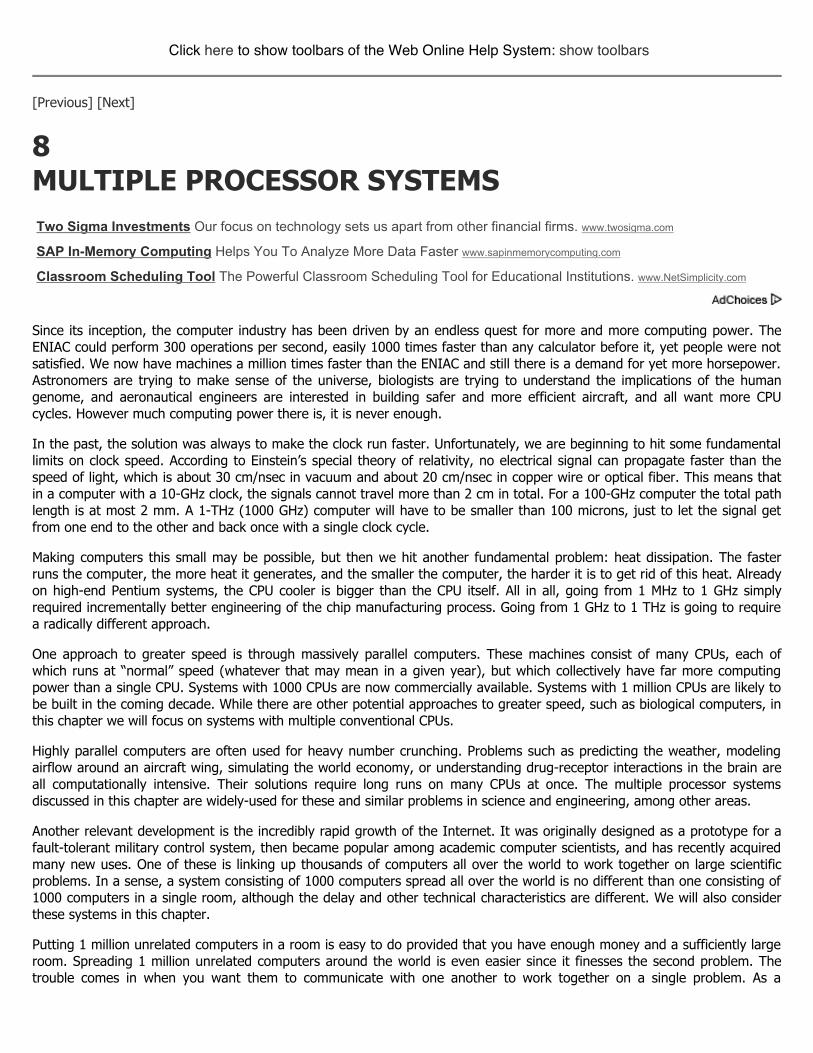

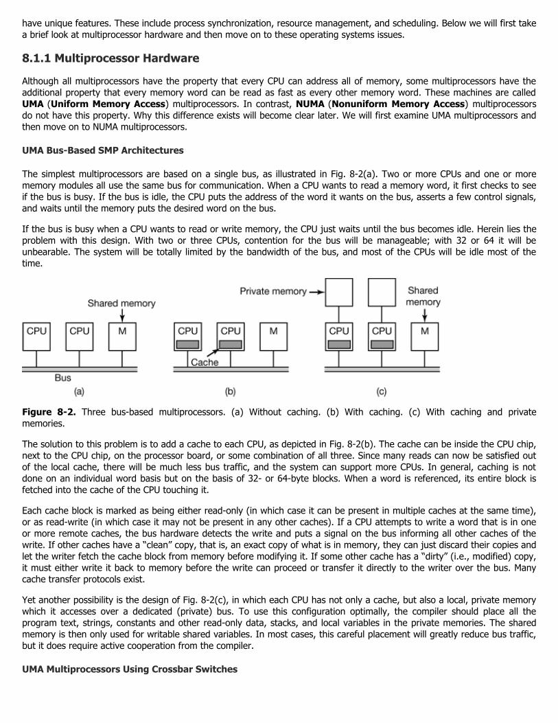
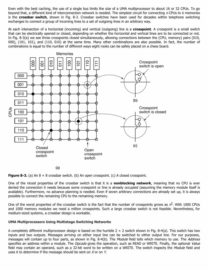
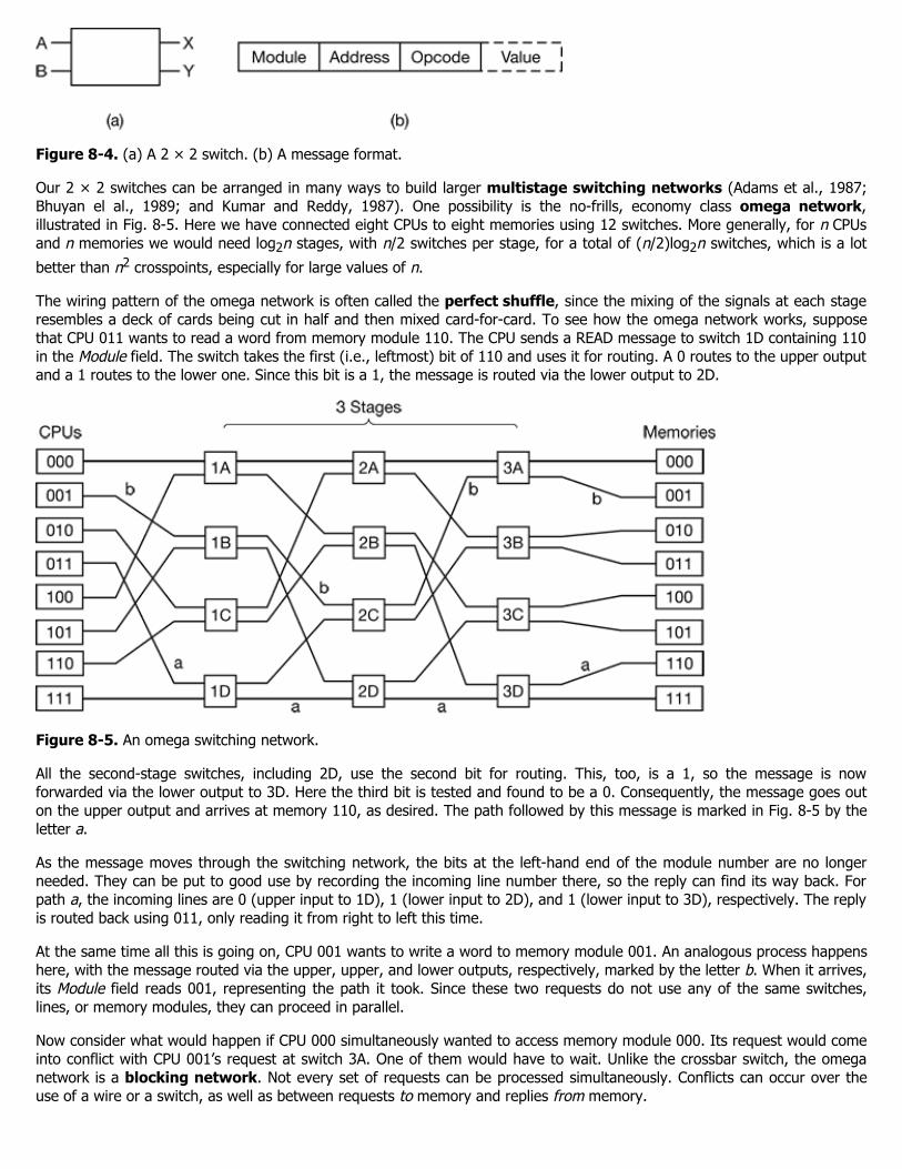
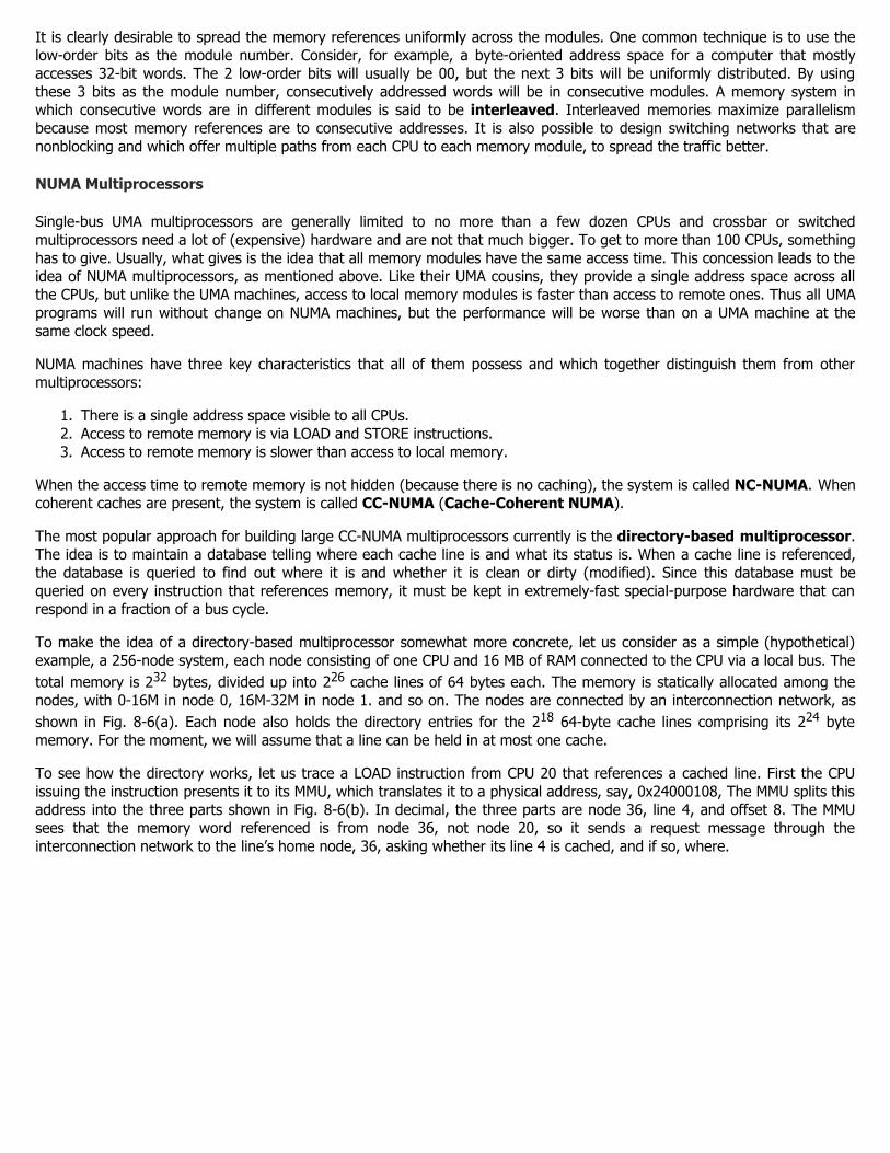

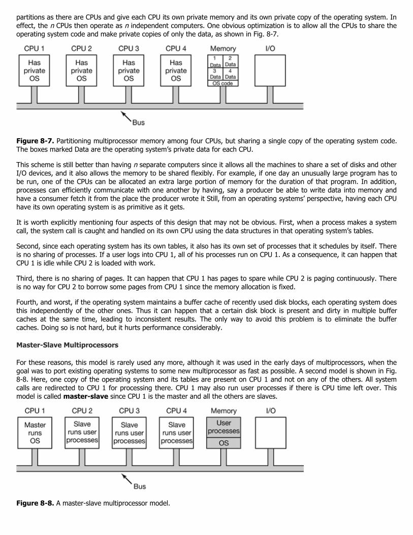
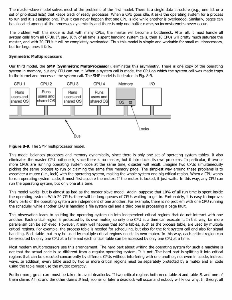
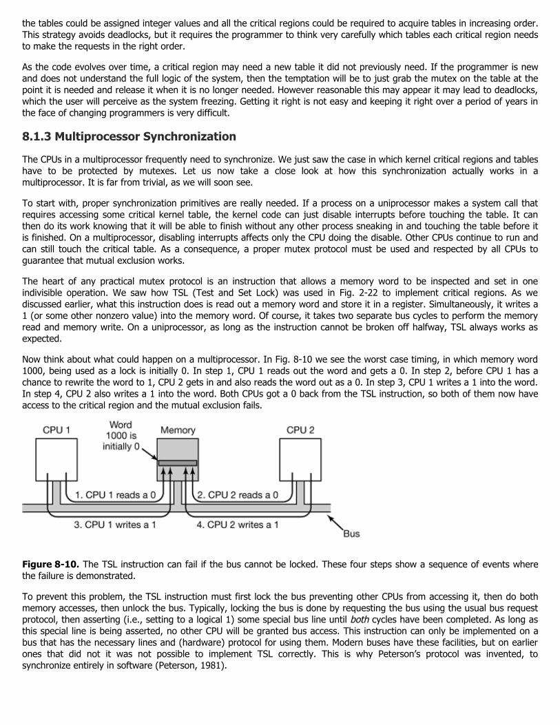
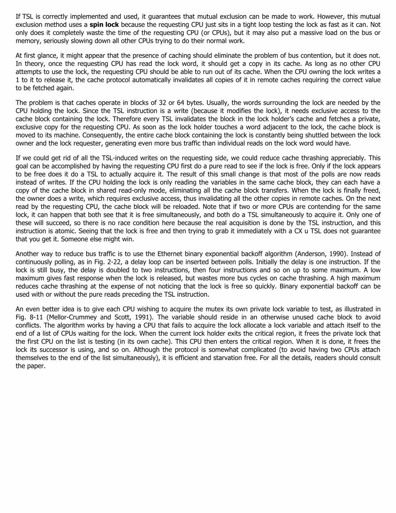
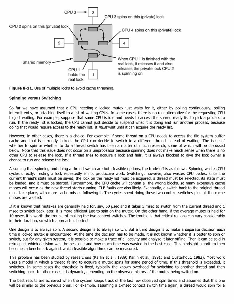
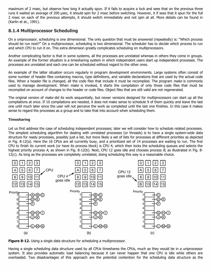

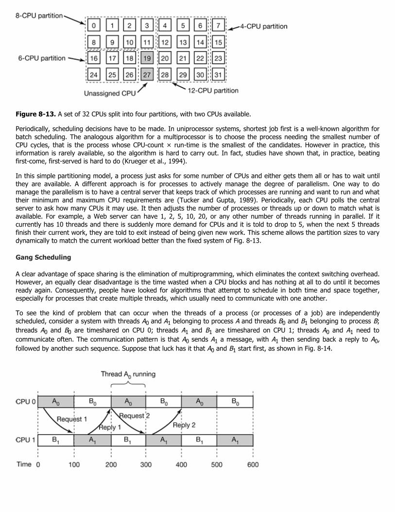

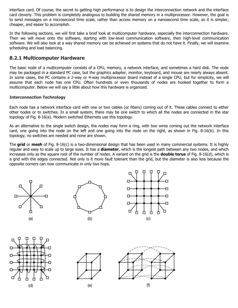
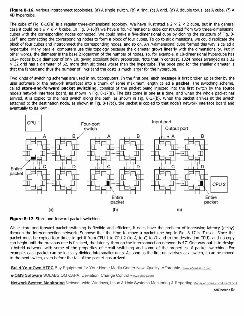
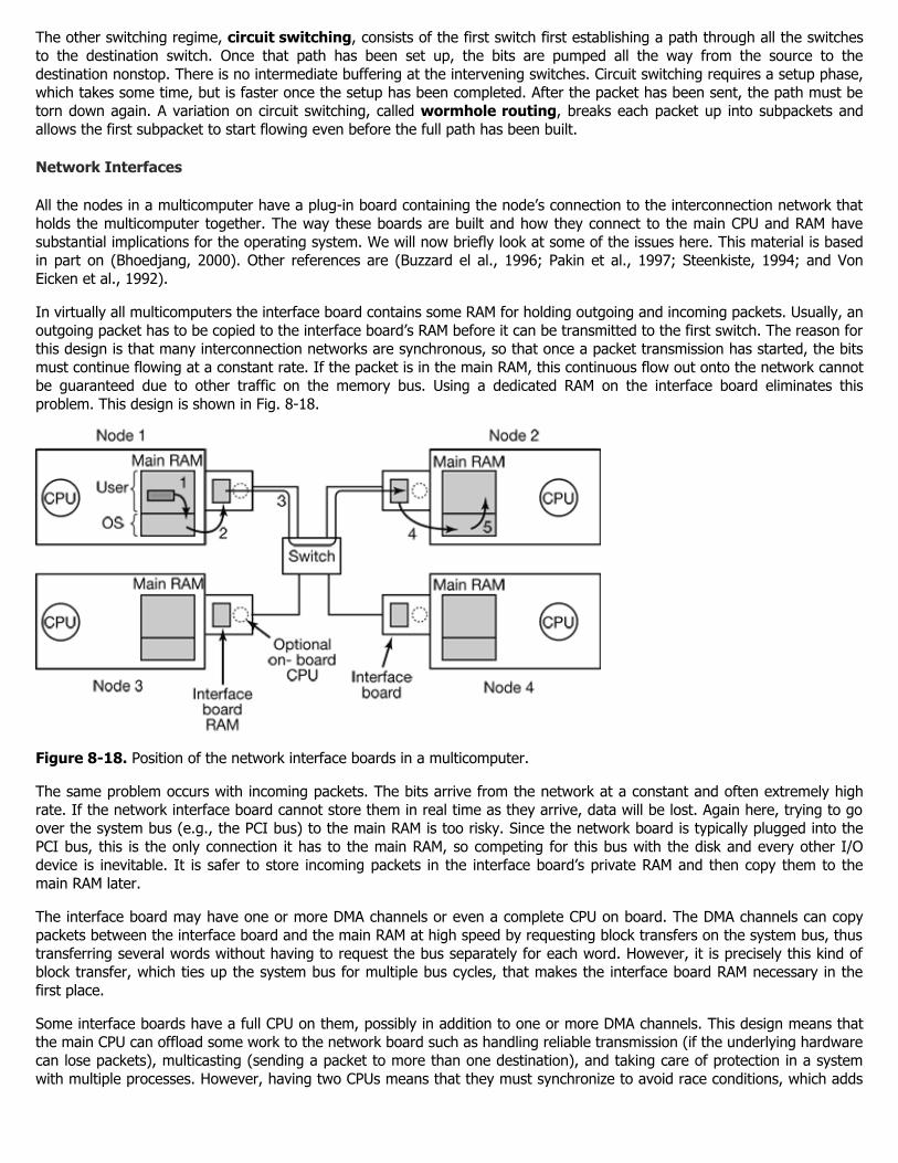
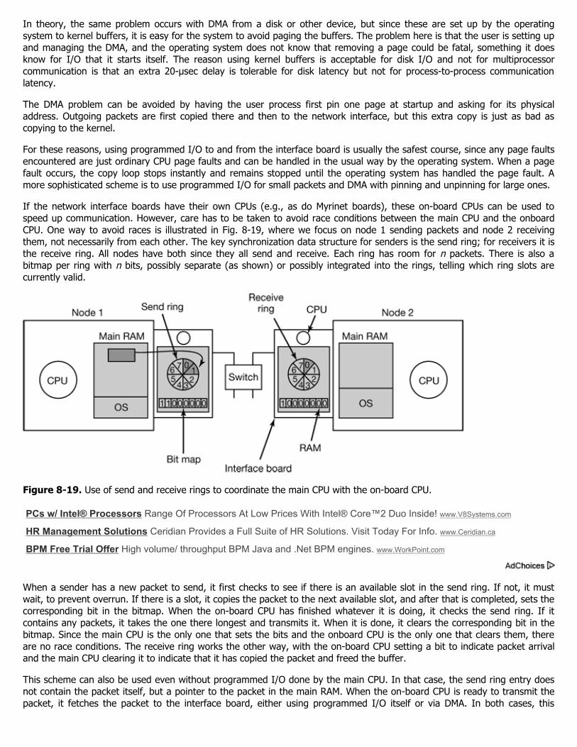
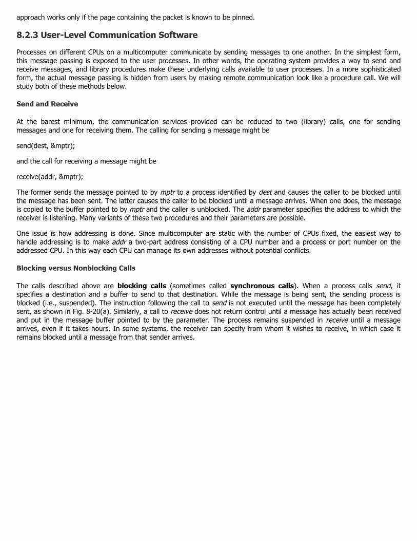


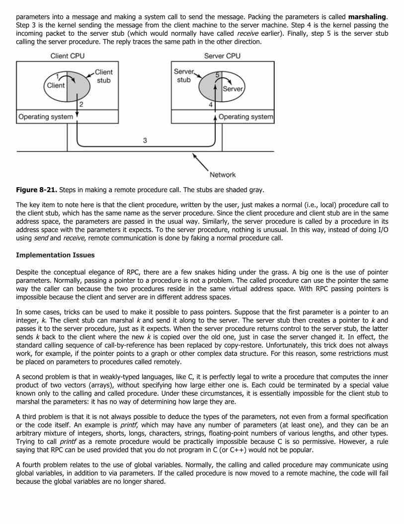
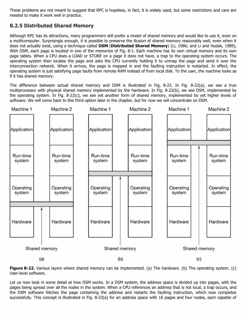
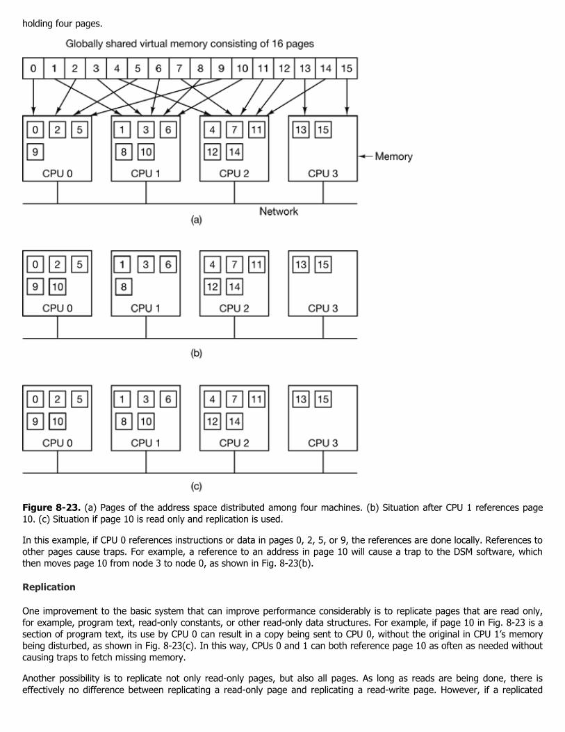
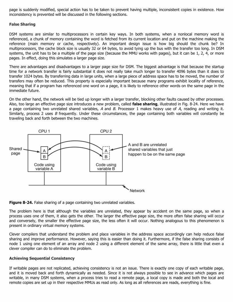
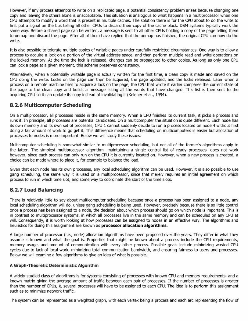

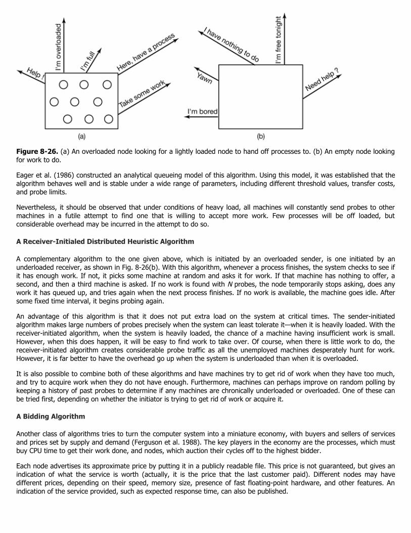
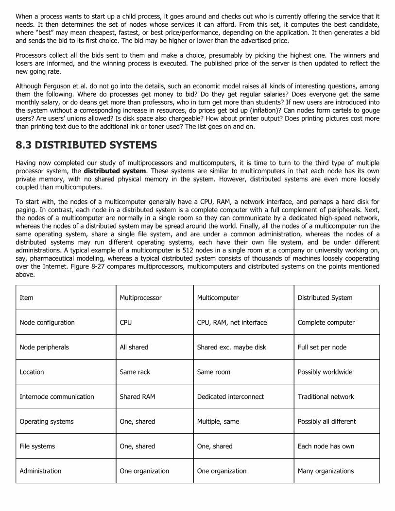


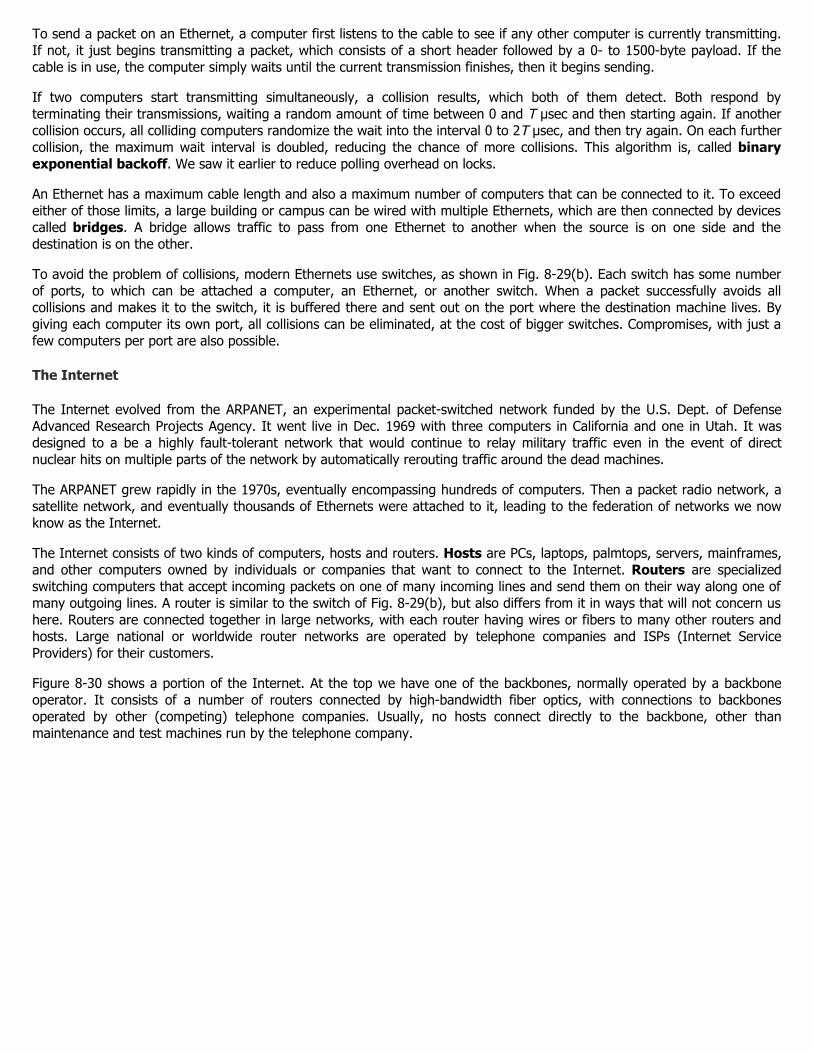
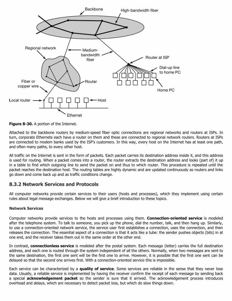
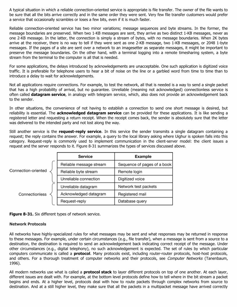


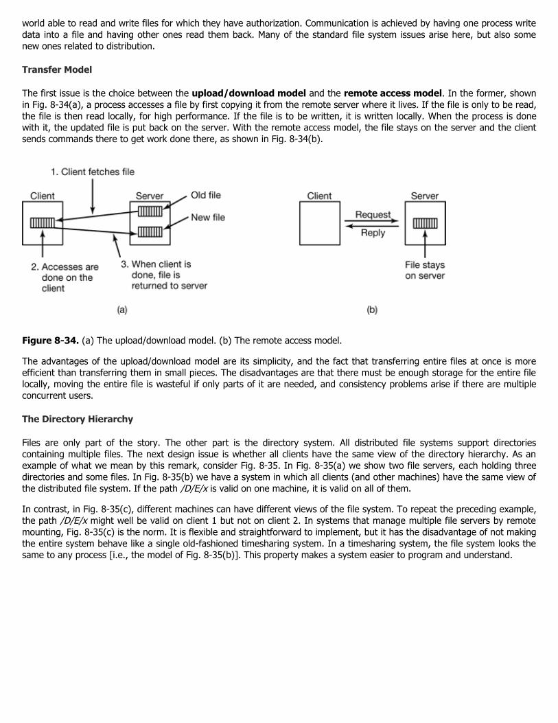


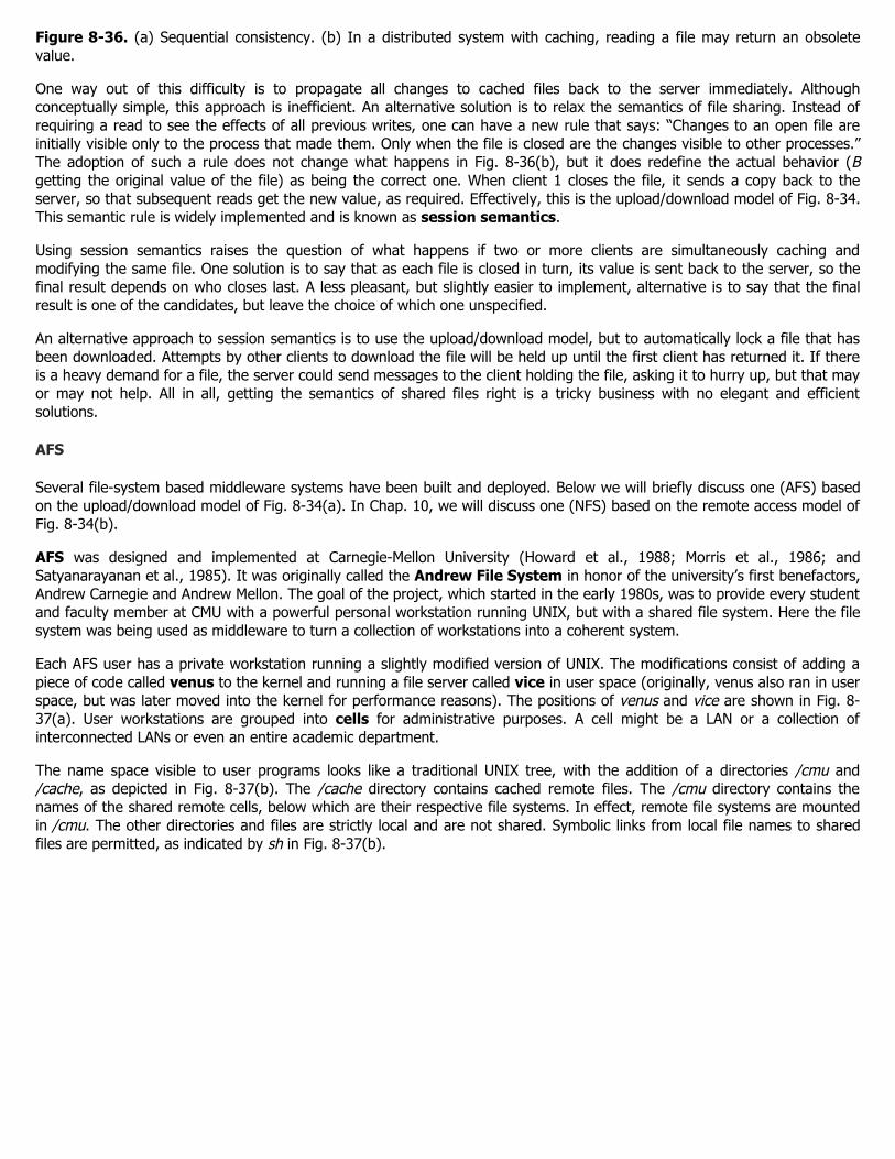
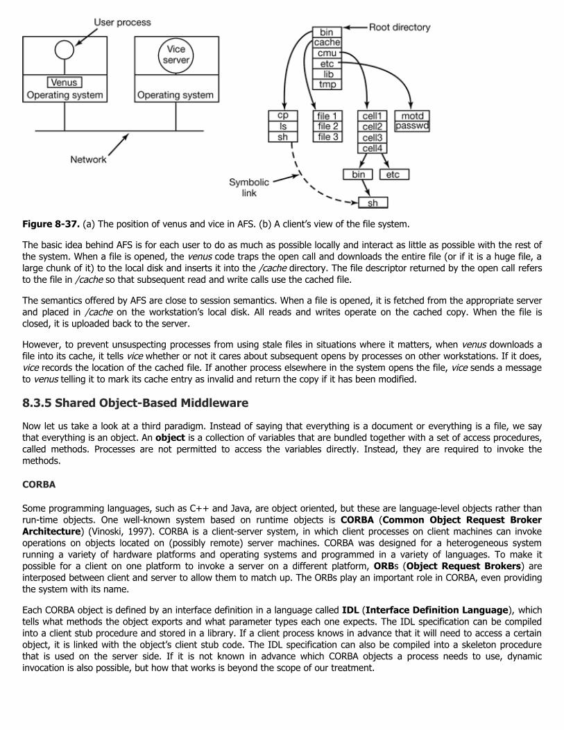
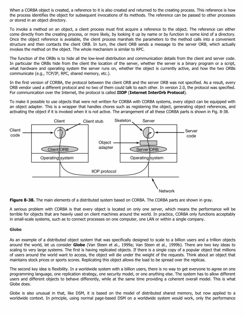
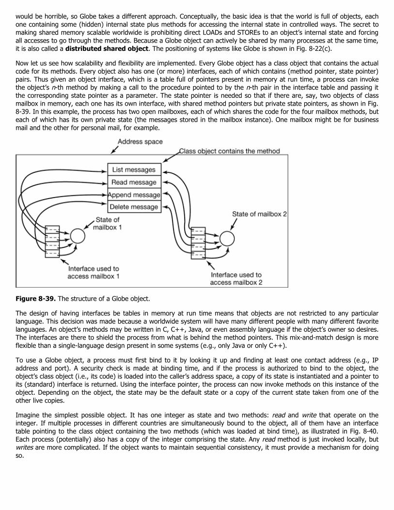

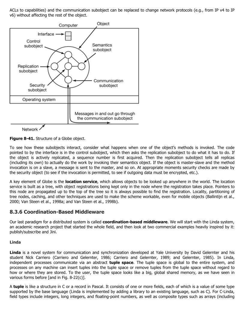
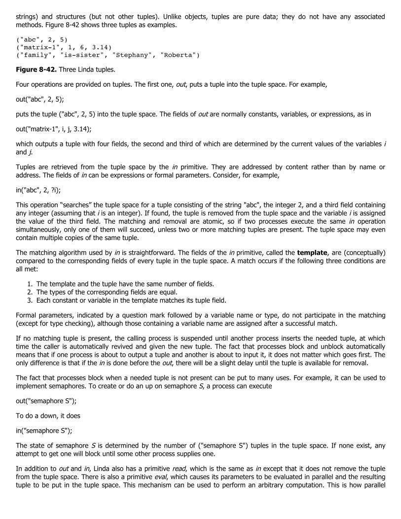


![Using Multiple Input, Multiple Output Formal Control to ... · Inputs and Multiple Outputs [11]. The example controller senses the frame rate and power of a processor, compares them](https://static.documents.pub/doc/80x56/5fa7481d122a1b76197a5993/using-multiple-input-multiple-output-formal-control-to-inputs-and-multiple.jpg)


