HX-01 HEAT EXCHANGER CONDITION ASSESSMENT PROGRAM DOCUMENT TYPE: CLASSIFICATION: REVISION: EFFECTIVE DATE: REVIEWER: APPROVAL AUTHORITY: PROCEDURE OWNER (title): Controlled Reference N/A I February 25, 2004 N/A Department Manager Group Head OWNER GROUP: Engineering Programs IftforMatk jfl to's recor Was deleted In 8ccordance ihteFedmo Ac 0MOfItfnf FO 3-5
Transcript
HX-01
HEAT EXCHANGER CONDITIONASSESSMENT PROGRAM
DOCUMENT TYPE:
CLASSIFICATION:
REVISION:
EFFECTIVE DATE:
REVIEWER:
APPROVAL AUTHORITY:
PROCEDURE OWNER (title):
Controlled Reference
N/A
I
February 25, 2004
N/A
Department Manager
Group Head
OWNER GROUP: Engineering Programs
IftforMatk jfl to's recor Was deletedIn 8ccordance ihteFedmoAc 0MOfItfnfFO 3-5
POINT BEACH NUCLEAR PLANT HX-01Revision 1
HEAT EXCHANGER CONDITION ASSESSMENT February 25, 2004PROGRAM
TABLE OF CONTENTS
SECTION TITLE PAGE
1.0 PURPOSE .32.0 DISCUSSION .43.0 RESPONSIBILITIES .44.0 QUALIFICATIONS .65.0 HEAT EXCHANGER INSPECTION SCOPE .76.0 MATERIAL DEGRADATION ISSUES .97.0 INSPECTION TECHNOLOGIES .128.0 CLEANING OF HX'S .139.0 BIO/SILT FOULING INSPECTIONS .1410.0 PLUGGING OF HEAT EXCHANGER TUBES .1611.0 PROGRAM IMPLEMENTATION .1712.0 TUBE DEGRADATION TESTING: DATA GATHERING & ANALYSIS .1813.0 EQUIPMENT PROGNOSES .1914.0 REMAINING LIFE CALCULATION .1915.0 REFERENCES .2016.0 BASES .20
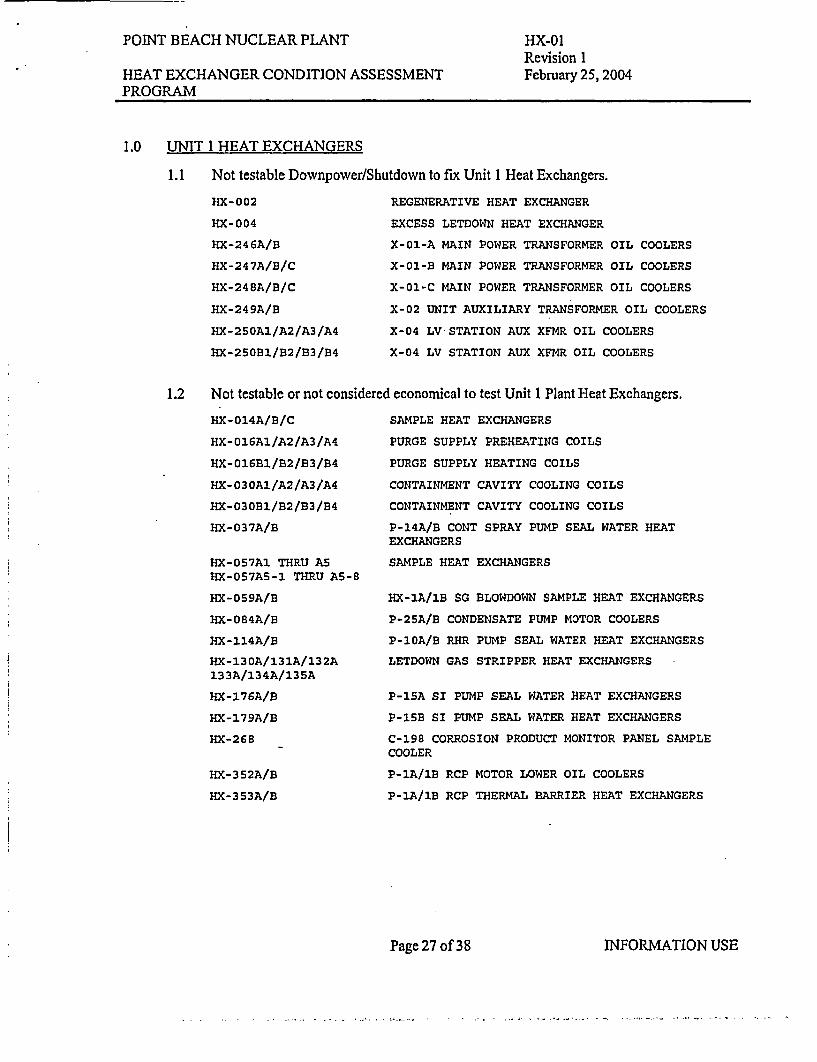
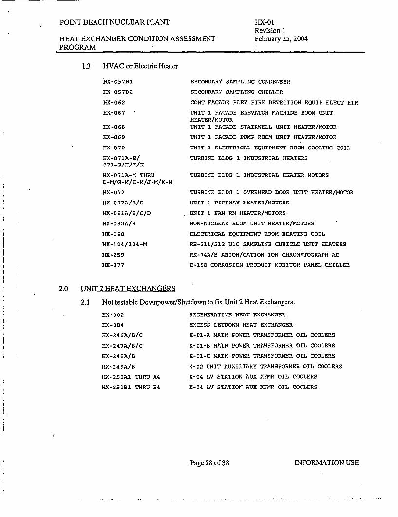
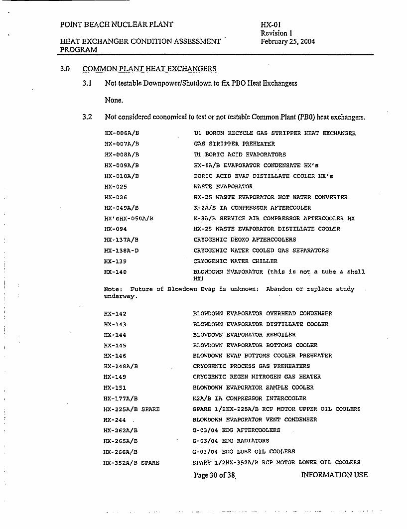
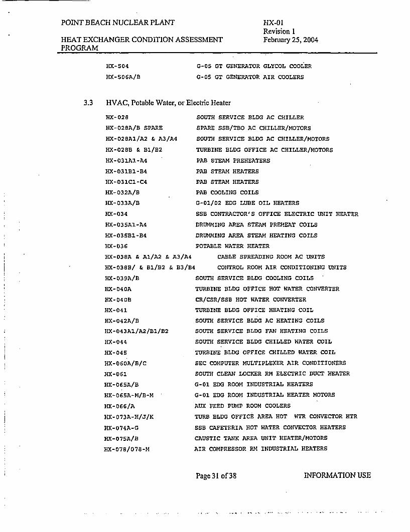
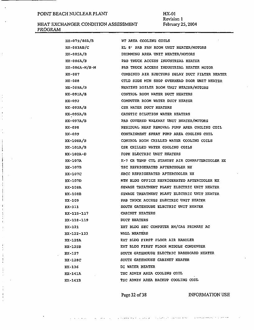
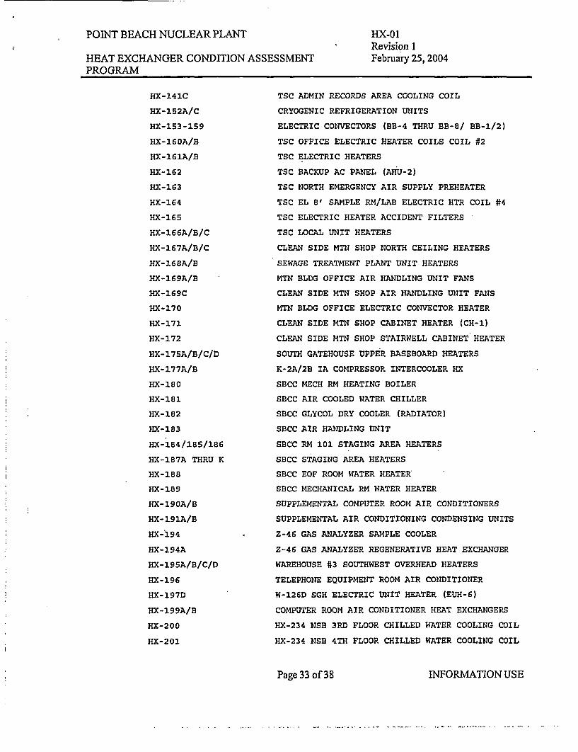
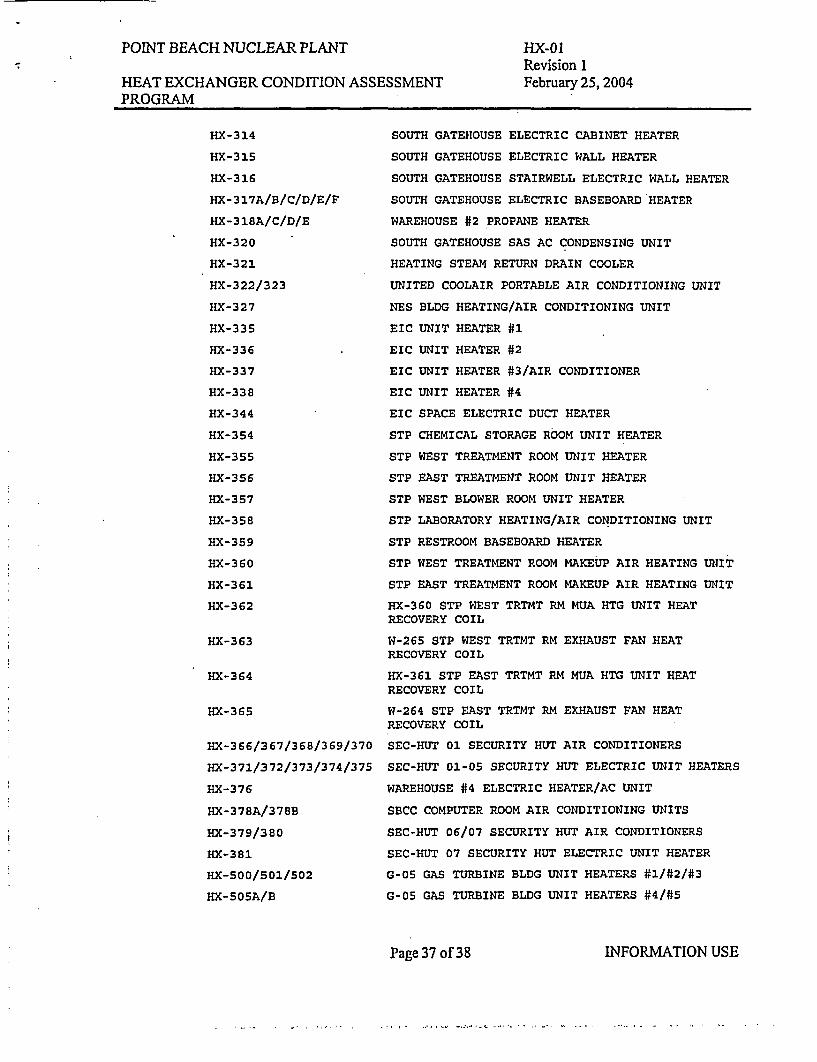
APPENDIX A IN SCOPE HEAT EXCHANGERS ................................................................... 22APPENDIX B NO SCHEDULED INSPECTIONS RUN TO FAILURE HEAT EXCHANGERS .... 26
ISSUED AS SEPARATE DOCUMENTS:
APPENDIX C UNIT I OUTAGE CYCLE INSPECTION SCHEDULE
APPENDIX D UNIT 2 OUTAGE CYCLE INSPECTION SCHEDULE
APPENDIX E ANNUAL CYCLE INSPECTION SCHEDULE
Page 2 of 38 INFORMATION USE
POINT BEACH NUCLEAR PLANT HX-01Revision 1
HEAT EXCHANGER CONDITION ASSESSMENT February 25, 2004PROGRAM
1.0 PURPOSE
1.1 The purpose of the Heat Exchanger Condition Assessment Program(HXCAP) is tomaximize plant reliability and to forecast repair or replacement of important plant heatexchangers due to material degradation, while at the same time minimizing inspectionand cleaning cost. This is accomplished by utilizing various Non DestructiveExamination (NDE) methods to assess material flaws and corrosion/erosion of thedifferent parts of certain heat exchangers to identify and trend the more common materialdegradation problems that occur in heat exchangers. This procedure also providesgeneral cleaning recommendations to prevent further material degradation where bio/siltfouling or scale buildup is expected.
1.2 This program is also used to implementa of the PBNP 3Dm3Specifically for monitoring GL 89-13 HX's for erosion and corrosion (GL 89-13 ActionItem ILI). In addition this program will be used to report as found Heat ExchangerBio/Silt fouling (GL 89-13 Action Item II and 111).
1.3 This program includes all plant heat exchangers except for the Steam Generators. Theprogram classifies the heat exchangers into groupings based on their importance to theplant and their inspectability. Most inspection efforts will be focused on the inspectableheat exchangers that are important for plant operations.
1.4 This program document excludes all Section XI weld inspections and the FW Heatershell thinning as they are covered under the PBNP Inservice Inspection Program, and thePBNP Flow Accelerated Corrosion Program. This program exclude rmatperformance testing.
how Ts A7 &
+cvi jvel, M
Page 3 of 38 INFORMATION USE
-
POINT BEACH NUCLEAR PLANT HX-01Revision 1
HEAT EXCHANGER CONDITION ASSESSMENT February 25, 2004PROGRAM
2.0 DISCUSSION
2.1 Point Beach Nuclear Plant operates in a competitive market where the focus is onreducing maintenance cost and maximizing plant reliability to remain competitive. Assuch, inspection resources for balance of plant (BOP) heat exchangers must be spentwisely and effectively to minimize tube leaks, extend the availability, and forecast timelyreplacement of essential heat exchangers.
Keys to a successful BOP heat exchanger condition assessment program include:
* Minimizing tube leaks in critical equipment by targeting key heat exchangers forinspection.
* Devising an appropriate sample based inspection scheme to ensure that aninspected component will remain trouble free during operation.
* Assessing conditions of the heat exchangers using appropriate and reliableinspection techniques.
* Applying realistic tube plugging criteria and reducing insurance plugging.* Planning for timely heat exchanger replacement by calculating remaining heat
exchanger operating life.
3.0 RESPONSIBILITIES
3.1 The Engineering Programs Manager has overall responsibility for the development,approval, administration, and implementation of the Heat Exchanger ConditionAssessment Program at PBNP. The Engineering Programs Manager shall be responsiblefor designating an individual who shall function as the Heat Exchanger ConditionAssessment Program Engineer, and ensure that appropriate training is provided forindividuals involved in Heat Exchanger Condition Assessment.
3.2 The Engineering Programs Inspection Supervisor reports to the Engineering ProgramsManager and provides administrative and technical direction to the Heat ExchangerCondition Assessment Program Engineer.
3.3 The Heat Exchanger Condition Assessment Program Engineer shall be responsible forthe following program actions:
3.3.1 Develop and maintain Heat Exchanger Condition Assessment Programdocuments in accordance with the applicable NMC Implementing Standards.
3.3.2 Ensure cost effective implementation and administration of the HeatExchanger Condition Assessment Program.
3.3.3 Ensure effective communication between plant personnel and/or otherorganizations responsible for providing support services directly related toheat exchanger inspection for the Heat Exchanger Condition AssessmentProgram.
Page 4 of 38 INFORMATION USE
POINT BEACH NUCLEAR PLANT HX-01Revision 1
HEAT EXCHANGER CONDITION ASSESSMENT February 25, 2004PROGRAM
3.3.4 Review and approval of NDE contractor's techniques, procedures, equipment,calibration standards, and personnel qualifications prior to the start of exams.
3.3.5 Track and trend degrading heat exchanger conditions on a component basis toprovide system engineers and plant management with information related tothe estimated life of the heat exchangers.
3.3.6 Ensure corrective actions are initiated and coordinated for tube plugging andtube pulling for metallurgical examination.
3.3.7 Maintain eddy current database program and picture records of as found heatexchanger conditions where pictures are required or suggested in this programdocument.
3.3.8 Preparation of unit and annual cycle reports for the heat exchangers inspectedduring the previous cycle. This report shall include heat exchangersinspected, as found conditions, and recommendations for future inspections orcorrective actions.
3.3.9 Maintain tube plugging criteria for in-scope HX's and overall amount of tubeplugging per heat exchanger
Page 5 of 38 INFORMATION USE
POINT BEACH NUCLEAR PLANT HX-01Revision 1
HEAT EXCHANGER CONDITION ASSESSMENT February 25, 2004PROGRAM
4.0 QUALIFICATIONS
4.1 Visual Assessment Upon Opening:
4.1.1 Material Degradation:
There is no specific qualification required for this inspection as the emphasisis identifying areas of material degradation that are clearly visible with aspecific inspection of the component areas (look at, not just glance at).
4.1.2 Bio/Silt Inspections:
GL 89-13 Bio/Silt inspections shall be performed by an engineer withexperience and the knowledge to recognize the different types of bio/siltfouling (silt, mussel or clam, slime, tubercles, debris, weeds, etc), and who isknowledgeable on determining when tubes are effectively plugged from athermal performance standpoint.
4.2 NDE Test Technicians:
Technicians performing any form of UT, Eddy Current Testing (ECT), and Remote FieldTesting (RFT) shall be qualified to SNT-TC-lA, or an equivalent program. Personnelperforming NDE data analysis shall be qualified as a level H, or higher.
4.3 Program Engineer:
The HXCAP Engineer is qualified in accordance with NMC Fleet Mentoring Guide,Eddy Current Testing, and any other specific mentoring guide developed in the future.
4.4 Vendors:
Vendors shall submit their test procedures for review and acceptance by PBNP prior tothe start of any work. Vendors shall submit appropriate certification papers for theirpersonnel to the HXCAP Engineer prior to the start of any exam.
Page 6 of 38 INFORMATION USE
POINT BEACH NUCLEAR PLANT
HEAT EXCHANGER CONDITION ASSESSMENTPROGRAM
HX-01Revision 1February 25, 2004
5.0 HEAT EXCHANGER INSPECTION SCOPE
5.1 Classification of Heat Exchangers:
In order to utilize resources effectively the heat exchangers at PBNP are sorted into twogroups: Those that are "In Scope" for scheduled inspections and those that are not. Thesecond group is also a Run -To-Failure (RTF) classification by definition (it is RTF if weare not going to inspect to prevent failure). The later group may have correctivemaintenance or special inspections done when appropriate.
The design of PBNP is such that there are no HX's who's isolated failure could directlyaffect the health and the welfare of the public or nuclear safety, which provides a sortingcriteria based more on plant reliability and on heat exchangers that are important to theoperation of the plant (including nuclear safety) even though they may have back-ups.The following is the list of criteria used to determine how a HX is sorted:
0
0
0
0
0
S
S
S
Will failure of the HX require downpower or shutdown for repairs.Is the HX testable by normal maintenance and BOP NDE techniques (accessiblevia bolting, tube configuration allows access for probes, etc)Is the HX in the GL 89-13 Program.Would the HX require an LCO for maintenance.Would a leaking tube probably cause substantial damage to other equipmentIs the HX important to plant operations, has a backup, but it is economical for usto inspect and trend its condition due to the likely cost of repairs or replacement.Is the equipment not being used, or likely to be abandoned soon.Is the HX part of the general HVAC system or an electric heater.Is there sufficient information about a HX in order to determine its inspectability
Iand materials of construction. X .oier
* Plant Management Discretion
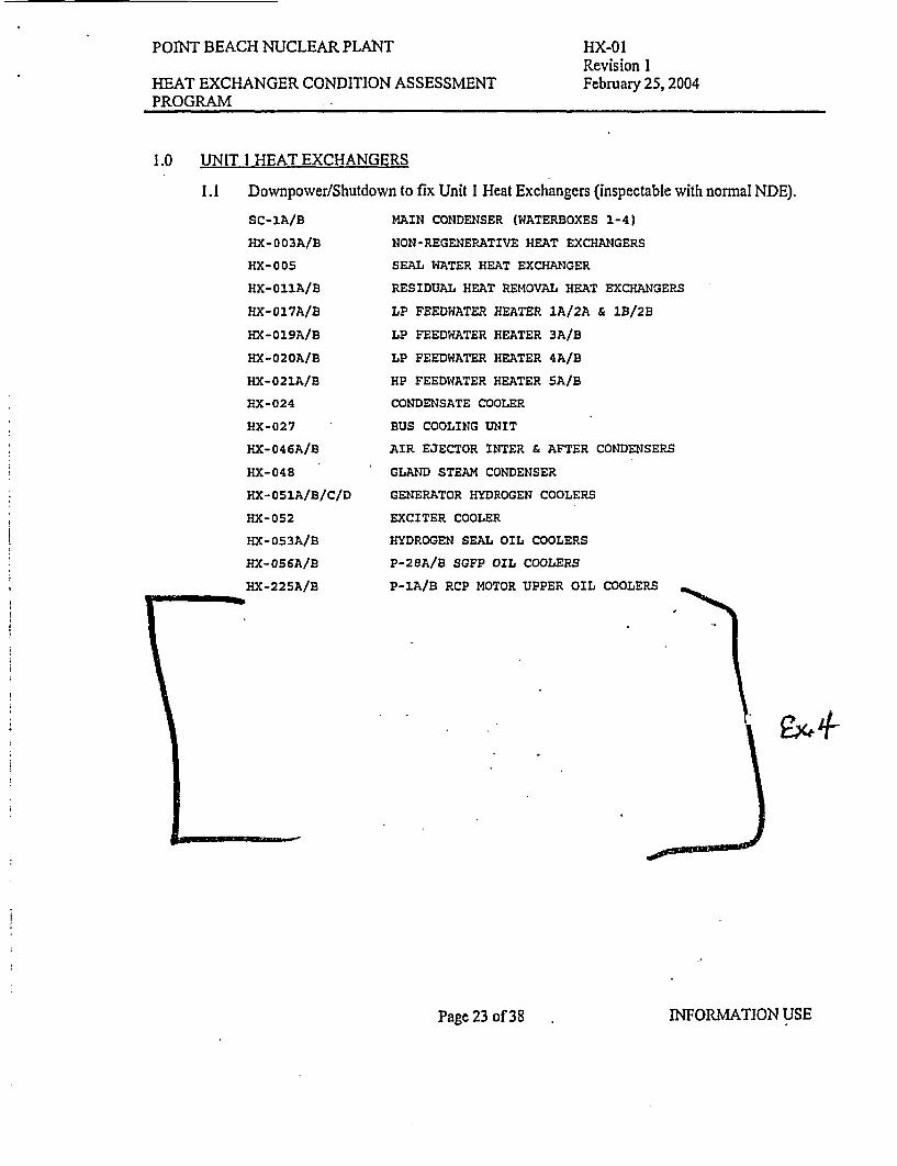
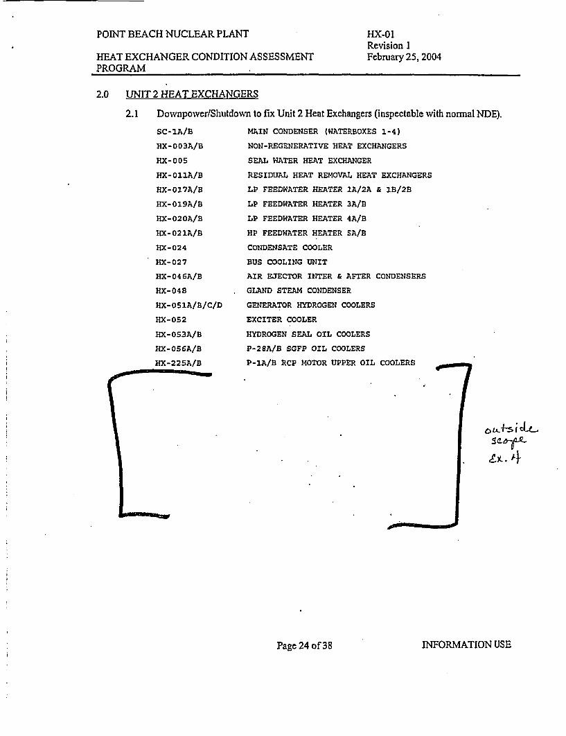
The "In Scope" heat exchangers are listed in Appendix A, and those not scheduled forroutine inspection / RTF heat exchangers are listed in Appendix B.
5.2 Inspection Type & Scope
All "In Scope" heat exchangers (Appendix A) shall have an inspection scheduledeveloped concerning the type of inspection, the technology used, the extent of theinspection, and the planned interval of the inspections.
5.2.1 Inspection type is driven by the anticipated or known condition specific toeach heat exchanger: Bio/silt, channel or shell corrosion, tube degradation,etc. (See section 6 below for more information).
Page 7 of 38 INFORMATION USE
POINT BEACH NUCLEAR PLANT HX-01Revision I
HEAT EXCHANGER CONDITION ASSESSMENT February 25, 2004PROGRAM
5.2.2 The technology used will be controlled by the types of defects you are lookingfor and the materials of construction. For example channel or shell corrosiontypically can be seen with a simple visual inspection or with ordinary UT within-house people. Tube degradation mechanisms usually require specializedtest equipment.
5.2.3 The extent of the inspection is driven by the two factorsc an ;expected iHX egradation areas. Tube degradation inspection using ECT,
an azed testing typically involves outside vendors andset-up time. Thus, smaller heat exchangers typically will have 100% of thetubes tested as the cost to test the remaining tubes is minimal once the vendoris set-up. Sample patterns are typically used with larger HX's.
The break point between 100% tube inspection and use of a sample pattern istypically between 300 and 500 tubes depending on the length of the tubes inthe HX. This is not a hard rule, as there are cases where samples will be usedon smaller HX's and other cases where 100% of the tubes will be tested onlarger HX's. Importance of the HX, level of concern on tube condition,ALARA, difficulty of gaining access, and other factors all weigh into thedecision as to what is the appropriate test sample for a given HX and a giventest.
100% baseline inspection of all new or retubed HX's is recommended toidentify all existing tube flaws and construction damage. A test patternsequence to sweep all the tubes over a series of inspections is recommendedfor large HX's if an initial baseline cannot be done.
5.2.4 An established interval is essential to uncovering an inherent or developingproblem before failure occurs. This interval is dependent on the materials ofconstruction, the type of degradation you are monitoring for, the known extentof the problem and expected growth of degradation. EPRI's PM optimizationprogram has general industry tube degradation monitoring intervals for wherethere is no known specific problem. Alternately, EPRI's Heat ExchangerComponent Risk Calculator can also be utilized. The EPRI guidelines aregeneral in nature and actual plant equipment history and local tube
6Lmaterial/application issues should control test intervals for affected HX's.
5.2.5 Specific inspection schedules, component history, and recommendations arelisted in appendices C, D, and E (Unit 1 Outage, Unit 2 Outage, and AnnualCycle inspection schedules). Also, these appendices may be used to compileknown construction and plugging data for HX's that are not inspected in orderto provide a standard location for such information.
Page 8 of 38 INFORMATION USE
POINT BEACH NUCLEAR PLANT HX-01Revision 1
HEAT EXCHANGER CONDITION ASSESSMENT February 25, 2004PROGRAM
6.0 MATERIAL DEGRADATION ISSUES
6.1 Channel. Cover, and Shell Degradation Modes.
Heat exchanger channels, covers, and shells are typically made of either carbon steel or a300 series SS. General corrosion and degradation is typically a concern only in rawwater applications. Controlled chemistry loops (condensate, CCW, etc) rarely have anysignificant or unusual degradation.
Raw water applications provide the mixture of a constant supply of oxygenated water andvarious forms of biological organisms, silt, and debris. This combination can readilyattack and degrade carbon steel and may attack stainless steels.
Raw water heat exchangers are built with a corrosion allowance to provide "excess"material to be degraded away without affecting design function.
The most common form of unusual degradation is under-deposit pitting from biofouling.These inspections need to be done after all biofouling and silt is cleaned from the channeland cover.
Another form of degradation that needs to be watched for is galvanic corrosion of thetubesheet or channel when a raw water heat exchanger has been retubed with a morenoble tube material than it was designed for. There are known industry problems withcertain common retube options such as using SeaCure tubes with a carbon steeltubesheet. These problems are typically controlled by epoxy coating the tubesheet andchannel shortly after retubing.
These forms of degradation are easily seen with a simple visual inspection of the channeland cover when the heat exchanger is opened. Very heavy and loose rust scale, pits ordepressions in the normal shape is all that is needed for initial detection. Once detectedUT measurements can be taken to trend and predict remaining life. UT inspection ofshell thickness can be done for any heat exchangers with SW on the shell side (such asthe PBNP SFP Coolers).
Epoxy coating of channels and covers needs to be done carefully and properly to avoid asituation where galvanic corrosion will effectively drill a hole through the base metalwherever there is a defect in the epoxy coating. Pits and cracks in epoxy coating shouldbe promptly repaired.
Page 9 of 38 INFORMATION USE
.
POINT BEACH NUCLEAR PLANT HX-01Revision I
HEAT EXCHANGER CONDITION ASSESSMENT February 25, 2004PROGRAM
6.2 Tube Degradation Modes
EPRI's "Heat Exchangers: An Overview of Maintenance and Operations" (TR-106741)list the 15 typical failure modes of heat exchanger tubes. This list is far from complete asthere are many other known degradation mechanisms that can affect tubes under the rightsituation. For example, the mechanism for the KNPP 2002 CCW failure is not listed.(circumferential cracking in the roll transition zone).
Only 2 of the 15 typical failure modes relate to bio/silt fouling of tubes from raw watersources (debris pits, under deposit pitting). Several of the other 13 typical modes oftube failure apply to any heat exchanger. Fatigue damage will typically be the mostcommon mode of failure of heat exchanger tubing in the event that a HX is designed,manufactured, and operated properly for its service.
6.3 Raw Water Tube Material Issues
There are some local issues related to the raw water heat exchangers and choices of tubematerials at PBNP due to the use of Lake Michigan as our heat sink.
6.3.1 Copper and Copper Alloys:
As of 2003, lake Michigan contains a bacteria that rapidly degrades CuNi tubematerials to the point that CuNi tubing typically last only a few years (CuNi isnot recommended for any raw water application at PBNP, and has failed innumerous heat exchangers).
This bacterium did not exist here 40 years ago. Plants on Lake Michigan used90/10 CuNi tubing successfully at that time. Dumping of bacteriacontaminated bilge water from shipping and barge traffic has spread thebacteria here. Currently, other forms of bacteria that will attack other copperalloy tubing exist in areas frequented by both national and internationalshipping (these bacterium are often alloy specific). It is projected that thosebacteria will at some point spread and establishes themselves in LakeMichigan. The timing of this is an unknown and could occur in the nextseveral years, or may take decades. Olin Fineweld, who used to be the largest
- < A manufacturer of copper alloy tubing in the USA, no longer recommends ther\ 'y + use of copper based tube alloys on any raw water lake or river application
AM ad 4 h because of the expected spread of these bacterium.
Page 10 of 38 INFORMATION USE
POINT BEACH NUCLEAR PLANT HX-01Revision I
HEAT EXCHANGER CONDITION ASSESSMENT February 25, 2004PROGRAM
Currently both Copper and Admiralty Brass tubing are showing a normalgood life at KNPP and PBNP (15-30 years) in raw water service. Thesematerials are being reused in replacement and retubing of smaller heatexchangers (larger heat exchangers should be switched away from copperalloys due to the financial risk). However, continued monitoring of the HXtube condition is required due to the expected future arrival of bacteria thatwould start the degradation process. This degradation mechanism wouldprobably take a few years providing time for a focused replacement programof the affected heat exchangers).
Recommended eddy current inspection should be staggered such that PBNP islooking at a few copper alloy heat exchangers every year or so. This way itwill be possible to see early indications of any bacteria based degradation.Some Admiralty Brass heat exchangers should be routinely tested just to trendthis issue and assess how other Admiralty Brass tubed heat exchangers areaffected.
6.3.2 300 & 400 Series SS:
%,'e J n'A In 2003, KNPP confirmed the presence of a bacteria that will causeunder-deposit MIC pitting in 300 and 400 series SS tubing (KNPP has 439 SScondenser tube leaks that have been traced to under-deposit MIC pitting).
Va t 1 These bacteria types have been known to have been active in the Milwaukeearea since the late 90's.
Trent Tube has confirmed that the bacteria types that attack 439 SS will alsoattack 300 series SS as there is not any real difference in the protection levelof these alloys to under-deposit pitting.
PBNP has had good results to date with 304SS in constant flow raw waterapplications. It is now critical that extra attention be paid to proper cleaningof the tubes to prevent hard deposits. The problem can probably be managed(if not prevented) by keeping the tubes clean.
All 304 SS tubes in lake water applications should be frequently monitoredbecause this type of degradation would probably be fairly rapid under the rightconditions. Recommended inspection interval is 1.5 years on the PB MainCondensers because this problem will probably show up in the hot zones ofthe condenser before it would affect other raw water heat exchangers with304 SS.
There is a special concern with the SFP heat exchangers due to the fact thatthe SW is on the shell side where the tube deposits cannot be seen or cleanedand access for eddy current testing is more difficult due to the SFP water onthe tube side and the resulting hot particle and ALARA issue (tent and bubblesuit is required for eddy current testing). In addition it is not practical to testthe U-bend section of the tubes.
Page II of 38 INFORMATION USE
POINT BEACH NUCLEAR PLANT HX-01Revision I
HEAT EXCHANGER CONDITION ASSESSMENT February 25, 2004PROGRAM
6.3.3 SeaCure
SeaCure is highly resistant to the various bacteria induced corrosions anderosion. However eddy current inspectability is limited due to its ferriticnature. The tube must be magnetically saturated, the saturation also saturatesa steel baffle such that vibration induced fretting wear and fatigue cracking atthe baffle cannot be seen.
PBNP has seen excellent results with SeaCure in raw water applications
Recommended inspection intervals for good condition SeaCuretubes range from 6 to 10 years depending on how critical theheat exchanger is and the consequence of leaks.
7.0 INSPECTION TECHNOLOGIES
7.1 Visual inspection is good for seeing unusual degradation of the channel,cover, and tube end erosion.
7.2 Ultrasonic Thickness measurement (UT) is good for detecting plate thickness loss on heatexchanger channels, covers, shells, and tubesheets.
7.3 Eddy Current Testing (ECT) is the most common method of inspecting HX tubes fordefects. It works very well on non-ferritic tube materials (Copper alloys, 300 Series SS,Titanium, etc). Ordinary "bobbin" ECT typically can see over 90% of all common tubedegradation mechanisms and the probes are inexpensive.
ECT's principal limitation in non-ferritic tubing is that ordinary bobbin coils cannot goaround U-Bends or see circumferential crack indications. There are specialized probes, atsubstantially increased cost, that can go around the larger U-Bends, look forcircumferential cracking, and look for other rare defects. Use of these specialized probesis typically only warranted in the balance of plant heat exchangers if strong evidenceexist of these specific degradation mechanisms. A cost benefit analysis may need to bedone on small to medium sized HX's before proceeding with the specialty technology (itmay be cheaper to replace the HX than to test it with the special probes).
Page 12 of 38 INFORMATION USE
POINT BEACH NUCLEAR PLANT HX-01Revision 1
HEAT EXCHANGER CONDITION ASSESSMENT February 25, 2004PROGRAM
Magnetic Saturation "bobbin" probes expand eddy current testing into the straight tubethin wall ferritic tube materials (439 SS, SeaCure, etc). This comes at a modest increasein cost for typical tube sizes and wall thickness seen in most power plant heat exchangersas the magnetic saturation probes are more expensive and wear out quickly (the probesticks to the tube). This testing gets more expensive for 3/8" or 1/2" tube OD's becauseof the cost of the small and powerful magnets required for those applications (and theprobesw e"'out faster yet). The limitations are that magnetic saturation probes areblinded by the baffles and support plates, and that they cannot go around U-Bends.
7.4 Remote Field Testing (RFT) is an electromagnetic technique similar to eddy current, butwhich can be used on heavy wall ferritic tubing. It is also possible to build an RFT probeto go around U-Bends (however, normal manufacturing stress relief heat treatment of theU-bend may limit sensitivity to smaller defects). RFT is typically not as sensitive tosmall pits and cracks as magnetic saturation ECT.
7.5 Internal Rotary Inspection System (IRIS) is a Ultrasonic Thickness (UT) method thatuses a rotating probe with water as the couplant. This technology measures the thicknessof the tube wall to several thousands of an inch and is not sensitive to the tube material orwall thickness. As such, in power plant applications, it can provide data on baffle frettingfor ferritic tubing. The probe also can get past and see dents providing a method ofexamining a heat exchanger tubing with a denting problem. IRIS, however, cannot detectsmall pits or cracks.
7.6 Radiography (RT) is sometimes used to try and spot a displaced impingement plate, orgross fouling on the shell side of a heat exchanger. This has had limited success as thetube bundle or other construction features may interfere with the necessary details;however it is worth trying as this is often much cheaper than opening a heat exchangershell.
8.0 CLEANING OF HX'S
8.1 General Cleaning Recommendations
Deposits in heat exchanger tubes cause several problems. The deposits provide a placefor Microbiologic Induced Corrosion (MIC) to occur if bacteria is in the system.Deposits promote chloride concentration cells if chlorine is present, reduce heat transfer,and with time forms hard scale which can be difficult to remove (removal techniques candamage the tubing). Bio/Silt fouling can make it impossible to get a inspection probedown a tube. Deposits also can affect the sensitivity of eddy current techniques if there isenough iron in the deposits.
Not all deposits are limited to the raw water systems. Scale buildup is known to occur infeedwater heaters (PBNP's #5 affected the fastest due to temperature), and the SteamGenerator Blowdown HX's.
The rule of thumb to remember is: "a clean tube is a happy tube."
Page 13 of 38 INFORMATION USE
POINT BEACH NUCLEAR PLANT HX-01Revision I
HEAT EXCHANGER CONDITION ASSESSMENT February 25, 2004PROGRAM
All lake water cooled heat exchangers (SW and CW systems) should be cleaned on aregular basis to prevent tube degradation and scale buildup, and prior to tube degradationinspection.
Feedwater Heaters and SG Blowdown HX's should be cleaned prior to any tubedegradation inspection. Note that PBNP was named in 2002 as one of the most thermallyefficient nuclear stations in the nation. The fact that we routinely hydrolance clean theFW Heaters about every 6 years played a part in this.
8.2 GL 89-13 Heat Exchangers
Cleaning of the GL 89-13 heat exchangers is controlled by the PBNP GL 89-13 programdocument (not all of these HX's are routinely cleaned). The GL 89-13 heat exchangersare:
All SW or CW cooled heat exchangers should be monitored for changes in Bio/Siltfouling. This can be done by filling out the "Bio/Silt Fouling Inspection Form"(PBF-7061) upon initial opening of the heat exchanger. Copies of the filled out Bio/SiltFouling Inspection Form are provided to the Biofouling Control Program Administrator,the System Engineer, and the HXCAP Engineer. There is no formal record retentionrequirement for general CW and SW cooled heat exchangers.
9.2 GL 89-13 Heat Exchangers
Bio/Silt Fouling inspection schedules of the GL 89-13 heat exchangers is controlled bythe PBNP GL 89-13 program document (not all GL 89-13 HX's are routinely Bio/SiltFouling inspected).
Bioilt Fouling inspections shall be conducted by an appropriate engineer for theG01/G02 Glycol Coolers (HX-55's) and the PAB Battery Room Coolers (HX-105A/B)as "cleaning and inspecting" is being used to meet GL 89-13 Action Item II for theseHX's. Specific records and trending must be maintained for these coolers.
Page 14 of 38 INFORMATION USE
- - -
POINT BEACH NUCLEAR PLANT HX-01Revision I
HEAT EXCHANGER CONDITION ASSESSMENT February 25, 2004PROGRAM
The acceptance criteria shall comply with section 9.3 below. Records of inspectionresults are to be documented in the WO for the specific heat exchanger. The originalBio/Silt Fouling Inspection Form shall be filed with the work order, with copies beingprovided to the Biofouling Control Program Administrator, the SW System Engineer, andthe HXCAP Engineer.
The SW System Engineer is responsible for trending the results (as per GL 89-13Program Document).
9.3 Bio/Silt Fouling Acceptance Criteria
The most common acceptance criteria for GL 89-13 heat exchangers is number ofeffective tubes in service, or counted another way the number of tubes effectivelyplugged. This demonstrates a pass/ fail on thermal performance when using a knownplugging limit and where there is not unusually heavy fouling on the tubes.
Less common is the situation where the amount of heavy fouling or scale on tubes isestimated.
The specifics of how to count plugged tubes, or the effect of various bio/silt fouling isdifficult to define up front for all forms of possible bio/silt fouling.. Lake Michigan isconstantly changing and the bio/silt fouling issues of the future may have no resemblanceto the past. To provide for the unknown there are two possible methods which can befollowed:
9.3.1 Simple Method of Counting Bio/Silt Fouled Tubes.
This method is typically used when most of the tubes are clear and there areisolated tubes with blockage. Carefully inspect the tubesheet noting the typeof bio/silt fouling and the degree to which the bio/silt fouling is blockingwater flow down the tube. Count the tube plugged if there is any question onthe ability of water to easily flow down the tube compared to an unfouledtube.
Compare the number of tubes counted, and add to the number of permanentlyplugged tubes. Compare against the known plugging limit for the heatexchanger. Document any fouling that exceeds the plugging limit by CAP.
The Heat Exchanger is to be cleaned prior to return to service unless suitabledetermination of operability with fouling condition is documented by an SRO.
Engineering may need to perform a previous operability determinationdepending on the results of this inspection and the SW temperature history.
Page 15 of 38 INFORMATION USE
POINT BEACH NUCLEAR PLANT HX-01Revision I
HEAT EXCHANGER CONDITION ASSESSMENT February 25, 2004PROGRAM
9.3.2 Specific Bio/Silt Fouling method.
This method is to be used when new fouling issues arise or where the simplemethod above fails and where there is reasonable cause to expect that the heatexchanger may be operable (such as a general tube fouling issue where thereis clearly sufficient water flow through the heat exchanger. Examples arelakeweed matting of the ends of the tubes or certain forms of slime likebiofouling).
Carefully study the type of fouling and determine the facts of operation (flowok, etc), and how the fouling is affecting the heat exchanger (Gust at the ends,the length of the tubes, etc).
Work out a conservative logical explanation to determine where there issufficient flow down the tubes, that there is sufficient heat transfer of the tubes(tubes not heavily fouled), and a criteria for determining which tubes areeffectively out of service. Get peer review of the method, and supervisor-review.
Use the method to count effectively fouled tubes, and compare the number ofeffective tubes blocked against the plugging limit. Document the method usedvia Engineering Evaluation or Calculation prior to the HX being declaredback in service. Document the results of the inspection in a CAP (at aminimum describe the unusual fouling that occurred and the results of theinspection method).
The Heat Exchanger is to be cleaned prior to return to service unless suitabledetermination of operability with fouling condition is documented by an SRO.
Engineering may need to perform a previous operability determinationdepending on the results of this specific inspection method and the SWtemperature history.
10.0 PLUGGING OF HEAT EXCHANGERTUBES
10.1 Tube plugging is performed to isolate leaky tubes or to isolate tubes that have thepotential to leak in the reasonable future (based on known condition or test indications).
10.2 Tube plugging is a normal maintenance activity and not a modification as long as it doesnot exceed the plugging limit for the HX. Tube plugging beyond the plugging limit willrequire evaluation by the modification process.
10.3 A CAP shall be written to document all tube plugging activities. Tube plugging on aSafety Related HX shall not exceed the plugging limit without an evaluation and anoperability determination documented by a SRO.
HEAT EXCHANGER CONDITION ASSESSMENT February 25, 2004PROGRAM
10.4 A-Criteria for Plugging tubes based on ECT, RFT, or IRIS inspection results shall bedeveloped for all heat exchangers prior to inspecting with those technologies. Thiscriteria shall be documented by engineering evaluation or calculation.
10.5 Tube plugging Limits for In-Scope or any Safety Related heat exchangers will bedetermined before any additional tubes are plugged (legacy plugs, installed prior to 2003exist in a number of heat exchangers). Tube plugging limits are not required fornon-safety related Appendix B heat exchangers (but may be appropriate to use in certaincases).
10.6 Safety Related HX tube plugging limits will be documented via engineering evaluation orcalculation except for 1 and 2 tube heat exchangers where logic indicates that there is notan acceptable plugging limit.
10.7 Non-Safety Related HX tube plugging limits will be documented by internal memo,engineering evaluation, or calculation.
10.8 Sources of plugging limit information for commercial quality heat exchangers can bevendor letters, e-mails, etc. General industry "rule of thumb" (5% or 10% depending onthe application) can be used in the case of non-safety related HX's in the event that asource of other design information cannot be located.
bad; c O >1A0.9 Appendices C, D, and E (Unit I Outage, Unit 2 Outage, and Annual Cycle inspection\ A t schedules) shall contain tables of HX tube plugging limits and the known number of tube
plugged for both In-Scope and Other not inspected plant heat exchangers.
11.0 PROGRAM IMPLEMENTATION
11.1 Inspections are to be normally conducted in accordance with the inspection schedules inappendices C, D, and E (Unit 1 Outage, Unit 2 Outage, and Annual Cycle inspectionschedules).
11.2 This program document shall be reviewed annually and updated if appropriate. Thereview shall include a verification of all active HX equipment numbers to ensure that theequipment list in appendices A & B are correct.
11.3 Appendices C, D, and E, which are issued separately, shall be updated in accordance withtheir cycle schedule listed in section 3 of each appendix.
11.4 Reports shall be issued to the appropriate PBNP management and system engineers afterthe completion of the cycle schedule for appendices C, D, E containing a list ofinspections performed over the cycle, the results, and recommended actions
Page 17 of 38 INFORMATION USE
POINT BEACH NUCLEAR PLANT HX-01Revision I
HEAT EXCHANGER CONDITION ASSESSMENT February 25, 2004PROGRAM
11.5 Inspections shall be implemented by use of the normal PM process, including workingwithin acceptable schedule limits and subject to deferral under the established PMdeferral processes. Specific PM's used are listed in appendices C, D, and E (Unit 1Outage, Unit 2 Outage, and Annual Cycle inspection schedules). (B: 16.10)
11.6 Changes to PM intervals shall be communicated back to the HXCAP engineer viaprocedure feedback form (PBF-0026p) to be included in the next update of theappropriate appendix. The HXCAP Engineer shall create a Ttrack PCR action itemrequest with the details of the required changes.
11.7 Nothing in this program shall prevent the HXCAP engineer from scheduling special testor additional test more frequently than the scheduled PM if there is a concern with thecondition of a heat exchanger, or from expanding the sample size on larger heatexchangers if there is an opportunity to test additional tubes at minimal cost. Additionalor special inspections may be implemented by Work Order. (B: 16.10)
11.8 All Service Water Cooled heat exchangers shall be visually inspected after opening andafter cleaning for degradation of the channel, tubesheet, cover, and any epoxy coating.The "Visual Inspection of Heat Exchanger Condition" (PBF-7060) form is to be filledout and filed with the work-order to document results, with a copy sent to the HXCAPEngineer. Pictures are to be taken of any unusual degraded conditions noted and copiesforwarded to the HXCAP Engineer. A CAP shall be written for newly identified orunusual degradation (the Visual Inspection of Heat Exchanger form should have knownconditions from previous inspections listed on it prior to any scheduled inspection). Thisinspection may be performed by the lead maintenance mechanic.
12.0 TUBE DEGRADATION TESTING: DATA GATHERING & ANALYSIS
12.1 Testing shall be done with qualified procedure that includes criteria for calibration, testmethod, inspection speed (where relevant), analysis method, and reporting criteria.
12.2 Data gathering and analysis personnel shall be trained on the proper technique and typicalflaws identifiable with the test method.
12.3 Calibration of test equipment shall be made using appropriate calibration standards forthe test method being used.
12.4 Existing tube numbering systems shall be maintained to maintain consistency of acquireddata for comparison and trending.
12.5 Analysis and reporting shall consider previous equipment history and previous test resultsif available.
12.6 Periodic progress reports shall be provided to appropriate PBNP supervision, supportgroups, and system engineers for multi-day inspections (Type of reports and frequencybased on managements needs).
Page 18 of 38 INFORMATION USE
POINT BEACH NUCLEAR PLANT HX-01Revision I
HEAT EXCHANGER CONDITION ASSESSMENT February 25, 2004PROGRAM
12.7 If possible, the final test results should be provided in an electronic data form that isimportable into the heat exchanger tube condition database. Contractor personnel may beasked to build necessary tube maps, set up appropriate databases, and import test datainto the database as part of their responsibilities.
12.8 If possible, original data and copies of reports shall be provided in CD optical disc formto the HXCAP Engineer at the conclusion of the exam.
12.9 Preliminary reports, with significant changes or situations and recommendations on tubeplugging shall be provided to PBNP prior to any inspection contractor leaving site.
13;0 EQUIPMENT PROGNOSES
13.1 Results shall be analyzed considering the equipment history, trends, changes in trends,and for unusual or unexpected results to enhance future inspections or to initiate actionsfor additional inspection, retube, or replacement. Inspection results, and the conclusionsabout them, are to be recorded into the equipment history section of appendices C, D or. Eon the next revision of that appendix.
13.2 Any indications exceeding the plugging criteria for that heat exchanger shall be evaluatedand, if appropriate, plugged prior to closing the system.
13.3 Tube samples shall be taken for any major plant critical heat exchanger showing unusual'defect indications in multiple tubes that are not typical of common degradationmechanisms for that heat exchaniger, and may be taken for any heat exchanger withunknown degradation cause. This will allow the determination of the defect cause andprovide data for life estimation of the heat exchanger.
13.4 Appropriate system engineers, supervisors, and management shall be notified should anyrecommended plugging exceed the existing plugging limit.
14.0 REMAINING LIFE CALCULATION
14.1 Remaining life calculations will be performed on any heat exchanger where there is acomparable inspection technique data set, and indications of degradation in the heatexchanger.
14.2 Remaining life calculations shall be classified Not-Applicable (NIA) if there is noprevious comparable data set from which to work from, and shall be classified as NoDegradation Detected (NDD) for cases where there is no evidence to support adegradation rate.
Page 19 of 38 INFORMATION USE
-
POINT BEACH NUCLEAR PLANT HX-01Revision I
HEAT EXCHANGER CONDITION ASSESSMENT February 25, 2004PROGRAM
14.3 Remaining life for tube degradation shall be done in accordance with EPRI methods, withthe exception that the maximum HX life predicted should be reported as >30 years. Thereason for this change from EPRI methods is that otherwise the equations can generate"expected" heat exchanger life's in the hundreds, and even thousands, of years; which isnot realistic.
14.4 Remaining life calculations are valid only for the degradation mode being trended. It isquite possible to predict a long remaining life due to, for example, pitting growth andthen have fatigue cracking, or another problem, become apparent in the heat exchanger(the reason for continuing to look at a heat exchanger periodically even when there is noevidence of past problems). Separate remaining life calculations must be done for eachtype of degradation identified in a heat exchanger.
15.0 REFERENCES
15.1 NMC CD 5.9: Eddy Current Implementation Standard, issued March 27, 2002
15.2 GL 89-13 Program Document, issued September 18, 2001
15.3 EPRI TR106741s: Heat Exchangers: An Overview of Maintenance and Operations,issued March 1997
* Develop a basis document for ECT of HX's.* History of HX's & Inspection Schedules.* Classify HX's into tested and not tested list.* Define how work is deferred.* Explain Sample plan for larger HX's, and need to test other tubes (or sweep them).* Limits of technologies for the different tube types.* Degradation mechanism (why HX's fail, typical life).
16.2 CA002545 (CAP001369):
* Plugging limits, records, and criteria for SR HX's.* Plugging "Normal maintenance activity."
Page 20 of 38 INFORMATION USE
POINT BEACH NUCLEAR PLANT
HEAT EXCHANGER CONDITION ASSESSMENTPROGRAM
HX-01Revision 1February 25, 2004
16.3 CA003219 (CAP001352):
* Acceptance Criteria for bio/silt fouling.* Which HX's should be tracked for "As Found" conditions.* Procedures and Record Keeping requirements.
16.4 CA003642 (CAP001998):
* NNC Gap Analysis - Program deficient in 6 areas.
16.5 CA26059 (CAP003257):
* Identify in program document which HX's need to be tracked for Circ Cracks.
16.6 CA026294 (CAP029275):
* Classify program document as Controlled Reference (under NP 1.1.2).
16.7 CA026995 (CAP028885):
* List in program document which inspections we do to support GL 89-13.
16.8 CA029936 (CAP032951):
* MIC Concerns with 304SS.
16.9 CA031079 (CAP033440):
* Excellence Plan: Bring program document up to fleet standards.
16.10 CA031080 (CAP033440):
* Excellence Plan: Issue implementing procedures as needed.