48
800-248-8498 www.apevibro.com

800-248-8498www.apevibro.com

Page Left Intentionally Blank
GENERAL INFORMATION
Quick Reference Guide
This Quick Reference Guide will assist you in finding the information you’re looking for.
A Table of Contents is included after the Foreword.
MAINTENANCE
REFERENCE / NOTES
TROUBLE SHOOTING
REPLACEMENT PARTS
Description: APE C18 TIER 4 POWER UNIT

READ THIS MANUAL THOROUGHLY BEFORE OPERATING
AND / OR WORKING ON THE EQUIPMENT
1. Read and follow any safety instructions in the CATERPILLAR ENGINE OPERATOR’S MANUAL.
2. Only well-trained and experienced personnel should attempt to operate or maintain this equipment.
3. NEVER adjust, lubricate or repair the unit when it is in operation or lifted above ground level.
4. NEVER remove, paint over and/or cover warning or safety labels. If labels become damaged or unreadable, replace immediately.
5. All personnel should wear approved safety clothing, including HARD HARTS, SAFETY SHOES, SAFETY GLASSES and HEARING PROTECTION when near this equipment.
6. Do NOT stand any closer to this equipment than necessary when it is in operation. Parts may loosen and fall. Dirt and rocks may fall from flighting. NEVER stand under operating or elevated equipment.
7. When maintaining and/or repairing the equipment, NEVER substitute parts not supplied or approved in writing by APE.
Do NOT weld or flame cut on this equipment.
8. NEVER use or store flammable liquids on or near the engine.
9. Insure that all lifting equipment, including cranes, wire rope, slings, hooks, shackles, etc., are properly sized for the worst case loads anticipated during operations.
10. If there are any questions about the weights, specifications or performance of the unit, contact APE before handling and/or operating the equipment.
11. If the equipment is to be used for anything other than drilling plumb holes, contact APE before using the unit.
12. Check wire rope clips for tightness and wire ropes for wear daily.
13. Insure that ground vibrations will not damage or collapse adjacent structures or excavations.
14. Remove all tools, parts and electrical cords before starting the unit.
(These precautions must be followed at all times to ensure personal and equipment safety.)
DANGER
WARNING
NOTICE
DANGER indicates a hazardous situation which, if not avoided, will result in death or serious injury.
WARNING indicates a hazardous situation which, if not avoided, could result in death or serious injury.
NOTICE is used to address practices not related to personal injury
NOTE• NOTE indicates information that may help or
guide you in the operation or service of the equipment.
DISCLAIMER:This unit was tested and flushed before leaving our facility. In order to help provide years of trouble free usage, please review the following documentation and make sure to clean and flush the field piping before connecting it to the power unit.
Refer to schematic diagrams and the BOM (Bill of Materials) for component part specifications and recommended spare parts.

When operating in an enclosed area, exhaust fumes should be piped
outside.Continued breathing of exhaust
fumes may prove FATAL.
15. When servicing batteries, do NOT smoke or use an open flame in the vicinity. Batteries generate explosive gas during charging. There must be proper ventilation when charging batteries.
16. When filling the fuel tank, do NOT smoke or use an open flame in the vicinity.
17. If abnormal equipment operation is observed, discontinue use immediately and correct the problem.
18. Do NOT leave the equipment control pendant (radio control) unattended.
19. Store oily rags in approved containers and away from the engine exhaust system.
20. Make sure that the Auger rotation switch is in NEUTRAL before starting the Power Unit engine.
21. Do NOT adjust and/or set the hydraulic pressures higher or lower than those specified in this Manual.
22. NEVER operate this equipment with hydraulic hoses that are damaged or ‘kinked’. Replace damaged hoses immediately.
23. Do NOT lift and/or support hydraulic hoses with wire rope slings.
24. NEVER attempt to connect Quick Disconnects (QDs) when the Power Unit is running.
25. Do NOT pull on and/or attempt to move equipment with the hydraulic hoses.
26. Do NOT attempt to locate hydraulic leaks with your hands. High-pressure leaks can penetrate skin and cause severe damage, blood poisoning and/or infection.
27. Do NOT attempt to repair leaks while the equipment is in operation.
28. Do NOT attempt to tighten and/or loosen fittings and/or hoses when the machine is in operation.
29. Power Unit must always be placed on level, stable ground.
30. Do NOT remove Power Unit heat shields. Do NOT attempt to use the Power Unit without heat shields. Severe fires may result.
A properly maintained fire extinguisher, suitable for oil fires,
MUST be kept in the immediate vicinity of equipment
operations.
31. When moving and/or transporting this equipment, insure that the vehicle or vessel is of sufficient capacity to handle the load. Make sure that the equipment is properly tied down.
32. When moving and/or transporting this equipment, be sure that the QD Dust Caps are tight and that the cap safety cables are in place. Be sure that all equipment parts are tight and/or properly secured before shipment. Unsecured parts may vibrate loose and fall during transport causing injury and/or property damage.
33. Rounded and/or damaged bolt heads and/or nuts should be replaced so that proper torque values may be obtained. Proper torque values are necessary to prevent parts on this equipment, leads and/or crane booms from loosening and/or falling. (Refer to the torque chart in this manual for the proper values.)
34. KEEP HANDS AWAY FROM ROTATING FLIGHTING, AUGER SHAFT AND/OR ROTARY JOINT.
35. KEEP HANDS, FEET AND TOOLS WELL CLEAR OF THE FLIGHTING GUIDES.
36. Do NOT allow clothing, hoses, ropes, etc., to become entangled in, or wrap around, rotating flighting, Auger shaft and/or rotary joint.
37. When operating in a closed area, pipe exhaust fumes outside. (Warning: Breathing exhaust fumes can cause serious injury or even death.)
38. Make sure the control pendant is in the “LOCAL” position before starting the unit.
39. NEVER stand under hammer at any time and keep you eyes on the hammer when it is in operation.
40. When loading or unloading the power unit using a forklift, the forks must be placed under the entire depth of the unit.
(These precautions must be followed at all times to ensure personal and equipment safety.)

WARRANTY INFORMATION
American Piledriving Equipment, Inc. (APE) warranties new products sold by it to be free from defects in material or workmanship for a period of two (2) years after the date of delivery to the first user and subject to the following conditions:
• APE’s obligation and liability under this WARRANTY is expressly limited to repairing or replacing, at APE’s option, any parts which appear to APE upon inspection to have been defective in material or workmanship. Such parts shall be provided at no cost to the user, at the business establishment of APE or the authorized APE distributor of the product during regular working hours.
• This WARRANTY shall not apply to component parts or accessories of products not manufactured by APE, and which carry the warranty of the manufacturer thereof, or to normal maintenance (such as engine tune-up) or normal maintenance parts (such as filters).
• Replacement or repair parts installed in the product covered by this WARRANTY are warranted only for the remainder of the warranty as if such parts were original components of said product.
• APE makes no other warranty, expressed or implied, and makes no warranty of merchantability of fitness for any particular purpose.
• APE’s obligations under this WARRANTY shall not include any transportation charges, costs of installation, duty, taxes or any other charges whosoever, or any liability for direct, indirect, incidental or consequential damage or delay.
• If requested by APE, products or parts for which a warranty claim is made are to be returned, transportation prepaid, to APE.
ANY IMPROPER USE, INCLUDING OPERATION AFTER DISCOVERY OF DEFECTIVE OR WORN PARTS, OPERATION BEYOND RATED CAPACITY, SUBSTITUTION OF ANY PARTS WHATSOEVER, USE OF PARTS NOT APPROVED BY APE OR ANY ALTERATION OR REPAIR BY OTHERS IN SUCH A MANNER AS, IN APE’S JUDGMENT, AFFECTS THE PRODUCT MATERIALLY AND ADVERSELY, SHALL VOID THIS WARRANTY.
ANY TYPE OF WELDING ON APE’S EQUIPMENT WILL VOID THE WARRANTY UNLESS AUTHORIZED
IN WRITING BY APE
NO EMPLOYEE IS AUTHORIZED TO CHANGE THIS WARRANTY IN ANY WAY OR GRANT ANY OTHER WARRANTY UNLESS SUCH CHANGE IS
MADE IN WRITING AND SIGNED BY AN OFFICER OF APE, INC.
OIL MUST MEET ISO CLEANLINESS CODE 17/15/11. OIL THAT DOES NOT MEET CLEANLINESS CODE
WILL VOID THE WARRANTY

This manual covers the APE Hydraulic Power Unit installation, maintenance and use.
The data provided in this manual gives the necessary information to operate and maintain APE equipment. The listed procedures are to be performed by qualified personnel who have an understanding of the equipment and who follow all safety precautions.
All information given in this manual is current and valid according to the information available at the time of publication. American Piledriving Equipment, Inc. reserves the rights to implement changes without prior notice.
Using this manual:
• Refer to the Table of Contents for the page location of applicable sections.
• All weights and measurements are in English and Metric units.
• Any revisions to this manual will appear on the Revision Record page at the back of this manual. The revisions themselves will be attached to the back of the manual and entitled ADDENDA with references back to the page in question in the original manual.
• Please visit www.apevibro.com for product data sheets and manual.
FOREWORD
DISCLAIMER:This unit was tested and flushed before leaving our facility. In order to help provide years of trouble-free usage, please review the following documentation and make sure to clean and flush the field piping before connecting it to the power unit.
Refer to schematic diagrams and the BOM (Bill of Materials) for component part specifications and recommended spare parts.
When calling APE, always have the equipment serial number on hand in order to obtain quicker service.
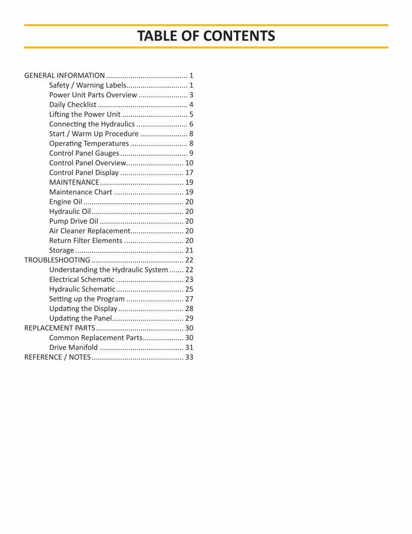
TABLE OF CONTENTS
GENERAL INFORMATION ........................................ 1 Safety / Warning Labels .............................. 1 Power Unit Parts Overview ........................ 3 Daily Checklist ............................................ 4 Lifting the Power Unit ................................ 5 Connecting the Hydraulics ......................... 6 Start / Warm Up Procedure ....................... 8 Operating Temperatures ............................ 8 Control Panel Gauges ................................. 9 Control Panel Overview ............................ 10 Control Panel Display ............................... 17 MAINTENANCE ......................................... 19 Maintenance Chart .................................. 19 Engine Oil ................................................. 20 Hydraulic Oil ............................................. 20 Pump Drive Oil ......................................... 20 Air Cleaner Replacement.......................... 20 Return Filter Elements ............................. 20 Storage ..................................................... 21TROUBLESHOOTING ............................................. 22 Understanding the Hydraulic System ....... 22 Electrical Schematic ................................. 23 Hydraulic Schematic ................................. 25 Setting up the Program ............................ 27 Updating the Display ................................ 28 Updating the Panel ................................... 29REPLACEMENT PARTS ........................................... 30 Common Replacement Parts .................... 30 Drive Manifold ......................................... 31REFERENCE / NOTES ............................................. 33
SPECIFICATIONS
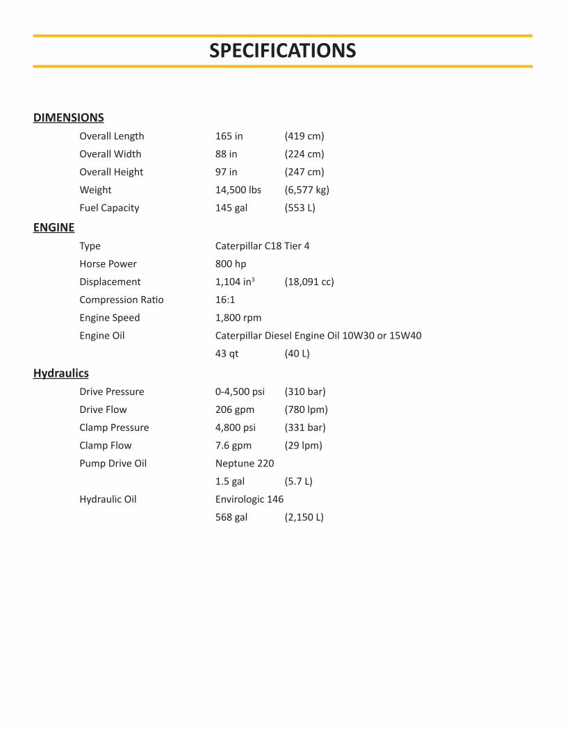
DIMENSIONS Overall Length 165 in (419 cm)
Overall Width 88 in (224 cm)
Overall Height 97 in (247 cm)
Weight 14,500 lbs (6,577 kg)
Fuel Capacity 145 gal (553 L)
ENGINE Type Caterpillar C18 Tier 4
Horse Power 800 hp
Displacement 1,104 in3 (18,091 cc)
Compression Ratio 16:1
Engine Speed 1,800 rpm
Engine Oil Caterpillar Diesel Engine Oil 10W30 or 15W40
43 qt (40 L)
Hydraulics Drive Pressure 0-4,500 psi (310 bar)
Drive Flow 206 gpm (780 lpm)
Clamp Pressure 4,800 psi (331 bar)
Clamp Flow 7.6 gpm (29 lpm)
Pump Drive Oil Neptune 220
1.5 gal (5.7 L)
Hydraulic Oil Envirologic 146
568 gal (2,150 L)
Page 1
GENERAL INFORMATION
Safety / Warning Labels
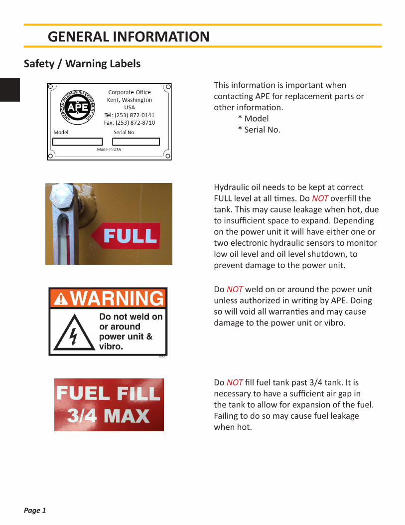
This information is important when contacting APE for replacement parts or other information. * Model * Serial No.
Hydraulic oil needs to be kept at correct FULL level at all times. Do NOT overfill the tank. This may cause leakage when hot, due to insufficient space to expand. Depending on the power unit it will have either one or two electronic hydraulic sensors to monitor low oil level and oil level shutdown, to prevent damage to the power unit.
Do NOT weld on or around the power unit unless authorized in writing by APE. Doing so will void all warranties and may cause damage to the power unit or vibro.
Do NOT fill fuel tank past 3/4 tank. It is necessary to have a sufficient air gap in the tank to allow for expansion of the fuel. Failing to do so may cause fuel leakage when hot.

Page 2
GENERAL INFORMATION
The power unit service record sticker is located on the control panel door and is used to record all service done on the power unit.
Make sure all QD’s are installed and connected completely. Failing to do so may cause damage or prevent proper operation.
Ship with the hydraulic tank forward to prevent damage to the radiator cooling package at the front of the power unit skid.
The daily checklist sticker is located on the control panel door and has a list of everything that needs to be checked on the vibro. Failing to do the daily vibro check may cause damage to the vibro.
Page 3
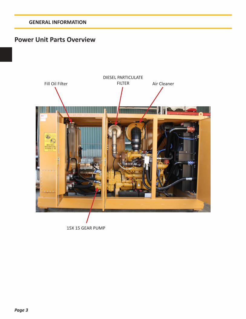
Power Unit Parts Overview
GENERAL INFORMATION
15X 15 GEAR PUMP
Air CleanerFill Oil FilterDIESEL PARTICULATE
FILTER

Page 4
Daily Checklist
Check the entire unit prior to and during set-up each day or at the beginning of each shift
Prior to starting the unit or at the beginning of each shift, check the following:
• Visually inspect all bolts, nuts and screws• Check water level in radiator• Check fuel level• Check oil level in pump drive• Check hydraulic oil level• Check engine oil• Check fan belts on engine• Visually inspect all hydraulic fittings for leaks. If a leak is found or suspected, shutdown the power
unit. If a fitting appears to be damaged, replace with a new fitting.
It is absolutely imperative that no dirt or other impurities be permitted to contaminate the hydraulic fluid. Any contamination will drastically shorten the life of the high-pressure hydraulic system.
Vibration loosens bolts. Check them thoroughly.
GENERAL INFORMATION

Page 5
Always load the power unit with the hydraulic tank facing the front of the truck, to prevent damage to the cooler and radiator from flying debris. When lifting the power unit, position the forklift forks forward as far as possible to prevent load shifts. See Photo.
Lifting the Power Unit
GENERAL INFORMATION
LIFT HERE LIFT HERE
HOIST HERE

Page 6
Connecting the Hydraulics
GENERAL INFORMATION
Drive FWDDrive REVCase DrainClamp Close
Clamp Open

Page 7
CAUTION
While filling the hydraulic lines, the drill motor shaft will rotate.
Please do the following:
• Set the engine at idle• Run at idle for about 10
minutes to fill the lines• Energize ‘Drive Fwd’ - With
the auger, vibro or hydraulic hammer free-hanging will push any remaining air in the lines back to the reservoir.
Pressurizing the system while there is air entrained in the fluid may cause damage to the components.
Let the system run at idle for an additional 10 minutes to allow the air to rise into the airspace of the hydraulic reservoir.
Connecting the hoses is one of the most critical aspects of commissioning APE equipment. Take extreme care to keep these connections absolutely clean. Dirty connections are the most common cause of introducing damaging foreign particles into a hydraulic system.
New hydraulic fluid is NOT clean oil!
Oil must meet ISO cleanliness code 17/15/11
• Connect the hose bundle. Make sure all connections are properly tightened.
• Fill the motor case with clean hydraulic fluid.
GENERAL INFORMATION
Page 8
Operating TemperaturesStart / Warm Up ProcedureBefore operation it is necessary to bring the power unit’s hydraulic oil to a working temperature of 800F. To start and warm up the power unit follow the steps below:
1. On the main control panel, turn main power switch to the ON position.
2. Press and hold engine START/STOP button until engine in running. This should only take a few seconds.
3. Idle power unit in DRIVE until oil temp is above 800F before doing hard work. Failing to do so may cause seal failures, leaks and excessive pressures through the hydraulic system.
GENERAL INFORMATION
The Operating Temperature references the internal temperature of the engine.
Take into consideration the following requirements:
• 70°C (158°F) – Avoid going over this Operating Temperature for improved service life
• 85°C (185°F) – Highest permissible intermittent Operating Temperature
• -35°C (-31°F) – Lowest permissible Operating Temperature
• 60°C (140°F) – Temperature difference between the motor and the hydraulic fluid
The Operating Temperature may be measured from the hydraulic fluid returning from the engine. Take into account the temperature of the hydraulic fluid returning from the case drain line.
Page 9
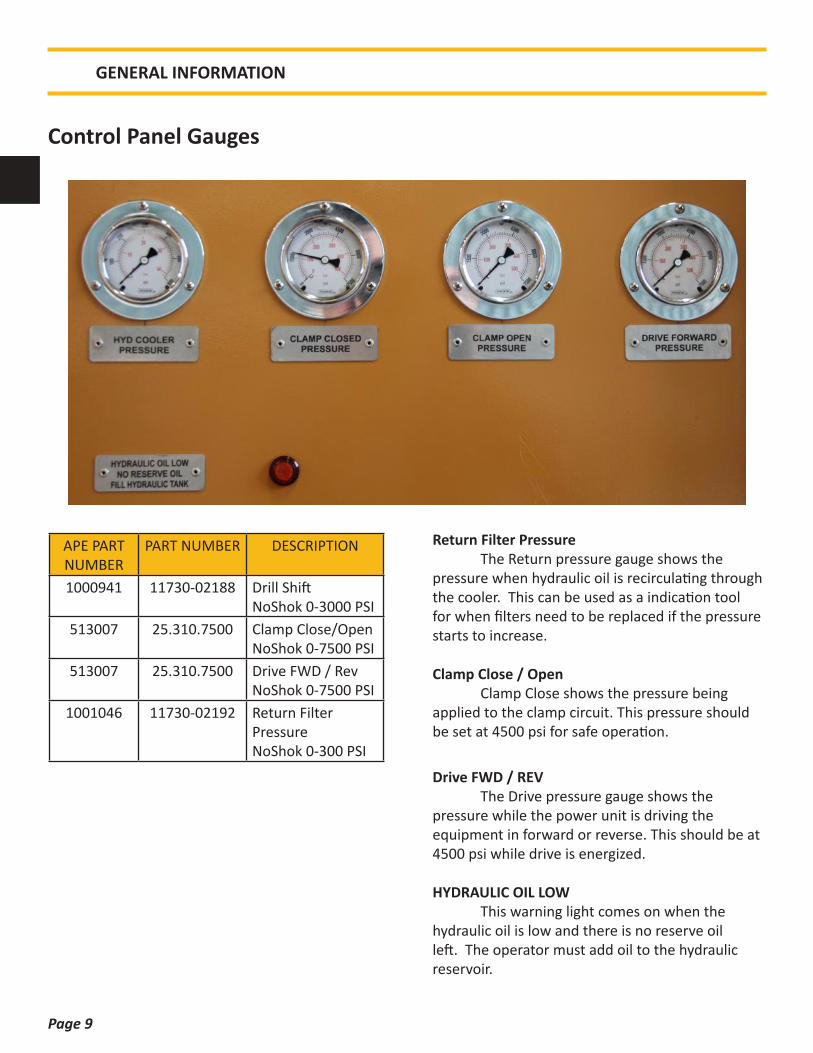
Clamp Close / Open Clamp Close shows the pressure being applied to the clamp circuit. This pressure should be set at 4500 psi for safe operation.
Return Filter Pressure The Return pressure gauge shows the pressure when hydraulic oil is recirculating through the cooler. This can be used as a indication tool for when filters need to be replaced if the pressure starts to increase.
GENERAL INFORMATION
APE PART NUMBER
PART NUMBER DESCRIPTION
1000941 11730-02188 Drill ShiftNoShok 0-3000 PSI
513007 25.310.7500 Clamp Close/OpenNoShok 0-7500 PSI
513007 25.310.7500 Drive FWD / RevNoShok 0-7500 PSI
1001046 11730-02192 Return Filter PressureNoShok 0-300 PSI
Control Panel Gauges
Drive FWD / REV The Drive pressure gauge shows the pressure while the power unit is driving the equipment in forward or reverse. This should be at 4500 psi while drive is energized.
HYDRAULIC OIL LOW This warning light comes on when the hydraulic oil is low and there is no reserve oil left. The operator must add oil to the hydraulic reservoir.

Page 10
Emergency Stop
Speed Hi / Lo
Panel Power
Clamp Close
Drive Fwd
Engine Start / Stop
Panel Cab Pendant
Clamp Open
Drive Rev
Vibro / Drill Mode
Governor
Return to Main Menu
To Select Menu Option
GENERAL INFORMATION
Control Panel Overview

Page 11
LOCAL DISPLAY SCREEN -ENGINE RPM -HYDRAULIC OIL TEMP -HYDRAULIC PRESSURE -DIAGNOSTICS
POWER ON / OFF
This will turn the power on to the control panel. The power must be on to run the unit.
ENGINE START / STOP
If the control panel is powered on this button will fully start the engine. You must hold the button down until the engine fully starts.
To stop the engine, press this button again for a short second. NOTE: Before shutting off the engine, run at 800 RPM idle for at least 1 minute.
The color of the light does not matter.
or
GENERAL INFORMATION

Page 12
CONTROL MODE
ENGINE RPM SPIN RIGHT FOR RPM UP SPIN LEFT FOR RPM DOWN
LED 1 Indicates the control panel can be controlled locally only.
LED 2 Indicates the control panel can be controlled from the remote pendant.
LED 3 Panel can only be controlled from the master control.
This button can only but toggled at the local panel.
EMERGENCY STOP
This can be pressed at any time regardless of what mode the panel is on.Note: Do not use unless emergency.
GENERAL INFORMATION
Page 13
GENERAL INFORMATION
CONTROL MODE
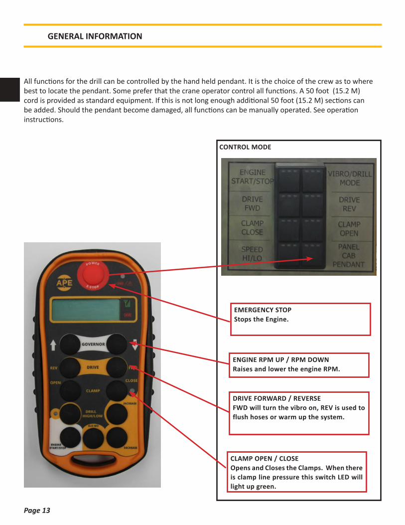
ENGINE RPM UP / RPM DOWNRaises and lower the engine RPM.
DRIVE FORWARD / REVERSEFWD will turn the vibro on, REV is used to flush hoses or warm up the system.
CLAMP OPEN / CLOSEOpens and Closes the Clamps. When there is clamp line pressure this switch LED will light up green.
EMERGENCY STOPStops the Engine.
All functions for the drill can be controlled by the hand held pendant. It is the choice of the crew as to where best to locate the pendant. Some prefer that the crane operator control all functions. A 50 foot (15.2 M) cord is provided as standard equipment. If this is not long enough additional 50 foot (15.2 M) sections can be added. Should the pendant become damaged, all functions can be manually operated. See operation instructions.
Page 14
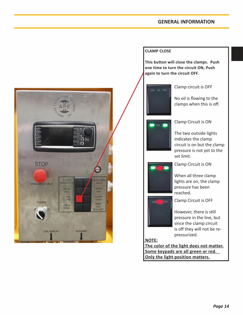
CLAMP CLOSE
This button will close the clamps. Push one time to turn the circuit ON, Push again to turn the circuit OFF.
NOTE: The color of the light does not matter. Some keypads are all green or red. Only the light position matters.
Clamp circuit is OFF
No oil is flowing to the clamps when this is off.
Clamp Circuit is ON
The two outside lights indicates the clamp circuit is on but the clamp pressure is not yet to the set limit.
Clamp Circuit is OFF
However, there is still pressure in the line, but since the clamp circuit is off they will not be re-pressurized.
GENERAL INFORMATION
Clamp Circuit is ON
When all three clamp lights are on, the clamp pressure has been reached.
Page 15
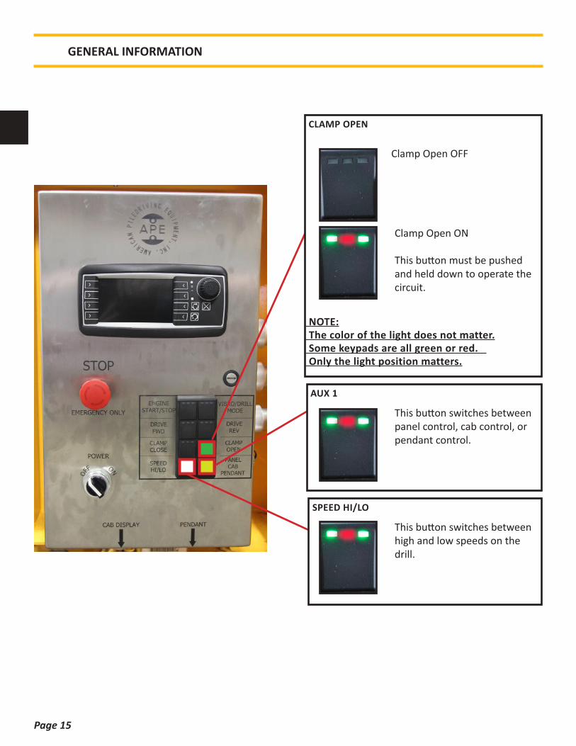
CLAMP OPEN
NOTE: The color of the light does not matter. Some keypads are all green or red. Only the light position matters.
Clamp Open OFF
Clamp Open ON
This button must be pushed and held down to operate the circuit.
SPEED HI/LO This button switches between
high and low speeds on the drill.
AUX 1 This button switches between
panel control, cab control, or pendant control.
GENERAL INFORMATION
Page 16
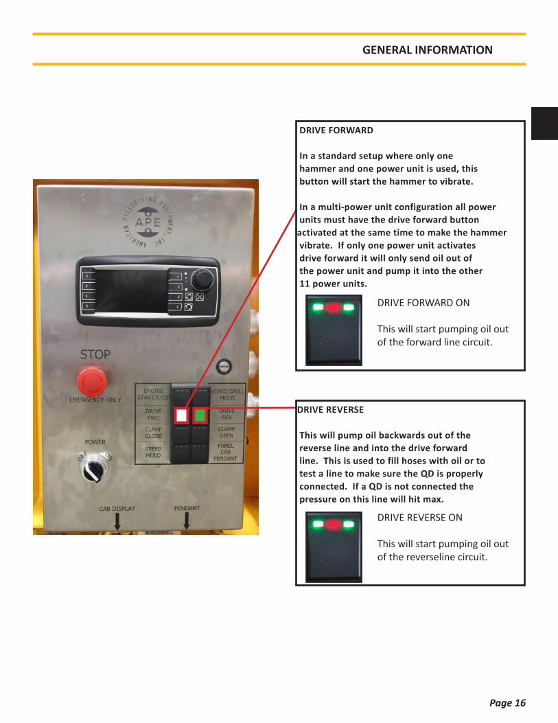
DRIVE REVERSE
This will pump oil backwards out of the reverse line and into the drive forward line. This is used to fill hoses with oil or to test a line to make sure the QD is properly connected. If a QD is not connected the pressure on this line will hit max.
DRIVE REVERSE ON
This will start pumping oil out of the reverseline circuit.
DRIVE FORWARD
In a standard setup where only one hammer and one power unit is used, this button will start the hammer to vibrate.
In a multi-power unit configuration all power units must have the drive forward button activated at the same time to make the hammer vibrate. If only one power unit activates drive forward it will only send oil out of the power unit and pump it into the other 11 power units.
DRIVE FORWARD ON
This will start pumping oil out of the forward line circuit.
GENERAL INFORMATION
Page 17
GENERAL INFORMATION
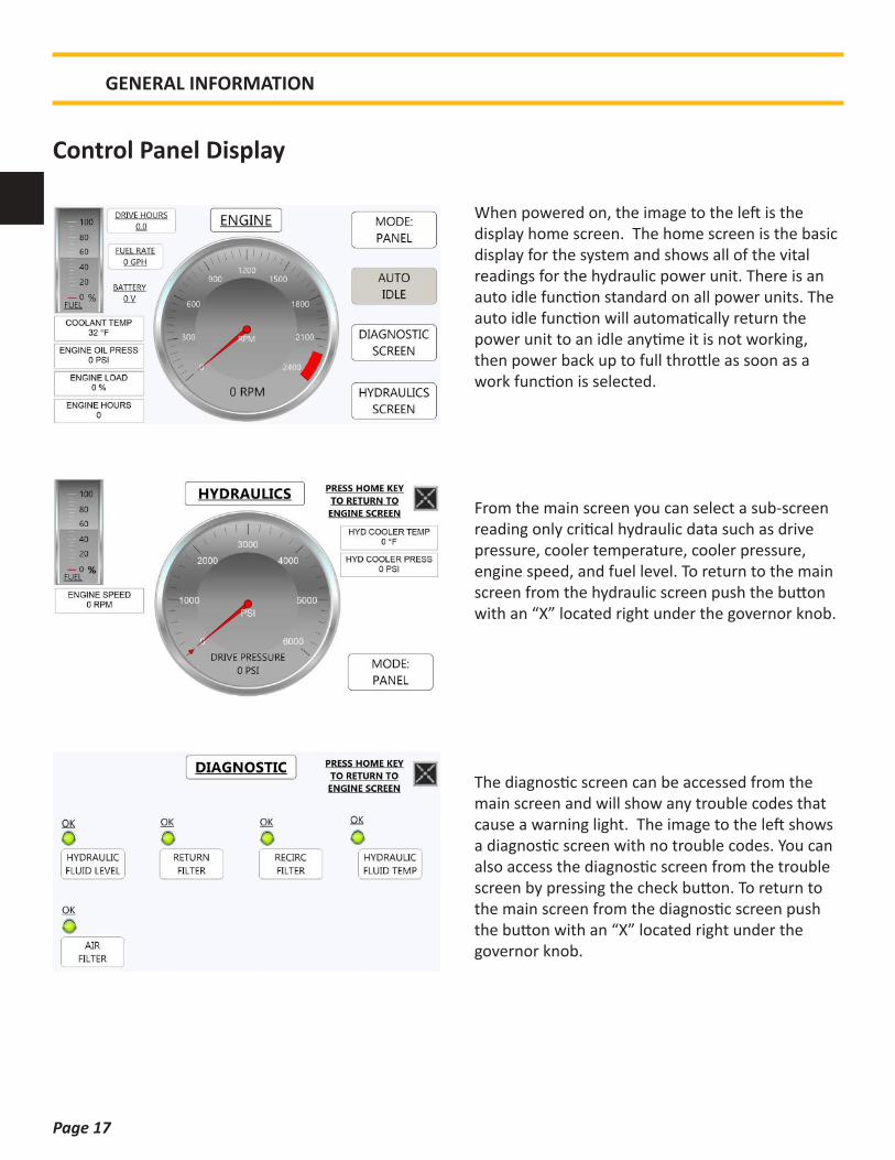
When powered on, the image to the left is the display home screen. The home screen is the basic display for the system and shows all of the vital readings for the hydraulic power unit. There is an auto idle function standard on all power units. The auto idle function will automatically return the power unit to an idle anytime it is not working, then power back up to full throttle as soon as a work function is selected.
From the main screen you can select a sub-screen reading only critical hydraulic data such as drive pressure, cooler temperature, cooler pressure, engine speed, and fuel level. To return to the main screen from the hydraulic screen push the button with an “X” located right under the governor knob.
The diagnostic screen can be accessed from the main screen and will show any trouble codes that cause a warning light. The image to the left shows a diagnostic screen with no trouble codes. You can also access the diagnostic screen from the trouble screen by pressing the check button. To return to the main screen from the diagnostic screen push the button with an “X” located right under the governor knob.
Control Panel Display

Page 18
GENERAL INFORMATION
The setup screens are in a hidden menu that can be accessed by holding down the top left two buttons on the display while turning on the control panel power. Once in the setup screen you can increase or decrease your hydraulic oil temp warnings and your auto idle dwell time. To adjust, simply increase or decrease the selected value, then select SAVE CHANGES. You can also change the equipment from vibro to drill mode depending on the equipment that the power unit will be running. If the settings ever become lost or need to be set back to factory, there is a button on the top left of both setup screens that will reset all panel options back to factory default. To return to the main screen from the setup screen push the button with an “X” located right under the governor knob.
The ERROR screen only appears when there is a trouble code or when one of the sensors fails to send a signal. On the bottom right of the screen the “CHECK“ button will take you to the diagnostic screen where the trouble code can be checked and resolved. To return to the main display screen push the “CHECK” button then the “X” button on the diagnostic screen.
Page 19
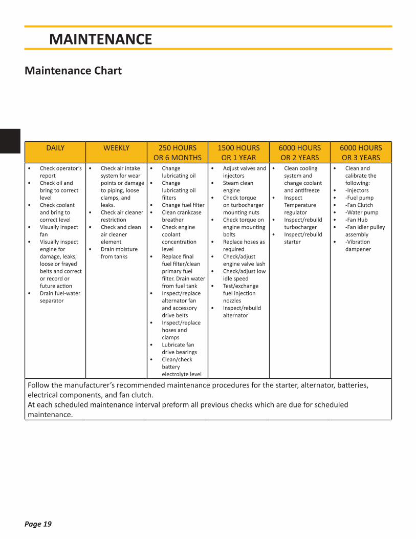
MAINTENANCE
Maintenance Chart
DAILY WEEKLY 250 HOURSOR 6 MONTHS
1500 HOURS OR 1 YEAR
6000 HOURSOR 2 YEARS
6000 HOURSOR 3 YEARS
• Check operator’s report
• Check oil and bring to correct level
• Check coolant and bring to correct level
• Visually inspect fan
• Visually inspect engine for damage, leaks, loose or frayed belts and correct or record or future action
• Drain fuel-water separator
• Check air intake system for wear points or damage to piping, loose clamps, and leaks.
• Check air cleaner restriction
• Check and clean air cleaner element
• Drain moisture from tanks
• Change lubricating oil
• Change lubricating oil filters
• Change fuel filter• Clean crankcase
breather• Check engine
coolant concentration level
• Replace final fuel filter/clean primary fuel filter. Drain water from fuel tank
• Inspect/replace alternator fan and accessory drive belts
• Inspect/replace hoses and clamps
• Lubricate fan drive bearings
• Clean/check battery electrolyte level
• Adjust valves and injectors
• Steam clean engine
• Check torque on turbocharger mounting nuts
• Check torque on engine mounting bolts
• Replace hoses as required
• Check/adjust engine valve lash
• Check/adjust low idle speed
• Test/exchange fuel injection nozzles
• Inspect/rebuild alternator
• Clean cooling system and change coolant and antifreeze
• Inspect Temperature regulator
• Inspect/rebuild turbocharger
• Inspect/rebuild starter
• Clean and calibrate the following:
• -Injectors• -Fuel pump• -Fan Clutch• -Water pump• -Fan Hub• -Fan idler pulley
assembly• -Vibration
dampener
Follow the manufacturer’s recommended maintenance procedures for the starter, alternator, batteries, electrical components, and fan clutch.At each scheduled maintenance interval preform all previous checks which are due for scheduled maintenance.
Page 20
MAINTENANCE
Engine Oil
Hydraulic Oil
Pump Drive Oil
Air Cleaner Replacement
Return Filter Elements
When adding or changing hydraulic fluid, APE uses only Biodegradable Envirologic 146 hydraulic fluid, which is not-toxic and will not harm soil or water, and is biodegradable. Consult your local oil supplier for recommendations on mixing hydraulic oils. Change hydraulic oil if it looks milky; this is an indication that water or other contamination may have occurred.
Check oil level before starting the power unit. The pump drive requires approximately 2 gallons of oil. APE recommends filling the pump drive with Neptune 220 or equivalent when doing oil changes or adding oil. It is recommended to change the pump drive oil every 500 working hours, or 2 years, which ever occurs first.
Change all filters every 500 working hours, 2 years or when indicated dirty, which ever occurs first. To change the return filter element follow the steps below:1. Shut down power unit.2. Place warning tag on control panel so that the
power unit is not started while filters are being replaced.
3. Clean area around filters so that when they are removed there is no chance of introducing dirt into the hydraulic system.
4. Using a 1-1/4 wrench or socket, turn the filter counter-clockwise and spin the filter element off the filter housing.
5. Install new clean filter making sure the spring and o-ring are in the proper place.
Check and clean the air cleaner weekly. If the air cleaner needs to be replaced, use Caterpillar part number 6I-2510.
Change engine oil every 250 hours or 6 months, whichever occurs first. Oil should be replaced with Caterpillar 15W-40 or equivalent oil.
Page 21
Preventative maintenance includes normal servicing that will keep the power unit in peak operative condition and prevent unnecessary trouble from developing. This servicing consists of periodic lubrication and inspection of moving parts and accessories of the unit.
Lubrication is an essential part of preventative maintenance controlling, to a great extent, the useful life of the unit. Different lubricants are needed and some components in the unit require more frequent lubrication than others. Therefore, it is important that the instructions regarding types of lubricants and frequency of their application be closely followed.
To prevent minor irregularities from developing into serious conditions that might involve shutdown and major repair, several other services or inspections are recommended for the same intervals as the periodic lubrications. The purpose of these services or inspections is to assure the uninterrupted operation of the unit.
• Thoroughly clean all lubrication fittings, caps, filler and level plugs along with their surrounding surfaces before servicing
• Prevent dirt from entering in with lubricants and coolants
The intervals given in the schedule are based upon normal operation.
Perform these services, inspections, etc., more often as needed for operation under abnormal or severe conditions.
Storage
During short-term storage of a power unit, the following should be taken into consideration:
• Cover any pressure openings and open threaded holes with suitable caps
• Protect the unpainted surfaces from dirt and moisture
• The power unit should not be stored in an area with substances that have an aggressive corrosive nature; i.e., solvents, acids, alkalies and/or salts
For long-term storage (over 9 months), the following additional actions are recommended:
• Damages to surface paint must be repaired before item is stored
• Protect the unpainted surfaces with suitable anti-corrosion treatment such as CRC SP-350, CorrosionX corrosion inhibitor, or WD-40 Long Term Corrosion Inhibitor
• Fill the power unit completely with hydraulic fluid
If these instructions are followed to the letter, the power unit may be stored for approximately 2-years. However, as storage conditions do have a significant effect, all suggested time frames should be considered as guide values only.
MAINTENANCE
Page 22
TROUBLESHOOTING
• Pressure filters: Clean the hydraulic fluid going to the drill motor and manifold in the forward and reverse directions.
• M1/M2 DRIVE• LS LOAD SENSE• 10/11: RDFA-LCN is a direct acting relief valve
that is used to protect hydraulic components from pressure variants.
• 8/16/5/19 COILS• T1 / PD: Both of these ports return to tank.
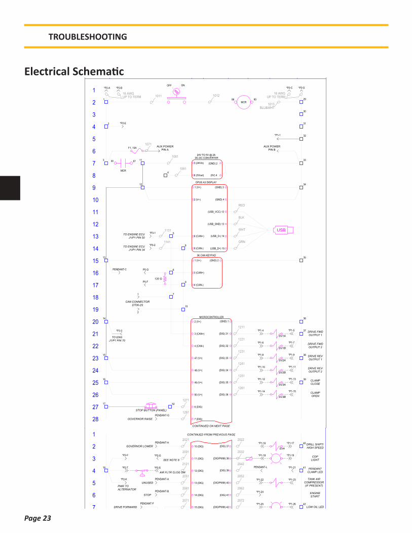
Electrical System
The electrical system is a normally closed circuit, and runs a self diagnostic test when the panel is powered on. If there is a fault in the electrical system an error screen will appear on the control panel display.
It is imperative that the hydraulic fluid is kept clean to a minimum ISO Code
17/15/11New hydraulic fluid is NOT clean oil
*See attached document “Understanding ISO Codes” under the Reference / Notes Section*
*See Warranty document regarding fluid cleanliness at the beginning of this manual*
Bulk oil does not typically meet the cleanliness standards required by APE equipment.
Understanding the Hydraulic System
Page 23
Electrical Schematic
TROUBLESHOOTING
(0V) 4
(GND) 2
DC-DC CONVERTER
3 (24Vin)
6 (5Vout)
24V TO 5V @ 2A
OFF ON
86 85
30 87
F1, 10A
28
27
1
3
5
7
9
11
13
15
17
19
21
23
25
2
4
6
8
10
12
14
16
18
20
22
24
26
DRILL/VIBRO CONTROL PANEL ELECTRICAL SCHEMATIC
019123 ABY THP DATE 1/26/18
SCALE N/A
-N/A-AMERICAN PILEDRIVING EQUIPMENT PREV. J/N
CHK SHT
OF 31
Portland, Oregon
REV
HYDRA-POWER SYSTEMS, INC.HYDRA-POWER SYSTEMS, INC.C
===== PROPRIETARY NOTICE =====THIS DRAWING, SKETCH OR TEXT CONTAINSCONCEPTS, DESIGNS, PRODUCTS AND INFORMATIONTHAT IS PROPRIETARY TO HYDRA-POWER SYSTEMS,INC. AND MAY NOT BE REPRODUCED OR GIVEN TO ATHIRD PARTY WITHOUT THE WRITTEN CONSENT OFHYDRA-POWER SYSTEMS, INC.
2018
XXXX
WIRE NO.LINE NO.SHEET NO.
WIRE NUMBER SYSTEM
CUSTOMER J/N REF. #
MCR
MCR
AUX POWERPIN A
AUX POWERPIN B
(GND) 12 (V+)MICROCONTROLLER
47 (V+)
48 (V+)
49 (V+)
50 (V+)
(GND) 3
OPUS A3 DISPLAY
1 (V+)
8 (CAN+)
2 (V+) (GND) 4
9 (CAN-)
(GND) 2
3K CAN KEYPAD
1 (V+)
3 (CAN+)
4 (CAN-)
CONTINUED ON NEXT PAGE
3 (CAN+)
4 (CAN-)
*P3-1
*P3-2
120 Ω
(DIG) 31
(DIG) 32
(DIG) 33
(DIG) 34
(DIG) 35
(DIG) 36
PENDANT-G
PENDANT-C
1
2
3
4
5
8
6
9
*P1-1
1011
BLU&WHT
1012
TO ENGINE ECUJ1/P1 PIN 50
TO ENGINE ECUJ1/P1 PIN 34
1071
1081
1091
1131
1141
1211
1221
1231
1241
1251
1261
*P2-A *P2-D
1013
*P2-B *P2-C
16 AWGUP TO TERM
16 AWGUP TO TERM
*P3-3
TO ENGJ1/P1 PIN 70
*P2-E
6 (DIG)
7 (DIG)
1271
1281
7
10
STOP BUTTON (PANEL)
CLAMPCLOSE
CLAMPOPEN
*P1-4 *P1-5
*P1-6 *P1-7
*P1-8 *P1-9
*P1-10 *P1-11
*P1-12 *P1-13
*P1-14 *P1-15
13
14
15
16
17
12
11
29
32
33
34
35
36
37
38
39
SV1A
SV3A
SV3B
CAN CONNECTORDT06-2S
1
2
GOVERNOR RAISE
30
31
P5-G
P5-F
(USB_VCC) 12
(USB_GND) 13
(USB_D-) 14
(USB_D+) 15
USB
RED
BLK
WHT
GRN
52
SV2A
SV1B
SV2B
DRIVE FWDOUTPUT 1
DRIVE FWDOUTPUT 2
DRIVE REVOUTPUT 1
DRIVE REVOUTPUT 2
28
27
1
3
5
7
9
11
13
15
17
19
21
23
25
2
4
6
8
10
12
14
16
18
20
22
24
26
BY THP
SCALE N/A
-N/A-AMERICAN PILEDRIVING EQUIPMENT PREV. J/N
CHK SHT
OF 32
Portland, Oregon
REV
HYDRA-POWER SYSTEMS, INC.HYDRA-POWER SYSTEMS, INC.C
===== PROPRIETARY NOTICE =====THIS DRAWING, SKETCH OR TEXT CONTAINSCONCEPTS, DESIGNS, PRODUCTS AND INFORMATIONTHAT IS PROPRIETARY TO HYDRA-POWER SYSTEMS,INC. AND MAY NOT BE REPRODUCED OR GIVEN TO ATHIRD PARTY WITHOUT THE WRITTEN CONSENT OFHYDRA-POWER SYSTEMS, INC.
2018
XXXX
WIRE NO.LINE NO.SHEET NO.
WIRE NUMBER SYSTEM
CUSTOMER J/N REF. #
(DIG) 37
CONTINUED FROM PREVIOUS PAGE
10 (DIG)
11 (DIG)
12 (DIG)
13 (DIG)
14 (DIG)
15 (DIG)
16 (AN/DIG)
17 (AN/DIG)
18 (AN/DIG)
19 (AN/DIG)
22 (AN/DIG)
25 (AN/DIG)
28 (AN/DIG)
(DIG/PWM) 38
(DIG) 39
(DIG/PWM) 40
(DIG) 41
PENDANT-H
PENDANT-J
PENDANT-K
PENDANT-A
PENDANT-B
DRILL SHIFT/HIGH SPEED
POWER FORCAT ET ACCESS
GROUND FORCAT ET ACCESS
2021
2031
2041
2051
2061
2071
2081
2091
2121
2111
2131
2141
2151
2181
2211
2022
2032
2042
2052
2062
(DIG/PWM) 42
2072
(DIG/PWM) 43
2082
(DIG/PWM) 44
2092
(DIG/PWM) 45
2102
27 (AN/DIG)
2201
(DIGPWM) 46
2112
PENDANT-M
PENDANT-F
PENDANT-E
23 (AN/DIG)
24 (AN/DIG)
ENGINESTART
30 (AN/DIG)
224126 (AN/DIG)
2231
COPLIGHT
PENDANTCLAMP LED
TANK AIRCOMPRESSOR(IF PRESENT)
LOW OIL LED
FAN VALVE
UNUSEDOUTPUT
UNUSEDOUTPUT
UNUSEDOUTPUT
FUEL LEVEL
*P2-F *P2-G
*P2-H *P2-J
*P2-L
*P2-M *P2-N
*P2-O *P2-P
*P2-Q *P2-R
*P3-10 *P3-12
*P3-13 *P3-16
*P3-15 *P3-17
*P3-18
*P3-20*P3-21
*P3-22
*P1-16 *P1-17
*P1-18 *P1-19
*P1-21
*P1-22 *P1-23
*P1-24
*P1-25 *P1-26
*P1-27 *P1-28
*P1-29 *P1-30
*P3-6 *P3-7
*P3-8
*P3-9
*P3-11
*P3-14
18
19
20
21
22
23
24
25
26
40
41
42
43
44
45
46
47
48
49
SV4GOVERNOR LOWER
CLAMP OPEN
CLAMP CLOSE/ HIGH SPEED
UNUSED
STOP
DRIVE FORWARD
DRIVE REVERSE
(SIG)
(GND)(24Vin)
FUEL LEVEL SENSOR
RED BLK
WHT
*P3-19
29 (AN/DIG)2101
AIR FLTR CLOG SW
*P2-S*P2-T
P5-A
P5-B
PENDANT-L
DRILL/VIBRO CONTROL PANEL ELECTRICAL SCHEMATIC
*P2-K
SEE NOTE 8
SEE NOTE 8
SEE NOTE 8
SEE NOTE 8
SEE NOTE 8
SEE NOTE 8
SEE NOTE 8
SEE NOTE 8
SEE NOTE 8
PWR TOALTERNATOR
SEE NOTE 8
680 Ω
680 Ω
680 Ω
680 Ω
019123 ADATE 1/26/18
CAT DATA LINK+
CAT DATA LINK-
TO ENGINE ECUJ1/P1 PIN 8
TO ENGINE ECUJ1/P1 PIN 9
2271
2281
*P3-4
*P3-5
50
51
P5-D
P5-E

Page 24
TROUBLESHOOTING
28
27
1
3
5
7
9
11
13
15
17
19
21
23
25
2
4
6
8
10
12
14
16
18
20
22
24
26
BY THP
SCALE N/A
-N/A-AMERICAN PILEDRIVING EQUIPMENT PREV. J/N
CHK SHT
OF 32
Portland, Oregon
REV
HYDRA-POWER SYSTEMS, INC.HYDRA-POWER SYSTEMS, INC.C
===== PROPRIETARY NOTICE =====THIS DRAWING, SKETCH OR TEXT CONTAINSCONCEPTS, DESIGNS, PRODUCTS AND INFORMATIONTHAT IS PROPRIETARY TO HYDRA-POWER SYSTEMS,INC. AND MAY NOT BE REPRODUCED OR GIVEN TO ATHIRD PARTY WITHOUT THE WRITTEN CONSENT OFHYDRA-POWER SYSTEMS, INC.
2018
XXXX
WIRE NO.LINE NO.SHEET NO.
WIRE NUMBER SYSTEM
CUSTOMER J/N REF. #
(DIG) 37
CONTINUED FROM PREVIOUS PAGE
10 (DIG)
11 (DIG)
12 (DIG)
13 (DIG)
14 (DIG)
15 (DIG)
16 (AN/DIG)
17 (AN/DIG)
18 (AN/DIG)
19 (AN/DIG)
22 (AN/DIG)
25 (AN/DIG)
28 (AN/DIG)
(DIG/PWM) 38
(DIG) 39
(DIG/PWM) 40
(DIG) 41
PENDANT-H
PENDANT-J
PENDANT-K
PENDANT-A
PENDANT-B
DRILL SHIFT/HIGH SPEED
POWER FORCAT ET ACCESS
GROUND FORCAT ET ACCESS
2021
2031
2041
2051
2061
2071
2081
2091
2121
2111
2131
2141
2151
2181
2211
2022
2032
2042
2052
2062
(DIG/PWM) 42
2072
(DIG/PWM) 43
2082
(DIG/PWM) 44
2092
(DIG/PWM) 45
2102
27 (AN/DIG)
2201
(DIGPWM) 46
2112
PENDANT-M
PENDANT-F
PENDANT-E
23 (AN/DIG)
24 (AN/DIG)
ENGINESTART
30 (AN/DIG)
224126 (AN/DIG)
2231
COPLIGHT
PENDANTCLAMP LED
TANK AIRCOMPRESSOR(IF PRESENT)
LOW OIL LED
FAN VALVE
UNUSEDOUTPUT
UNUSEDOUTPUT
UNUSEDOUTPUT
FUEL LEVEL
*P2-F *P2-G
*P2-H *P2-J
*P2-L
*P2-M *P2-N
*P2-O *P2-P
*P2-Q *P2-R
*P3-10 *P3-12
*P3-13 *P3-16
*P3-15 *P3-17
*P3-18
*P3-20*P3-21
*P3-22
*P1-16 *P1-17
*P1-18 *P1-19
*P1-21
*P1-22 *P1-23
*P1-24
*P1-25 *P1-26
*P1-27 *P1-28
*P1-29 *P1-30
*P3-6 *P3-7
*P3-8
*P3-9
*P3-11
*P3-14
18
19
20
21
22
23
24
25
26
40
41
42
43
44
45
46
47
48
49
SV4GOVERNOR LOWER
CLAMP OPEN
CLAMP CLOSE/ HIGH SPEED
UNUSED
STOP
DRIVE FORWARD
DRIVE REVERSE
(SIG)
(GND)(24Vin)
FUEL LEVEL SENSOR
RED BLK
WHT
*P3-19
29 (AN/DIG)2101
AIR FLTR CLOG SW
*P2-S*P2-T
P5-A
P5-B
PENDANT-L
DRILL/VIBRO CONTROL PANEL ELECTRICAL SCHEMATIC
*P2-K
SEE NOTE 8
SEE NOTE 8
SEE NOTE 8
SEE NOTE 8
SEE NOTE 8
SEE NOTE 8
SEE NOTE 8
SEE NOTE 8
SEE NOTE 8
PWR TOALTERNATOR
SEE NOTE 8
680 Ω
680 Ω
680 Ω
680 Ω
019123 ADATE 1/26/18
CAT DATA LINK+
CAT DATA LINK-
TO ENGINE ECUJ1/P1 PIN 8
TO ENGINE ECUJ1/P1 PIN 9
2271
2281
*P3-4
*P3-5
50
51
P5-D
P5-E
NOTES:
1) CONNECTIONS BETWEEN TERMINALS TO BE HARD JUMPERS UNLESS OTHERWISE INDICATED.
2) REFER TO LAYOUT DRAWING FOR LOCATIONS OF CONNECTORS 'P1', 'P2', 'P3', 'P4', 'AUX POWER',AND 'PENDANT'.
3) DASHED ELECTRICAL WIRE LINES INDICATE WIRING EXTERNAL TO THE ELECTRICAL BOX ANDNOT PART OF THIS ASSEMBLY.
4) ALL WIRES TO BE BLUE 18 OR 20 AWG UNLESS OTHERWISE INDICATED.
5) ALL UNUSED POSITIONS IN BULKHEAD CONNECTORS TO BE PLUGGED WITH DEUTSCH SEALINGPLUGS.
6) CONNECTOR P5 TO HANG LOOSE (WITH DUST CAP) INSIDE ENCLOSURE. USE CABLE ANCHOR TOSECURE CONNECTOR TO INNER SIDE OF ENCLOSURE. CONNECTOR PART NUMBER ISHD14-9-96P.
7) PINS WITH AN ASTERISK (*) ARE INCLUDED IN WIRE HARNESS TO EITHER A BULKHEADCONNECTOR OR FLYING LEADS.
8) USE WITH DANFOSS SERVICE TOOL 018394.p1d TO SELECT SENSORS FOR INPUTS 17, 18, 19, 22,23, 24, 25, 27, 28, AND 30
1
3
5
7
9
11
13
15
17
19
21
23
25
2
4
6
8
10
12
14
16
18
20
22
24
26
BY THP
SCALE N/A
-N/A-AMERICAN PILEDRIVING EQUIPMENT PREV. J/N
CHK SHT
OF 33
Portland, Oregon
REV
HYDRA-POWER SYSTEMS, INC.HYDRA-POWER SYSTEMS, INC.C
===== PROPRIETARY NOTICE =====THIS DRAWING, SKETCH OR TEXT CONTAINSCONCEPTS, DESIGNS, PRODUCTS AND INFORMATIONTHAT IS PROPRIETARY TO HYDRA-POWER SYSTEMS,INC. AND MAY NOT BE REPRODUCED OR GIVEN TO ATHIRD PARTY WITHOUT THE WRITTEN CONSENT OFHYDRA-POWER SYSTEMS, INC.
2018
XXXX
WIRE NO.LINE NO.SHEET NO.
WIRE NUMBER SYSTEM
CUSTOMER J/N REF. #
REV.'A' - INITIAL RELEASE PER THP 1/26/18
DRILL/VIBRO CONTROL PANEL ELECTRICAL SCHEMATIC
CAT DATA LINK+
CAT DATA LINK-
TO ENGINE ECUJ1/P1 PIN 8
TO ENGINE ECUJ1/P1 PIN 9
2271
2281
*P3-4
*P3-5
50
51
P5-D
P5-E
019123 ADATE 1/26/18
Page 25
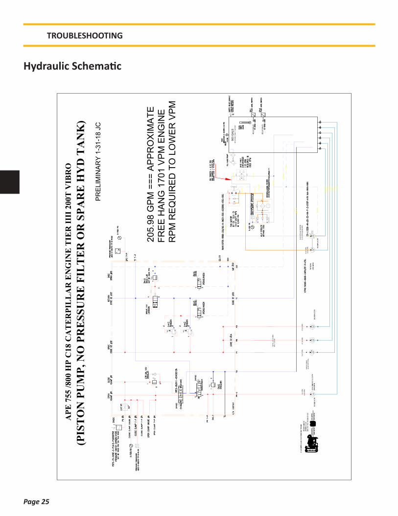
Hydraulic Schematic
9.6
GP
M
SA
E 3
2
SA
E 3
2
SA
E 2
0
SA
E 2
0
112 (
61
)11
2 (
61
)
BY
PA
SS
SA
E 2
4
CO
LL
ER
SA
E 2
4
1 1
/4"
HO
SE
1 1
/4"
HO
SE
2"
HO
SE
2"
HO
SE
2"
HO
SE
1 1
/4"
HO
SE
1 1
/4"
HO
SE
1 1
/4"
(62)
1 1
/4"
SA
E
2 1
/2"
(61)
1/2
" H
OS
E
54.6
5 G
PM
@ 1
566 R
PM
563 G
ALS
40
.0 G
AL
S
80
.0 G
AL
S
3"
(61
)
75.6
7 G
PM
34"
HO
SE
1.1 CIR
10.9
8C
IR
7.9
3C
IR
2"
HO
SE
2"
HO
SE
2"
HO
SE
114"
HO
SE
3"
HO
SE
21
2"
HO
SE
1"
HO
SE
114"
HO
SE
75.6
7 G
PM
TO
TA
L 2
10.1
9 G
PM
98%
= 2
05.9
8
34"
HO
SE
2"
HO
SE
23.3
5 G
PM
@ 6
96 R
PM
33.6
0 G
PM
PR
EL
IMIN
AR
Y 1
-31
-18 J
C
A
PE
755
/8
00
HP
C18
CA
TE
RP
ILL
AR
EN
GIN
E T
IER
III
I 20
0T V
IBR
O
(PIS
TO
N P
UM
P, N
O P
RE
SS
UR
E F
ILT
ER
OR
SP
AR
E H
YD
TA
NK
)
NO
SP
AR
E T
AN
K 7
" A
IR G
AP
PU
MP
DR
IVE
4PD
08
1:1.
13D
11-C
C-C
C-C
CH
-CC
-LS
CA
TE
RP
ILL
AR
C18
TIE
R I
III
755/
800
1800
RP
MA
UX
DR
IVE
1:1
.2 C
W21
60 R
PM
10.9
8C
IR
DR
IVE
CU
BE
S32.9
4 C
IR T
OT
AL
PU
MP
CC
WP
UM
PS
CC
W
PU
MP
S C
CW
800
RP
M
1592
RP
M
707
RP
M9.7
6C
IR9.7
6C
IR15
92 R
PM
707
RP
M
67.2
6 G
PM
67.2
6 G
PM
20
5.9
8 G
PM
==
= A
PP
RO
XIM
AT
EF
RE
E H
AN
G 1
70
1 V
PM
EN
GIN
ER
PM
RE
QU
IRE
D T
O L
OW
ER
VP
M
4.2
6 G
PM
TROUBLESHOOTING
Page 26
SA
E 3
2
SA
E 3
2
SA
E 2
0
SA
E 2
0
112 (
61
)11
2 (
61
)
BY
PA
SS
SA
E 2
4
CO
LL
ER
SA
E 2
4
1 1
/4"
HO
SE
1 1
/4"
HO
SE
2"
HO
SE
2"
HO
SE
2"
HO
SE
1 1
/4"
HO
SE
1 1
/4"
HO
SE
1 1
/4"
(62)
1 1
/4"
SA
E
2 1
/2"
(61)
1/2
" H
OS
E
61.7
9 G
PM
@ 1
800 R
PM
563 G
ALS
40
.0 G
AL
S
80
.0 G
AL
S
3"
(61
)
76
.05
GP
M
34"
HO
SE
5.4
CIR
1.1 CIR
9.7
6C
IR
7.9
3C
IR
2"
HO
SE
2"
HO
SE
2"
HO
SE
11
4"
HO
SE
3"
HO
SE
21
2"
HO
SE
1"
HO
SE
11
4"
HO
SE
70.1
2 G
PM
70.1
2 G
PM
77.1
4 G
PM
TO
TA
L 2
17.3
8 G
PM
95%
= 2
06.5
1
34"
HO
SE
2"
HO
SE
25.7
4 G
PM
@ 7
50 R
PM
31.6
8 G
PM
PR
ELIM
INA
RY
1-3
1-1
8 J
C
AP
E 7
55 /
80
0 H
P C
18
CA
TE
RP
ILL
AR
EN
GIN
E T
IER
III
I 20
0T V
IBR
O
(GE
AR
PU
MP
, N
O P
RE
SS
UR
E F
ILT
ER
OR
SP
AR
E H
YD
TA
NK
)
NO
SP
AR
E T
AN
K 7
" A
IR G
AP
PU
MP
DR
IVE
4P
D08
1:1
D1
1-C
C4
5-C
C4
5-C
CH
-CC
45-L
S
CA
TE
RP
ILL
AR
C18
TIE
R I
III
755
/800
180
0 R
PM
AU
X D
RIV
E 1
:1.2
CW
2160
RP
M
20
6.5
1 G
PM
==
= A
PP
RO
XIM
AT
EF
RE
E H
AN
G 1
70
6 V
PM
EN
GIN
ER
PM
RE
QU
IRE
D T
O L
OW
ER
VP
M
4.5
CIR
4.5
CIR
4.5
CIR
4.5
CIR
4.5
CIR
DR
IVE
CU
BE
S27.9
CIR
TO
TA
L
PU
MP
CC
WP
UM
PS
CC
WP
UM
PS
CC
W
3 1
2 X
12
16
50
VP
M
750
RP
M
180
0 R
PM
750
RP
M
9.6
GP
M
4.0
0 G
PM
TROUBLESHOOTING

Page 27
Prior to any program updates you will need:1. A blank flash drive2. A laptop with Plus + One Service
guide software installed http://www2.powersolutions.danfoss.com/l/38972/2016-05-30/525qvt
3. CAN to USB adapter
To update the program you must first download and format the flash drive as follows:
1. Insert blank USB into your laptop.a. Format USB by going to:b. My computerc. Right click on flash drived. Click on format and format as shown in
the figure to the right.2. Download all files from link provided3. Extract all downloaded files onto USB drive.4. All files in the folder labeled “Display
Program” must be moved out of the folder or the update will not work.
5. On the bottom right of the screen eject USB to prevent any file corruption.
Setting up the Program
TROUBLESHOOTING

Page 28
Updating the DisplayTo load the program onto the display from the USB drive follow steps below:
1. Make sure main power on the panel is turned off.
2. Open panel and plug-in USB drive into plug on the inside of the panel cover.
3. Hold down the top left two buttons on the display and turn on the main power. Continue to hold the two buttons down until the blue maintenance screen pops up on the display.
4. The display will auto update and count down from 15 and auto restart.
5. Wait 60 seconds then turn off main power and remove the USB drive.
6. Close the panel. Power-on to verify the update was successfully installed.
PRESSHERE
TROUBLESHOOTING
Page 29
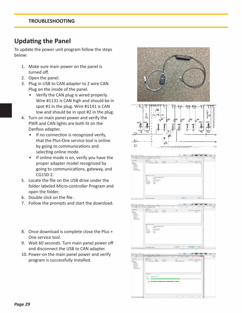
Updating the Panel
TROUBLESHOOTING
To update the power unit program follow the steps below:
1. Make sure main power on the panel is turned off.
2. Open the panel.3. Plug in USB to CAN adapter to 2 wire CAN
Plug on the inside of the panel.• Verify the CAN plug is wired properly.
Wire #1131 is CAN high and should be in spot #1 in the plug. Wire #1141 is CAN low and should be in spot #2 in the plug.
4. Turn on main panel power and verify the PWR and CAN lights are both lit on the Danfoss adapter.• If no connection is recognized verify,
that the Plus-One service tool is online by going to communications and selecting online mode.
• If online mode is on, verify you have the proper adapter model recognized by going to communications, gateway, and CG150-2.
5. Locate the file on the USB drive under the folder labeled Micro-controller Program and open the folder.
6. Double click on the file .7. Follow the prompts and start the download.
8. Once download is complete close the Plus + One service tool.
9. Wait 60 seconds. Turn main panel power off and disconnect the USB to CAN adapter.
10. Power-on the main panel power and verify program is successfully installed.

Page 30
REPLACEMENT PARTS
Common Replacement Parts
FILTERSLOCATION ENGINE PART NUMBER APE PART NUMBER QUANTITY
Engine Oil Filter C18 1R-1808 521033 1Engine Fuel/Water Separator C18 326-1643 555131 1Engine Fuel Filter C18 1R-0751 555129 1Air Filter C18 130-4678 Outer 130-4679 Inner 1Return Filter C18 KKZ25 1000586 2
FLUID CAPACITYLOCATION ENGINE OIL TYPE APE PART NUMBER CAPACITY
Engine Oil C18 Caterpillar DELO 15W-40 513001-15W40-D400-1 17 qt (16L)Engine Coolant C18 Caterpillar DEAC Antifreeze 513001-ANTI-A DEAC-1Pump Drive C18 Neptune 220 Arctic Gear Oil 513001S-A NEP220 6 qt (5.7L)Fuel C18 Diesel Fuel 145 gal (553L)Hydraulic Oil C18 Envirological 146 513001 568 gal (2,150L)
MISC ITEMSDESCRIPTION ENGINE PART NUMBER APE PART NUMBER
Battery C18 Group Size 4D 541009Fan Belt C18 2M-8183 DFAlternator Belt C18 9L4896Water Pump Belt C18 9L-4896 DFHydraulic Sight Gauge 6” G607-06-A-1-4-513003Hydraulic Sight Gauge 30” G607-30-A-1 1/2-513003Hydraulic Level Sensor b40040AFD2C758/6amp 1006759Hydraulic Tank BreatherFuel Level Gauge 8680-010255 513050
SENSORSDESCRIPTION PART NUMBER APE PART NUMBER QUANTITY
Fuel Level Sensor 1Hydraulic Level Sensor 1Drive Pressure Transducer 3202H60CPS1P8R00 1005409 1Cooler Bypass Transducer 3202H500PG1P8R00 1005295 1Schroeder Indicator Sending Unit MS19TNC-50 1003577 2

Page 31
REPLACEMENT PARTS
Drive Manifold
CALLOUT PART # DESCRIPTION QTY
1 1007251 VIBRO DRIVE MANIFOLD 12 CBCG-LJN COUNTERBALANCE VALVE 13 RPEC-LAN PISTON RELIEF VALVE 24 LOKA-XDN VENT TO OPEN POPPET 15 RVIS-LAN POPPET RELIEF VALVE 26 DTDA-SCN SOFT SHIFT SOLENOID 27 DMDM-LAN DIRECTIONAL SPOOL VALVE 18 770-924 24V DC COIL 29 6400-04-06 ORB-JIC REDUCER 3
10 6408-06 HEX PLUG 1311 6408-08 HEX PLUG 212 EPCO 06 EPCO HEX PLUG 313 EPCO 16 EPCO HEX PLUG 314 XIOA-XXN CAVITY PLUG 3
Page 32
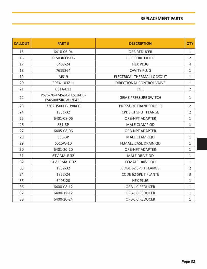
CALLOUT PART # DESCRIPTION QTY
15 6410-06-04 ORB REDUCER 116 KC503KXXSD5 PRESSURE FILTER 217 6408-24 HEX PLUG 418 7619264 CAVITY PLUG 119 MS19 ELECTRICAL THERMAL LOCKOUT 120 RPE4-103Z11 DIRECTIONAL CONTROL VALVE 121 C31A-E12 COIL 2
22 PS75-70-4MSZ-C-FLS18-DE-FS4500PSIR-W126435 GEMS PRESSURE SWITCH 1
23 3202H500PG1P8R00 PRESSURE TRANDSDUCER 224 1951-32 CPDE 61 SPLIT FLANGE 225 6401-08-06 ORB-NPT ADAPTER 126 S31-3P MALE CLAMP QD 127 6405-08-06 ORB-NPT ADAPTER 128 S35-3P MALE CLAMP QD 129 S515W-10 FEMALE CASE DRAIN QD 130 6401-20-20 ORB-NPT ADAPTER 131 6TV MALE 32 MALE DRIVE QD 132 6TV FEMALE 32 FEMALE DRIVE QD 133 1952-32 CODE 62 SPLIT FLANGE 234 1952-24 CODE 62 SPLIT FLANTE 335 6408-20 HEX PLUG 136 6400-08-12 ORB-JIC REDUCER 137 6400-12-12 ORB-JIC REDUCER 138 6400-20-24 ORB-JIC REDUCER 1
REPLACEMENT PARTS
Page 33
REFERENCE / NOTES
UNDERSTANDING ISO CODES
×ÍÑ ììðê ݸ¿®¬
ݱ¼» Ó±®» ¬¸¿² Ë° ¬±ñ·²½´«¼·²¹
îì èðððð ïêðððð
îí ìðððð èðððð
îî îðððð ìðððð
îï ïðððð îðððð
îð ëððð ïðððð
ïç îëðð ëððð
ïè ïíðð îëðð
ïé êìð ïíðð
ïê íîð êìð
ïë ïêð íîð
ïì èð ïêð
ïí ìð èð
ïî îð ìð
ïï ïð îð
ïð ë ïð
ç îòë ë
è ïòí îòë
é ðòêì ïòí
ê ðòíî ðòêì
ﮬ·½´» Í·¦»
ﮬ·½´» °»® ³´ö
×ÍÑ ììðê ݱ¼» ®¿²¹»
×ÍÑ Ý±¼»
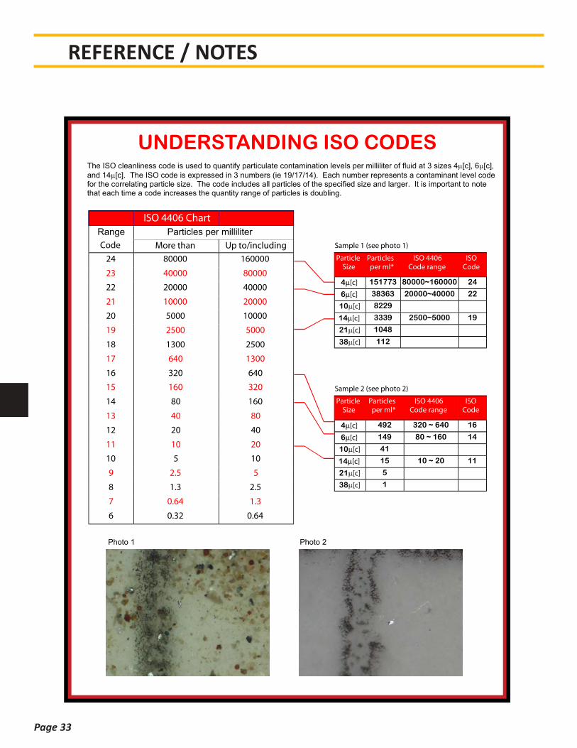
4 Žà 151773 80000~160000 24
6 Žà 38363 20000~40000 22
10 Žà 8229
14 Žà 3339 2500~5000 19
21 Žà 1048
38 Žà 112
ﮬ·½´» Í·¦»
ﮬ·½´» °»® ³´ö
×ÍÑ ììðê ݱ¼» ®¿²¹»
×ÍÑ Ý±¼»
4 Žà 492 320 ~ 640 16
6 Žà 149 80 ~ 160 14
10 Žà 41
14 Žà 15 10 ~ 20 11
21 Žà 5
38 Žà 1
Í¿³°´» ï ø»» °¸±¬± ï÷
Í¿³°´» î ø»» °¸±¬± î÷
Range Particles per milliliter
The ISO cleanliness code is used to quantify particulate contamination levels per milliliter of fluid at 3 sizes 4 [c], 6 [c], and 14 [c]. The ISO code is expressed in 3 numbers (ie 19/17/14). Each number represents a contaminant level code for the correlating particle size. The code includes all particles of the specified size and larger. It is important to note that each time a code increases the quantity range of particles is doubling.
Photo 1 Photo 2
click here to return to website
Page 34
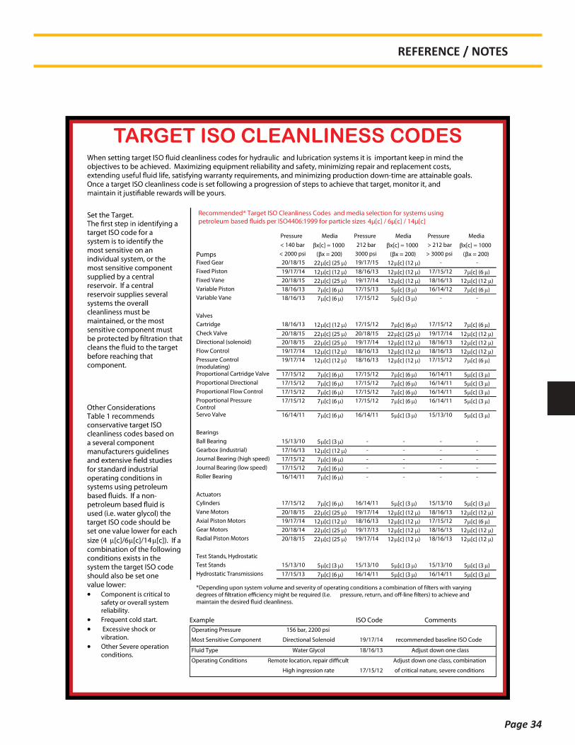
TARGET ISO CLEANLINESS CODES
Í»¬ ¬¸» Ì¿®¹»¬ò
¬¿®¹»¬ ×ÍÑ ½±¼» º±® ¿ §¬»³ · ¬± ·¼»²¬·º§ ¬¸» ³±¬ »²·¬·ª» ±² ¿² ·²¼·ª·¼«¿´ §¬»³ô ±® ¬¸» ³±¬ »²·¬·ª» ½±³°±²»²¬ «°°´·»¼ ¾§ ¿ ½»²¬®¿´ ®»»®ª±·®ò ׺ ¿ ½»²¬®¿´ ®»»®ª±·® «°°´·» »ª»®¿´ §¬»³ ¬¸» ±ª»®¿´´ ½´»¿²´·²» ³«¬ ¾» ³¿·²¬¿·²»¼ô ±® ¬¸» ³±¬ »²·¬·ª» ½±³°±²»²¬ ³«¬
¾»º±®» ®»¿½¸·²¹ ¬¸¿¬ ½±³°±²»²¬ò
±¾¶»½¬·ª» ¬± ¾» ¿½¸·»ª»¼ò Ó¿¨·³·¦·²¹ »¯«·°³»²¬ ®»´·¿¾·´·¬§ ¿²¼ ¿º»¬§ô ³·²·³·¦·²¹ ®»°¿·® ¿²¼ ®»°´¿½»³»²¬ ½±¬ô ´·º»ô ¿¬·º§·²¹ ©¿®®¿²¬§ ®»¯«·®»³»²¬ô ¿²¼ ³·²·³·¦·²¹ °®±¼«½¬·±² ¼±©²ó¬·³» ¿®» ¿¬¬¿·²¿¾´» ¹±¿´ò
Ѳ½» ¿ ¬¿®¹»¬ ×ÍÑ ½´»¿²´·²» ½±¼» · »¬ º±´´±©·²¹ ¿ °®±¹®»·±² ±º ¬»° ¬± ¿½¸·»ª» ¬¸¿¬ ¬¿®¹»¬ô ³±²·¬±® ·¬ô ¿²¼
Ю»«®» Ó»¼·¿ Ю»«®» Ó»¼·¿ Ю»«®» Ó»¼·¿
ä ïì𠾿® ¨Å½Ã ã ïððð îïî ¾¿® ¨Å½Ã ã ïððð â îïî ¾¿® ¨Å½Ã ã ïððð
Ы³° ä îððð °· ø ¨ ã îðð÷ íððð °· ø ¨ ã îðð÷ â íððð °· ø ¨ ã îðð÷
Ú·¨»¼ Ù»¿® îðñïèñïë îî Žà øîë ÷ ïçñïéñïë ïî Žà øïî ÷ ó ó
Ú·¨»¼ 笱² ïçñïéñïì ïî Žà øïî ÷ ïèñïêñïí ïî Žà øïî ÷ ïéñïëñïî é Žà øê ÷
Ú·¨»¼ Ê¿²» îðñïèñïë îî Žà øîë ÷ ïçñïéñïì ïî Žà øïî ÷ ïèñïêñïí ïî Žà øïî ÷
Ê¿®·¿¾´» 笱² ïèñïêñïí é Žà øê ÷ ïéñïëñïí ë Žà øí ÷ ïêñïìñïî é Žà øê ÷
Ê¿®·¿¾´» Ê¿²» ïèñïêñïí é Žà øê ÷ ïéñïëñïî ë Žà øí ÷ ó ó
Ê¿´ª»
Ý¿®¬®·¼¹» ïèñïêñïí ïî Žà øïî ÷ ïéñïëñïî é Žà øê ÷ ïéñïëñïî é Žà øê ÷
ݸ»½µ Ê¿´ª» îðñïèñïë îî Žà øîë ÷ îðñïèñïë îî Žà øîë ÷ ïçñïéñïì ïî Žà øïî ÷
Ü·®»½¬·±²¿´ ø±´»²±·¼÷ îðñïèñïë îî Žà øîë ÷ ïçñïéñïì ïî Žà øïî ÷ ïèñïêñïí ïî Žà øïî ÷
Ú´±© ݱ²¬®±´ ïçñïéñïì ïî Žà øïî ÷ ïèñïêñïí ïî Žà øïî ÷ ïèñïêñïí ïî Žà øïî ÷
Ю»«®» ݱ²¬®±´ ø³±¼«´¿¬·²¹÷
ïçñïéñïì ïî Žà øïî ÷ ïèñïêñïí ïî Žà øïî ÷ ïéñïëñïî é Žà øê ÷
Ю±°±®¬·±²¿´ Ý¿®¬®·¼¹» Ê¿´ª» ïéñïëñïî é Žà øê ÷ ïéñïëñïî é Žà øê ÷ ïêñïìñïï ë Žà øí ÷
Ю±°±®¬·±²¿´ Ü·®»½¬·±²¿´ ïéñïëñïî é Žà øê ÷ ïéñïëñïî é Žà øê ÷ ïêñïìñïï ë Žà øí ÷
Ю±°±®¬·±²¿´ Ú´±© ݱ²¬®±´ ïéñïëñïî é Žà øê ÷ ïéñïëñïî é Žà øê ÷ ïêñïìñïï ë Žà øí ÷
Ю±°±®¬·±²¿´ Ю»«®» ݱ²¬®±´
ïéñïëñïî é Žà øê ÷ ïéñïëñïî é Žà øê ÷ ïêñïìñïï ë Žà øí ÷
Í»®ª± Ê¿´ª» ïêñïìñïï é Žà øê ÷ ïêñïìñïï ë Žà øí ÷ ïëñïíñïð ë Žà øí ÷
Þ»¿®·²¹
Þ¿´´ Þ»¿®·²¹ ïëñïíñïð ë Žà øí ÷ ó ó ó ó
Ù»¿®¾±¨ ø·²¼«¬®·¿´÷ ïéñïêñïí ïî Žà øïî ÷ ó ó ó ó
Ö±«®²¿´ Þ»¿®·²¹ ø¸·¹¸ °»»¼÷ ïéñïëñïî é Žà øê ÷ ó ó ó ó
Ö±«®²¿´ Þ»¿®·²¹ ø´±© °»»¼÷ ïéñïëñïî é Žà øê ÷ ó ó ó ó
α´´»® Þ»¿®·²¹ ïêñïìñïï é Žà øê ÷ ó ó ó ó
ß½¬«¿¬±®
ݧ´·²¼»® ïéñïëñïî é Žà øê ÷ ïêñïìñïï ë Žà øí ÷ ïëñïíñïð ë Žà øí ÷
Ê¿²» Ó±¬±® îðñïèñïë îî Žà øîë ÷ ïçñïéñïì ïî Žà øïî ÷ ïèñïêñïí ïî Žà øïî ÷
ߨ·¿´ 笱² Ó±¬±® ïçñïéñïì ïî Žà øïî ÷ ïèñïêñïí ïî Žà øïî ÷ ïéñïëñïî é Žà øê ÷
Ù»¿® Ó±¬±® îðñïèñïì îî Žà øîë ÷ ïçñïéñïí ïî Žà øïî ÷ ïèñïêñïí ïî Žà øïî ÷
ο¼·¿´ 笱² Ó±¬±® îðñïèñïë îî Žà øîë ÷ ïçñïéñïì ïî Žà øïî ÷ ïèñïêñïí ïî Žà øïî ÷
Ì»¬ ͬ¿²¼ô ا¼®±¬¿¬·½
Ì»¬ ͬ¿²¼ ïëñïíñïð ë Žà øí ÷ ïëñïíñïð ë Žà øí ÷ ïëñïíñïð ë Žà øí ÷
ا¼®±¬¿¬·½ Ì®¿²³··±² ïéñïëñïí é Žà øê ÷ ïêñïìñïï ë Žà øí ÷ ïêñïìñïï ë Žà øí ÷
λ½±³³»²¼»¼ö Ì¿®¹»¬ ×ÍÑ Ý´»¿²´·²» ݱ¼» ¿²¼ ³»¼·¿ »´»½¬·±² º±® §¬»³ «·²¹
ìkŽà ñ êkŽà ñ ïìkŽÃ
Ѭ¸»® ݱ²·¼»®¿¬·±² Ì¿¾´» ï ®»½±³³»²¼ ½±²»®ª¿¬·ª» ¬¿®¹»¬ ×ÍÑ ½´»¿²´·²» ½±¼» ¾¿»¼ ±² ¿ »ª»®¿´ ½±³°±²»²¬ ³¿²«º¿½¬«®»® ¹«·¼»´·²»
º±® ¬¿²¼¿®¼ ·²¼«¬®·¿´ ±°»®¿¬·²¹ ½±²¼·¬·±² ·² §¬»³ «·²¹ °»¬®±´»«³
«»¼ ø·ò»ò ©¿¬»® ¹´§½±´÷ ¬¸» ¬¿®¹»¬ ×ÍÑ ½±¼» ¸±«´¼ ¾» »¬ ±²» ª¿´«» ´±©»® º±® »¿½¸
·¦» øì ŽÃñê ŽÃñïì ŽÃ÷ò ׺ ¿ ½±³¾·²¿¬·±² ±º ¬¸» º±´´±©·²¹ ½±²¼·¬·±² »¨·¬ ·² ¬¸» §¬»³ ¬¸» ¬¿®¹»¬ ×ÍÑ ½±¼» ¸±«´¼ ¿´± ¾» »¬ ±²» ª¿´«» ´±©»®æ
ݱ³°±²»²¬ · ½®·¬·½¿´ ¬±
¿º»¬§ ±® ±ª»®¿´´ §¬»³ ®»´·¿¾·´·¬§ò
Ú®»¯«»²¬ ½±´¼ ¬¿®¬ò
Û¨½»·ª» ¸±½µ ±®
ª·¾®¿¬·±²ò
Ѭ¸»® Í»ª»®» ±°»®¿¬·±²
½±²¼·¬·±²ò
Û¨¿³°´» ×ÍÑ Ý±¼» ݱ³³»²¬
Ñ°»®¿¬·²¹ Ю»«®» ïëê ¾¿®ô îîðð °·
Ó±¬ Í»²·¬·ª» ݱ³°±²»²¬ Ü·®»½¬·±²¿´ ͱ´»²±·¼ ïçñïéñïì ®»½±³³»²¼»¼ ¾¿»´·²» ×ÍÑ Ý±¼»
Ú´«·¼ ̧°» É¿¬»® Ù´§½±´ ïèñïêñïí ß¼¶«¬ ¼±©² ±²» ½´¿
Ñ°»®¿¬·²¹ ݱ²¼·¬·±² ß¼¶«¬ ¼±©² ±²» ½´¿ô ½±³¾·²¿¬·±²
Ø·¹¸ ·²¹®»·±² ®¿¬» ïéñïëñïî ±º ½®·¬·½¿´ ²¿¬«®»ô »ª»®» ½±²¼·¬·±²
½´·½µ ¸»®» ¬± ®»¬«®² ¬± ©»¾·¬»
REFERENCE / NOTES
Page 35
REFERENCE / NOTES
(in.)
(sq
. in
.)(l
bs
)(f
t-lb
s)
(ft-
lbs)
(ft-
lbs)
(sq
. in
.)(l
bs)
(ft-
lbs)
(ft-
lbs)
(ft-
lbs)
1/4
20
0.0
31
83
341
10
11
14
28
0.0
36
43
81
912
13
16
5/1
61
80
.05
24
55
05
22
23
29
24
0.0
58
16
09
724
25
32
3/8
16
0.0
77
58
136
38
41
51
24
0.0
87
89
22
243
46
58
7/1
61
40
.10
63
11
16
26
16
58
12
00.1
18
712
46
568
73
91
1/2
13
0.1
41
91
489
99
39
912
42
00.1
60
016
79
510
51
12
14
0
5/8
11
0.2
26
02
288
31
79
19
123
81
80.2
56
025
91
620
22
16
27
0
3/4
10
0.3
34
53
386
43
17
33
942
31
60.3
73
037
76
235
43
78
47
2
7/8
90
.46
17
46
75
15
11
54
568
21
40.5
09
551
58
456
46
02
75
2
18
0.6
05
76
133
27
67
81
810
22
14
0.6
79
968
83
986
09
18
11
47
1
1/8
70
.76
33
77
28
21
08
71
15
914
49
1
1/4
70
.96
91
98
12
31
53
31
63
520
44
12
1.0
72
910
86
36
169
71
811
22
63
1
3/8
61
.15
49
11
693
22
01
02
14
426
80
12
1.3
14
713
31
15
228
82
440
30
51
1
1/2
61
.40
53
14
228
22
66
82
84
635
57
12
1.5
81
016
00
79
300
13
202
40
02
1
3/4
51
.89
95
19
232
04
20
74
48
756
09
24
.52
.49
82
25
294
56
32
46
74
584
32
K =
0.2
0K
= 0
.15
K =
0.1
6K
= 0
.20
thre
ad
s
pe
r in
ch
Te
nsile
Str
ess
Are
a
Cla
mp
Lo
ad
Un
ifie
d C
oa
rse
Th
read
Se
rie
sF
ine
Th
rea
d S
eri
es
No
min
al
Dia
thre
ads
pe
r in
ch
Te
nsile
Str
ess
Are
a
Cla
mp
Lo
ad
Tig
hte
nin
g T
orq
ue
Tig
hte
nin
g T
orq
ue
K =
0.1
5K
= 0
.16
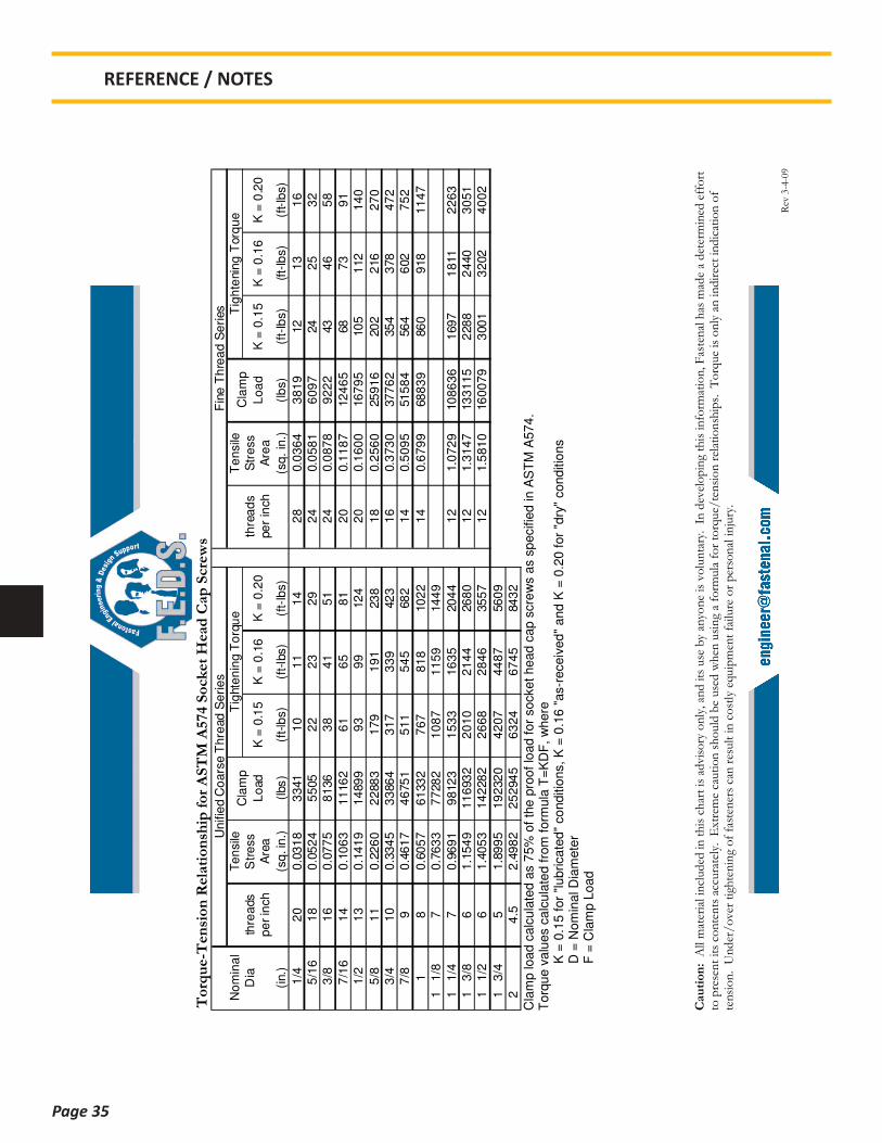
C
lam
p loa
d c
alc
ula
ted a
s 7
5%
of
the p
roof
load f
or
socket head c
ap s
cre
ws a
s s
pecifie
d in A
ST
M A
574
. T
orq
ue v
alu
es c
alc
ula
ted f
rom
form
ula
T=
KD
F,
where
K =
0.1
5 f
or
"lubrica
ted
" co
nditio
ns, K
= 0
.16 "
as-r
eceiv
ed
" a
nd K
= 0
.20 f
or
"dry
" conditio
ns
D
= N
om
inal D
iam
ete
r
F =
Cla
mp L
oad

Page 36
REFERENCE / NOTES

Page 37
REFERENCE / NOTES

Page Left Intentionally Blank

All information given in this Manual is current and valid per the information available at the time of publication. (Please check the updated revision date at the bottom of each page.)
American Piledriving Equipment (APE) reserves the right to implement changes without prior notice.
Please visit www.apevibro.com for the most recent version of this publication.
AMERICAN PILEDRIVING EQUIPMENT, INC.7032 S. 196th StreetKent, Washington 98032Office: 253-872-0141Toll Free: 800-248-8498Fax: 253-872-8710


