62
IVQ in Electrical and Electronic Engineering 8030 (2000) Technician Diploma www.cityandguilds.com
| Date post: | 24-Oct-2014 |
| Category: |
Documents |
| Upload: | bright-francis-anthonio |
| View: | 278 times |
| Download: | 7 times |

IVQ in Electrical andElectronic Engineering8030 (2000)Technician Diploma
www.cityandguilds.com

Publications and enquiriesCity & Guilds publications are available from
Publications SalesCity & Guilds1 Giltspur StreetLondonEC1A 9DDUnited KingdomT +44 (0)20 7294 2850F +44 (0)20 7294 3387
General information about City & Guilds may be obtained from Customer Relations at the above address, or on 020 7294 3500, or by [email protected]
Equal opportunitiesCity & Guilds fully supports the principle of equal opportunities and we are committed to satisfying this principle in all our activities and published material.
Every effort has been made to ensure that the information contained in this publication is true and correct at the time of going to press. However, City & Guilds’ products and services are subject to continuous development and improvement and the right is reserved to change products and services from time to time. City & Guilds cannot accept liability for loss or damage arising from the use of information in this publication.
©2003 The City and Guilds of London Institute. All rights reserved.City & Guilds is a trademark of the City and Guilds of London Institute.
1 Giltspur StreetLondonEC1A 9DDT +44 (0)20 7294 2468F +44 (0)20 7294 2400www.cityandguilds.com

IVQ in Electrical andElectronic Engineering8030 (2000)Technician Diploma
ST80275/06.03/I-00036357
CopyrightThis document is copyrighted by City & Guilds (except where the copyright is acknowledged to be held by another party). Permission is given, however, for registered testing centres to reproduce pages for their own use.

[ This page is intentionally blank ]

05 IVQ in Electrical and Electronic Engineeering 8030 (2000)
05 About City & Guilds
05 Introduction to this programme
05 Certificate
05 Diploma
05 Advanced Diploma
05 Full Technological Diploma
05 Making entries for assessments
05 Resources
06 Summary of assessment
06 Diplomas
06 Award number
06 Component numbers
06 Assessments
06 Technician Diploma in Applied Electrical Engineering
06 Technician Diploma in Electrical Engineering Theory
07 Technician Diploma in Applied Electronic Engineering
07 Technician Diploma in Electronic Engineering Theory
07 Fixed and free-date assessments
07 Results and certification
08 How to offer this programme
08 Subject approval
08 Examination centre approval
08 Other information
08 Designing courses of study
08 Presentation format of units
08 Competence statements
08 Practical assignments
09 Entry levels
09 Progression routes and recognition
09 Useful publications
11 SyllabusIVQ in Electrical and Electronic Engineering 8030 (2000)
12 210 Engineering Fundamentals 2
18 211 Computer Aided Communication Practical Assignments
27 212 Electronics
31 213 Electronics Practical Assignments
41 214 Electrical Power
45 215 Electrical Practical Assignments
53 Appendix APractical assignments
53 Practical assignments
53 Instructor notes
53 Candidate instructions
53 Marking
53 Supervision
53 Records, results and certification
53 Visiting verifier
54 Model of candidate assessment record forms
57 Appendix BThe levels of our awards
57 Progressive structure
Contents

[ This page is intentionally blank ]

About City & Guilds
We provide assessment and certification services for schools andcolleges, business and industry, trade associations andgovernment agencies in more than 100 countries. We have over120 years of experience in identifying training needs, developingassessment materials, carrying out assessments and trainingassessment staff. We award certificates to people who haveshown they have mastered skills that are based on world-classstandards set by industry. City & Guilds International provides aparticular service to customers around the world who needhigh-quality assessments and certification.
Introduction to this programme
We have designed the Technician Diplomas in Electrical andElectronic Engineering programme for those undergoing trainingor employed in this area of work. The programme aims to reflectthe international nature of the knowledge, skills and activitiesneeded for different countries or cultures.
We provide certificates for all work-related areas at seven levelswithin our structure of awards shown in appendix B. Thisprogramme covers level 3. The standards and assessments forthe certificate (level 2) and the advanced diploma (level 4) arepublished separately.
CertificateThe certificate (about 300 guided learning hours) provides abroad introduction to the theory and practical sides ofengineering for a front-line worker or a person beginning anacademic training programme.
DiplomaThe diploma (about 600 guided learning hours) provides morepractice involving a broader range of skills appropriate to aperson who may also supervise, or who is going on into highereducation.
Advanced diplomaThe advanced diploma (about 600 guided learning hours) takesthese skills to the level appropriate for a person preparing for orworking in first level management. It is also appropriate forsomeone who wants to receive specialised training at a high level.
We stress that these figures are only a guideline and that we awardcertificates and diplomas for gaining and showing skills bywhatever mode of study, and not for periods of time spent in study.
Full technological diplomaWe will award the Full Technological Diploma (FTD) in Electricaland Electronic Engineering to someone who is at least 21, whohas had at least two years relevant industrial experience, and whohas successfully finished the assessments for the diploma andadvanced diploma levels of this award. If candidates enter for thisdiploma, they must also send us a portfolio of evidence tosupport their application.
Making entries for assessments
Candidates can only be entered for the assessments in thissubject if the approved examination centres agree. Candidatesmust enter through an examination centre we have approved tocarry out the assessments for 8030 awards.
There are two ways of entering candidates for assessments.
Internal candidatesCandidates can enter for examinations if they are taking or havealready finished a course at a school, college or similar traininginstitution that has directed their preparation whether by going toa training centre, working with another institution, or by openlearning methods.
External candidatesThese are candidates who have not finished a programme asdescribed above. The examination centres must receive theirapplication for entry well before the date of the examinationconcerned. This allows them to act on any advice you give aboutassessment arrangements or any further preparation needed.External candidates carrying out practical assignments andprojects, will need extra time and guidance to make sure that theymeet all the requirements for this part of the assessment.
In this publication we use the term ‘centre’ to mean a school,college, place of work or other institution.
Resources
If you want to use this programme as the basis for a course, youmust read this booklet and make sure that you have the staff andequipment to carry out all parts of the programme. If there are nofacilities for realistic practical work, we strongly recommend thatyou develop links with local industry to provide opportunities forhands-on experience.
IVQ in Electrical and Electronic Engineeering 8030 (2000)
Regulations: 2000 edition 05

Summary of Assessment
There is one level of this award.
Diplomas
We use a numbering system to allow entries to be made for ourawards. The numbers used for this programme are as follows.
Award number8030-22 Technician Diploma in
Applied Electrical Engineering
Technician Diploma inElectrical Engineering Theory
Technician Diploma inApplied Electronic Engineering
Technician Diploma inElectronic Engineering Theory
We use award numbers to describe the subject and level of the award.
Component numbers210 Engineering Fundamentals 2211 Computer Aided Communication Practical Assignments212 Electronics213 Electronic Practical Assignments214 Electrical Power215 Electrical Practical Assignments
We use component numbers to show units for which we mayaward a Certificate of Unit Credit.
We use these numbers throughout this booklet. You must usethese numbers correctly if you send forms to us.
Assessments
Technician Diploma in Applied Electrical EngineeringTo carry out what is needed for the Technician Diploma in AppliedElectrical Engineering candidates must be successful in all of thefollowing assessments.
8030-22-210 Engineering Fundamentals 2 (written paperwhich lasts three hours)
[8030-22-211] Computer-Aided Communication PracticalAssignments
8030-22-214 Electrical Power (written paper which lasts threehours)
[8030-22-215] Electrical Practical Assignments(Total two written papers)
The practical assignments are carried out during the learningprogramme and should be finished by the date of the writtenexamination so you can send all the results to us. (See appendicesA and B.)
To receive this award candidates must carry out the followingpractical assignments.
• 211/1, 211/2, 211/3, 215/1, 215/2 and 215/3(Total six practical assignments)
Technician Diploma in Electrical Engineering TheoryTo carry out what is needed for the Technician Diploma inElectrical Engineering Theory, candidates must be successful in allof the following assessments.
8030-22-210 Engineering Fundamentals 2 (written paperwhich lasts three hours)
8030-22-214 Electrical Power (written paper which lasts three hours)
(Total two written papers)
There are no practical assignments for this award.
IVQ in Technician Awards in Electrical and Electronic Engineering 8030 (2000)06

Technician Diploma in Applied Electronic EngineeringTo carry out what is needed for the Technician Diploma in AppliedElectronic Engineering candidates must be successful in all of thefollowing assessments.
8030-22-210 Engineering Fundamentals 2 (written paperwhich lasts three hours)
[8030-22-211] Computer-Aided Communication PracticalAssignments
8030-22-212 Electronics (written paper which lasts three hours)
[8030-22-213] Electronic Practical Assignments(Total two written papers)
The practical assignments are carried out during the learningprogramme and should be finished by the date of the writtenexamination so you can send all the results to us. (See appendicesA and B.)
To receive this award candidates must complete the followingpractical assignments.
• 211/1, 211/2, 211/3, 213/1, 213/2 and 213/3(Total six practical assignments)
Technician Diploma in Electronic Engineering TheoryTo carry out what is needed for the Technician Diploma inElectronic Engineering Theory candidates must be successful inall of the following assessments.
8030-22-210 Engineering Fundamentals 2 (written paperwhich lasts three hours)
8030-22-212 Electronics (written paper which lasts three hours)
(Total two written papers)
There are no practical assignments for this award.
Fixed and free dates assignments
We provide assessments in two ways.
a Fixed dateThese are assessments which are carried out on dates andtimes we set. These assessments have no brackets around their numbers.
b Free dateThese are assessments which are carried out at a college orother training establishment on a date or over a period whichthe college chooses. These assessments have brackets aroundtheir numbers.
In this programme the written assessments are fixed date. Thepractical assignments and the project are free date.
You must carry out assessments according to our InternationalDirectory of Examinations and Assessments. If there are anydifferences between information in this publication and the currentdirectory, the Directory has the most up-to-date information.
Results and certification
Everyone who enters for our certificates, diplomas, and advanceddiplomas receives a ‘Notification of Candidate Results’ givingdetails of how they performed.
If candidates successfully finish any assessment within thisprogramme (for example, any one of the examination papers)they will receive a Certificate of Unit Credit towards the certificateor diploma for which they are aiming. We grade courseworkassessments (practical assignments) as pass or fail. We gradewritten assessments on the basis of fail, pass, credit ordistinction. The Certificate of Unit Credit will not mentionassessments which they do not enter, which they failed or fromwhich they were absent.
Each certificate or diploma clearly states what candidates need forfull certification at the relevant level, allowing schools, colleges andemployers to see whether they have met the full requirements.
If candidates successfully finish all the requirements for a fullcertificate or a diploma, they will automatically receive theappropriate certificate.
We will send the ‘Notification of Candidate Results’, Certificates ofUnit Credit, certificates, diplomas and advanced diplomas to theexamination centre to be awarded to successful candidates. It isyour responsibility to give the candidates the certificates. Ifcandidates have a question about the results and certificates,they must contact you. You may then contact us if necessary.
We will also send you a results list showing how all candidates performed.
Regulations: 2000 edition 07

How to offer this programme
To offer this programme you must get approval from us. There aretwo categories of approval.
Subject approvalWe give approval to offer a teaching course based on this syllabus.
Examination centre approvalWe give approval to enter candidates for examinations.
To be approved by us to offer a teaching course you must send usthe application form.
To enter candidates for examinations you must be approved by usas an examination centre. For this programme it is possible to actas a registered examination centre only, and accept externalcandidates. Approved examination centres must provide suitablefacilities for taking examinations, secure places to keep theexamination papers and materials, and may have an appointedvisiting verifier to review practical work.
After we have received and accepted an application, we will sendan approval letter confirming this. You can then send entries in atany time using the International Directory of Examinations andAssessments for guidance.
Please note that in this section we have provided anoverview of centre approval procedures. Please refer tothe current issue of ‘Delivering International Qualifications– Centre Guide’ for full details of each aspect of theseprocedures.
Other informationDesigning courses of studyCandidates for the various Technician Diplomas in Electrical andElectronic engineering will have come from different backgroundsand will have different employment and training experiences. Werecommend the following:
• carry out an assessment of the candidates’ achievements soyou can see what learning they already have and decide thelevel of entry they will need; and
• consider what learning methods and places will best suit them.
When you assess a candidate’s needs, you should designteaching programmes that consider:
• what, if any, previous education qualifications or training thecandidate has, especially in the various general vocationaleducation certificates we provide; and
• what, if any, previous practical experience the candidate haswhich is relevant to the aims of the programme and from whichthey may have learned the relevant skills and knowledge.
When you choose learning methods and places, you shouldconsider the results of your assessments and whether thefollowing are available.
• Open or distance learning material.• Workplace learning that can be carried out on site or between
you and a local workplace. This will allow the candidates accessto specialised equipment and work experience.
• Working with other registered centres to share facilities.• Opportunities for co-operative learning between candidates for
different certificates who need to gain similar skills.
As long as the candidates meet the aims of this learningprogramme the structures of courses of study are up to you. So, itis possible to include extra topics that meet local needs.
You should avoid teaching theory alone. As far as possible thepractical work should be closely related to work in the classroomso that candidates use their theory in a realistic workenvironment. You can use formal lectures in the classroom withappropriate exercises and demonstrations. Candidates shouldkeep records of the practical work they do so they can refer to it ata later date.
We assume that you will include core skills, such as numeracy,communication, working with people, and organisation andplanning throughout a teaching programme.
Presentation format of unitsCompetence statementsMost units start with a section on practical competences whichshows the practical skills candidates must have.
For example:
‘211.20 Present data in graphical format.Graphical format: bar chart, pie chart, histogram,frequency polygon’
In the above statement ‘Graphical format’ is given as a rangewhich the candidate should be familiar with. Candidates shouldcover the complete range. When a range starts with theabbreviation ‘eg’ the candidates only need to cover some of theranged areas or you can use suitable alternatives.
Competence statements cover practical skills and knowledgerequirements. The knowledge needed is closely linked to thepractical competences, so it is best to teach the two together sothat the candidate understands the topic more.
Practical assignmentsYou should make sure all practical assignments are supervisedand instructors should make sure that the results reflect thecandidate’s own work. You must hold all the documents andmaterial in a file (portfolio) for each candidate for eight weeksafter the application for a certificate. You must also keep separaterecords of the dates of all attempts by each candidate.
IVQ in Technician Awards in Electrical and Electronic Engineering 8030 (2000)08

Entry levels
We consider the following programmes to be relevant preparation for this programme.
Technician Certificate in Electrical and Electronic Engineering (8030)
We also consider the following Pitman Qualifications award as relevant alongside this programme.
English for Speakers of Other Languages – higher intermediate level
If candidates do not have the above qualifications, they shouldhave secondary school leaving passes in English, mathematicsand science.
Progression routes and recognition
We consider the following programmes to be relevantprogression routes from this programme.
Advanced Technician Diploma in Electrical and ElectronicEngineering 8030 (2000)
A number of UK universities and other higher education institutionswill accept success at diploma or advanced diploma level of thisprogramme for direct entry onto higher-level programmes. Thedecision to accept a candidate on to a degree programme, and thelevel of entry, is up to the institution. We provide details oforganisations recognising achievement in this programme.
Useful publications
We can provide a list of suggested text books covering specificareas of this programme. We may also have knowledge aboutother support materials. You should make sure that you have thelatest information. We will automatically send updated lists tocentres we have approved to offer this programme.
Plain English Campaign’s Crystal Mark only covers the Technician Awards in Engineering regulations.
Regulations: 2000 edition 09

[ This page is intentionally blank ]

Component numbers and titles
210 Engineering Fundamentals 2
211 Computer Aided Communication
212 Electronics
213 Electronic Practical Assignments
214 Electrical Power
215 Electrical Practical Assignments
SyllabusIVQ in Electrical and Electronic Engineering 8030 (2000)
Syllabus: 2000 edition 11

Introduction
The aim of this unit is to further develop the concepts and skillsacquired at Certificate level. It also supports a range of units at theDiploma level and serves as a pre-requisite for further studies.
Mathematics
Knowledge requirements
Instructors must ensure that candidates are able to:
Statistics210.1 Collect data from practical work in other subjects and
from publications.
210.2 Distinguish between discrete and continuous data.
210.3 Distinguish between a sample and a population.
210.4 Determine the range and approximate density of thedata and use this information to form appropriategroups (equal and unequal) to cover the set of data.
210.5 Define frequency and relative frequency.
210.6 Determine, using a tally count, the frequency and hencethe relative frequency of objects in each group.
210.7 Identify the data using either the frequencies or relativefrequencies by suitable fully labelled diagrams.Diagrams: bar charts, component bar charts, pie charts, pictograms
210.8 Use a labelled histogram and frequency polygon torepresent a given set of data.
210.9 Calculate cumulative frequencies and draw an ogive.
210.10 Interpret descriptive data summarised in tablesand in diagrams.
210.11 Describe the need to measure the dispersion of data.
210.12 Define standard deviation and variance.
210.13 Calculate values of standard deviation for both groupedand ungrouped data.
Logarithms210.14 Define x as lg N when N = 10x
210.15 Define x as ln N when N = ex
210.16 Define the inverse of ax = y as x = logay
210.17 Apply change of base rule where loga x =
210.18 State and apply the laws of logarithms in the followingforms where b is any baseForms:
logbMN = logbM + logbN, logbM/N = logbM – logbN,logbNa = a logbN
Algebra210.19 Simplify and evaluate algebraic expressions involving
negative indices.
210.20 Evaluate algebraic expressions involving fractional indices expressed in both numerator/denominator and decimal form.
210.21 Transpose formulae which contain a root or power.
210.22 Transpose formulae in which the subject appears inmore than one term.
210.23 Simplify and evaluate algebraic expressions involvingwhole number indices.
210.24 Simplify and evaluate algebraic expressions involvingnegative number indices.
210.25 Solve linear equations. Solve a pair of simultaneous linear equations in two unknowns by both substitution and elimination.
210.26 Factorize quadratic expressions of the form of ax2 = bx +c and solve quadratic equations by factorisation and formula.
Geometry and trigonometry210.27 Express angular rotations in multiples of radians. One
rotation is 2π radians, n rotations is 2πn radians
210.28 Use the relationship s = r to determine the length of arc of a circle.
210.29 Use the relationship A = 1⁄2r2 to determine the area of asector of a circle.
210.30 Solve problems involving areas and angles measuredin radians.
210.31 Define trigonometric functions of an acute angle.Trigonometric functions: sine, cosine, tangent
210.32 Obtain values for the three trigonometric functions for angles of any magnitude from tables and from a calculator.
210.33 Determine an acute angle given a trigonometric functionvalue. Angle obtained from sin -1 ; cos -1 ; tan -1
210.34 State the relationships: cos = sin (90˚ – ) and sin = cos (90˚ – ) for values of from 0 to 90˚
logbx
logba
210 Engineering Fundamentals 2
IVQ in Technician Awards in Electrical and Electronic Engineering 8030 (2000)12

210.35 Solve problems by using trigonometric function valuesand/or Pythagoras’ theorem.
210.36 Apply the sine and cosine rules to the solution of anytriangle given sufficient information.Sine Rule: a/sin A = b/sin B = c/sin CCosine Rule: a2 = b2 +c2 -2bc cos AInformation: one side and any 2 angles, two sides andan angle opposite to one of the given sides, two sidesand the angle between them, three sides
Graphs210.37 Solve graphically a pair of simultaneous equations
in two unknowns.Linear equations:
y = m1x+cy = m2x+c2
210.38 Sketch graphs of parabolas relating to quadratics.Parabolas:
y = ax2
y = ax2 + cy = (x + b)2
y = (x + b)2 + cy = ax2 + bx + c
210.39 Approximate the gradient of a non-linear graph bydefining the slope of a secant line between two points on the curve.
210.40 Understand the accuracy of the above approximationimproves when the two points are brought closertogether.
210.41 Approximate areas under non-linear graphs and the x-axis by splitting the region into uniform trapeziums. Non-linear graphs: parabolas, cubics,logarithmic, sinusoidal
210.42 Understand the accuracy of the above approximationimproves as the number of trapeziums within thedefined region is increased.
210.43 Recognise the characteristic graphical and algebraicform of linear functions, eg y = mx + c
210.44 Sketch graphs of linear functions and identify slopes andintercepts and determine the corresponding linear laws.
210.45 Identify polynomial functions of order 2 or more resultsin a non-linear graph.
210.46 Sketch graphs of simple quadratic functions, identify theintercept and where appropriate the roots.
210.47 Identify that an odd-degree polynomial possesses atleast one real root.
210.48 Sketch graphs of simple trigonometric functions and identify their periodic nature.Functions: sine, cosine, tangent
210.49 Sketch graphs of simple exponential and logarithmic functions.
Calculus210.50 Determine average and instantaneous gradients of
graphs of simple functions.Simple functions:
y = mx + cy = ax2
y = ekx
y = sin x
210.51 Deduce the chord of a graph reduces to the tangents ata point as the arc reduces to zero.
210.52 Identify x and y as incremental changes between twopoints on graph.
210.53 Define as the limiting value of the ratio when
dx 0 and hence as the gradient of a graph at a particular point.
210.54 Determine the instantaneous gradient of simplefunctions using standard rules.Standard rules:
(xn) = nxn-1, (sin x) = cos x, (ekx) = kekx
210.55 Define integration as inverse of differentiation.
210.56 State the importance of a constant of integration.
210.57 Determine the indefinite integrals ∫ y dx for y = axn, y = sin x, y = ekx.
210.58 Define ∫ab y dx as the area under the graph between
ordinates x = a and x = b.
210.59 Determine the areas under graphs of simple functions.
ddx
ddx
ddx
yx
dydx
Syllabus: 2000 edition 13

Science
Knowledge requirements
Instructors must ensure that candidates are able to:
Statics210.60 Resolve a force into rectangular components.
210.61 Solve problems involving the triangle of forces theoremand application of the principle of concurrence.
210.62 Define a couple and describe its magnitude as a torque.
210.63 Use the principle of moments to calculate the supportreactions of a loaded simply supported beam.Loading: concentrated, uniformly distributed, combined
Stress and strain210.64 Define stress and its unit N/m2 or Pa
Stress: direct tensile and compression, single shear
210.65 Solve problems involving calculation of values of stress.
210.66 Define direct strain.
210.67 Explain Hook’s law and define Young’s modulus.
210.68 Define and explain the term factor of safety as applied todirect and shear loading.
210.69 Solve problems involving direct stress, strain, Young’smodulus and factors of safety.
210.70 Explain the distinction between single and double shear.
210.71 Solve problems involving shear stress, ultimate shearstrength and factors of safety.Problems: rivetted and pinned joints, flanged shaftcouplings, shearing and punching of flat plates
Kinematics210.72 Explain why speed is a scalar quantity whereas velocity
and acceleration are vector quantities.
210.73 Derive the equations for uniformly accelerated linear motion.Equations:
v = u+at s = (u+v)t
s = ut+ at2
v2 = u2+2as
210.74 Use the equations in 210.73 to solve problems involvingvelocity, acceleration, deceleration and distancetravelled by moving objects, eg vehicle, engineeringcomponent, freely falling body, projectile.
210.75 Define angular velocity, angular acceleration and their units.Units:
rad/s, rad/s2
210.76 Derive the relationships between linear and angular motion.Relationships:
v = .ra = .rs = r.
210.77 Perform calculations involving the relationships in210.76 and = 2.π.N where N is rev/s.
210.78 Obtain equations for uniformly accelerated angularmotion by analogy with linear motion.Equations:
2 = 1+.t
= (1+2)t
= 1t + 1⁄2t2
22 + 2.
210.79 Solve problems involving angular motions using theequations in 210.78.
Dynamics210.80 Explain the laws of dry friction.
210.81 Define the coefficient of friction.
210.82 Solve problems involving the force of friction and thecoefficient of friction.
210.83 Solve problems involving the work done by a constant force.Force: constant, inclined, uniformly varying
210.84 Derive the relationships for potential energy and linearkinetic energy.Relationships:
P.E. = mgh
K.E. = mv212
12
12
12
IVQ in Technician Awards in Electrical and Electronic Engineering 8030 (2000)14

210.85 Derive the relationships for work done (W) and power (P)transmitted by a torque (T).Relationships:
W = T
P = T
210.86 Solve problems involving potential energy, kineticenergy, torque and power.
Simple machines210.87 Explain the function of a machine and the term
simple machine.
210.88 Define the terms velocity ratio (VR), mechanicaladvantage (MA) and efficiency and solve problems on arange of machines.Machines: belt drives, gear trains, pulley blocks,screwjack, worm and wheel, winch
210.89 Describe the effects of friction in machines.Effects: generation of heat, unwanted reduction in efficiency
210.90 Draw graphs of effort (E) against load (W) fromexperimental results on simple machines and obtain thelaw of the machine. E = aW + b. Show that the limitingvalue of efficiency is 1/aVR.
210.91 Explain the term overhauling and why simple liftingmachines are designed to have an efficiency of less than 50%.
Heat210.92 Define thermal conductivity and state that thermal
resistance is the reciprocal of conductance.
210.93 Derive an expression for the heat conducted in terms ofcross sectional area (A), length (l) of the conductor,temperature difference (T2-T1) and the coefficient ofthermal conductivity (k).
Q =
210.94 Solve simple problems related to heat transfer byconduction.
210.95 Explain Boyle’s law and Charles’ law.
210.96 Combine the laws in 210.95 to give the general gas law PV/T = a constant.
210.97 Solve problems relating to pressure, volume andtemperature of gas.
Direct current electrical circuits210.98 Explain Ohm’s law and solve problems relating to
voltage, current and resistance.
210.99 Identify from electrical circuit diagrams, series andparallel connections of resistors and in each case derivean expression for the equivalent resistance.
210.100 Solve problems involving series, parallel, and series-parallel circuits, limited to four resistors, and Ohm’s law.
210.101 Define resistivity () of a conductor and the unit ofresistivity and use the formula R = L/A to calculate theresistance of a conductor having length L and crosssectional area A.
210.102 Define temperature coefficient of resistance and itsunits, and calculate change in resistance due to achange in temperature.
210.103 State the formulae for power in an electrical circuit.Formulae:
P = VIP = I2.R P = V2/R
210.104 Identify the heating effect of an electrical current, Electrical energy = Power x time, and state the units joules (watt-seconds) or the kWh (kilo-watt hour).
210.105 Solve problems relating to 210.103 and 210.104, involvingcalculations of power and energy in electrical circuits.
210.106 Identify the uses of cells and batteries, includingprimary, secondary, lead acid, nickel-iron and cadmium.Uses: primary cells in portable equipment, secondarycells in rechargeable appliances and vehicles
Alternating current theory210.107 Explain the term ‘single phase alternating current’ and
sketch a graph of a periodic wave.
210.108 Define the terms associated with alternating current.Terms: cycle, frequency, period, peak value,instantaneous value, average value and root meansquare (rms) value
210.109 Solve problems involving conversion of voltage andcurrent, peak average and rms values.
210.110 Define resistance, inductive reactance and capacitivereactance in ac circuits.
210.111 Deduce the relationships between ac voltage andcurrent when a constant voltage is applied to purecomponents.Components: resistance, inductance, capacitance
210.112 For each case in 210.111, sketch graphs of current and voltage against time and the corresponding phasor diagrams.
kA(T2-T1)
l
Syllabus: 2000 edition 15

210.113 Draw to scale phasor diagrams representing alternating currents and voltages in a series circuitcontaining capacitance and resistance and inductanceand resistance.
210.114 State that the power factor of the circuits in 210.113 iscos where is the phase angle between the supplycurrent and the voltage.
210.115 State that the true power in an ac circuit is given by VIcos, where cos , is the power factor.
210.116 Solve simple problems involving the calculation of powerin ac circuits.
210.117 Explain the principle of operation of an ideal transformerand use the relationship
= = to solve simple problems.
Electrical machines210.118 State the principle of electromagnetic induction
and explain the operating principles of electric motors and generators.
210.119 Describe a three-phase ac supply and explain how it cangenerate a rotating magnetic field.
210.120 Describe the external characteristics and uses of seriesand shunt-wound dc motors.
210.121 Describe the external characteristics and uses of acinduction and synchronous motors.
210.122 Explain the need for specialised starter equipment andprotection devices for electric motors.
Electrical measurements210.123 Identify and describe the correct use of electrical and
electronic test instruments for measuring electricalresistance, voltage, current, power and frequency.
210.124 Describe the principle of operation of a moving coilinstrument and a repulsion type moving iron instrument.
210.125 State the meaning of resolution and accuracy as used tospecify the performance of electrical test instruments.
210.126 Describe the causes of error which may arise from theuse of electrical and electronic test instruments.Cause of error: electrical loading, limitation ofresolution and accuracy
210.127 Compare the specifications of analogue and digitalinstruments using manufacturers’ data and calculate theaccuracy which may be attributed to a variety ofdifferent electrical measurements.Measurements: voltage, current and resistanceincluding low and high scale values
IsIp
NpNs
EpEs
IVQ in Technician Awards in Electrical and Electronic Engineering 8030 (2000)16
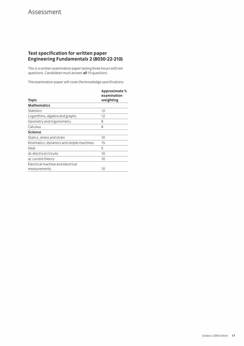
Test specification for written paperEngineering Fundamentals 2 (8030-22-210)
This is a written examination paper lasting three hours with tenquestions. Candidates must answer all 10 questions.
The examination paper will cover the knowledge specifications:
Approximate %examination
Topic weighting
Mathematics
Statistics 12
Logarithms, algebra and graphs 12
Geometry and trigonometry 8
Calculus 8
Science
Statics, stress and strain 10
Kinematics, dynamics and simple machines 15
Heat 5
dc electrical circuits 10
ac current theory 10
Electrical machine and electricalmeasurements 10
Assessment
Syllabus: 2000 edition 17

Introduction
The aim of this unit is to increase candidates’ skills in computertechnology and in particular with databases, spreadsheets andword processing packages.
Practical competences
The candidate must be able to do the following:
Database211.1 Load database software from the operating system or
graphical user interface (GUI).
211.2 Define and create a database structure to store a given setof data.
211.2 Enter data into a database file.
211.3 Save a database file to disk with an appropriate filename ina given location.Location: eg on hard disk, on floppy disk, in sub-directories, in network user area
211.4 Modify a database structure.Modify: add fields, delete fields, change data type,change field length
211.5 Define and execute a single condition search for values on numeric string and date logical fields usingappropriate operators.Operators: less than (<), greater than (>), equal to (=), less than or equal to (<=), greater than or equal to (>=), not equal to (<>), is the same as, is not the same as,contains the string, comes before, comes after
211.6 Use Boolean operators to define and execute multiplecondition searches.Boolean operators: AND, OR
211.7 Define and execute sort criterion for numeric, characterand date fields.
211.8 Print out all or part of a database.All or part: all records in record number order, all recordsas sorted list, records matched by single or multiple searchconditions, one selected record, selected fields only
211.9 Exit database software.
Spreadsheet211.10 Load spreadsheet software from the operating
system or GUI.
211.11 Open a new spreadsheet.
211.12 Create a simple spreadsheet from instructions.
211.13 Set single and global column widths.
211.14 Create and insert appropriate spreadsheet column androw titles.
211.15 Insert and format character and numeric data.Character format: left, centre, right justifiedNumeric format: integer, decimal, scientific, percentage,currency, date
211.16 Insert formulae containing cell addresses and numbers tocarry out calculations.
211.17 Use absolute and relative cell addresses.
211.18 Replicate formulae in a row or column.
211.19 Use the sum and average functions in a spreadsheet.
211.20 Present data in graphical format.Graphical format: bar chart, pie chart, histogram,frequency polygon
211.21 Save a spreadsheet with an appropriate filename.
211.22 Exit spreadsheet software.
Word processing211.23 Load word processing software from the operating
system or GUI.
211.24 Open a new document.
211.25 Layout and enter a simple business letter following aspecified house style.
211.26 Edit the contents of a document.Edit: correct errors, insert word(s), delete word(s), insertparagraph breaks, delete paragraph breaks, move a blockof text, copy a block of text
211.27 Improve the layout of a document.Improve the layout: change justification (left, right, centre,fully justified), indent paragraphs, set tabs, change margins(top, bottom, left, right), change page size/orientation
211.28 Improve the appearance of a document.Improve the appearance: enhance text (bold, italic,underline), change fonts (type, size)
211.29 Spell check a document.
211.30 Save a document with an appropriate filename in a given location.Location: eg floppy disk, hard disk, sub-directory, network user area
211.31 Produce a printed copy of a document on headed paper.
211.32 Exit word processing software.
211 Computer Aided Communication Practical Assignments
IVQ in Technician Awards in Electrical and Electronic Engineering 8030 (2000)18

1 Competence references
211.1 – 211.9
2 Preparation
2.1 Location of the testThe training centre or other venue where supervision andappropriate working conditions will be provided.
2.2 RequirementsA computer system running appropriate databasesoftware and printer connected to the system with paperloaded and set up ready to print.Database software manual.Copy of section 6.
2.3 Instructor notesCandidates are required to produce an engineeringdatabase.
The database structure contains five fields and contains 47 records. The database table thus created will be used toproduce information on particular aspects of the stored data.
3 Candidates’ instructions
3.1 You have 3 hours to produce an engineering databasewhich holds data on an engine driven lawnmower (see section 6).
3.2 Prepare the structure of the database to contain thefollowing fields:
PricePart noNo offDescriptionSection
3.3 Ensure that each field is of suitable length and data type.
3.4 Enter data from section 6 into the database.
3.5 Obtain a print of the database table.
3.6 Sort the file in ascending price order. Print out the sorted file.
3.7 Ask (query) the database to produce and print out thefollowing lists:
3.7.1 all the records which are in the engine section
3.7.2 all the parts costing $1.00 or less
3.7.3 all the records of parts priced between $1.00 and$2.00 inclusive
3.7.4 all the records of which contain a no off value of 3 or 4.
3.8 Ensure your name is on your floppy disk and all your print-outs and hand in to the instructor.
211 Computer Aided CommunicationPractical assignment 211/1: Engineering Database
Syllabus: 2000 edition 19

4 Marking
4.1 Assignment completed in 3 hours. ( )
4.2 Database contains correct number of fields. [ ]
4.3 The structure of the database correctly produced. [ ]
4.4 Data correctly input into the database. [ ]
4.5 The database table printed out. [ ]
4.6 File sorted in ascending order of price. [ ]
4.7 The production of the following lists:
4.7.1 all the records which are in the engine section ( )
4.7.2 all the parts costing $1.00 or less ( )
4.7.3 all the records of parts priced between $1.00 and $2.00 inclusive ( )
4.7.4 all the records of which contain a no off value of 3 or 4. ( )
4.8 Disk and print-outs handed in. [ ]
5 Assignment completion
The candidate will have satisfactorily completed this assignmentif successful in all items marked with a [ ] and at least three ofthe items marked with a ( ).
A period of at least seven days must elapse before anunsuccessful candidate may retake this assignment.
Candidate may retake this assignment or use alternative dataproduced by the instructor.
IVQ in Technician Awards in Electrical and Electronic Engineering 8030 (2000)20

6 Assignment documentation
Manufacturers parts list for a petrol driven lawnmower.
Price Part no No off Description Section
2.20 363 1 Rubber Cable Clip Handlebars
3.20 590 4 Cutterblade Bolt, Nut and Washer Mainframe
0.50 591 2 Washer Mainframe
1.20 1662 1 Key Engine
3.00 2779 4 Cutterblade ‘C’ type Mainframe
6.00 2811 1 Bottom Plate Mainframe
21.50 3607 1 Mainframe Casting Mainframe
5.60 3617 1 Quadrant and Handlebar Bracket Handlebars
2.50 3618 1 Handle Bracket only Handlebars
2.50 3619 2 Upper Bearing Block Handlebars
2.50 3620 2 Lower Bearing Block Mainframe
1.75 3622 1 Spring Handle Handlebars
3.20 3623 1 Rear Flap Handlebars
3.50 3624 1 Handle Grip Handlebars
0.80 3667 2 Rivet Handlebars
2.90 4207 1 Front Axle Plate with Nut N/S Mainframe
2.80 4208 1 Front Axle Plate with Nut O/S Mainframe
4.20 4209 1 Rear Axle Assembly Mainframe
1.60 4210 2 Connecting Rod Engine
2.20 4884 1 Spring Handle Retaining Clip Mainframe
1.20 4912 2 Disc Spring Mainframe
5.50 5704 1 Handlebar Lower Handlebars
1.20 5662 2 Handlebar Clamp Screw Assembly Handlebars
0.90 4918 2 Outer Clamp Plate Handlebars
1.20 5186 1 Banking Plug Mainframe
0.90 5187 2 Axle Plate Setscrew and L/nut Mainframe
8.50 5219 4 8" x 13⁄4" Wheel c/w Bearing Mainframe
4.50 5220 4 Wheel Cover Mainframe
1.00 5221 1 Bearing Mainframe
20.00 9248 1 Engine Engine
3.50 6253 1 Throttle control and blade Engine
1.20 5631 1 Mounting Block Engine
4.50 5649 1 Handlebar Upper Handlebars
3.20 5659 1 Throttle Cable Bracket Engine
2.10 226013 2 Knob Engine
0.80 9070 4 UNF Setscrew 3⁄4" x 5⁄16" Engine
0.80 9080 2 UNF Bolt 11⁄2" x 5⁄16" Mainframe
0.80 9086 4 UNF Bolt 13⁄4" x 5⁄16" Mainframe
1.00 9082 1 UNF Bolt (Full Dog Point) Handlebars
Syllabus: 2000 edition 21

0.90 9116 1 UNF Setscrew 11⁄4" x 3⁄8" Engine
1.10 9209 11 UNF Nylock Nut 5⁄16" Handlebars
1.10 9231 4 UNF Nylon Nut Thin 1⁄2" Engine
0.50 9266 15 O/D Washer 5⁄16" x 5⁄8" Mainframe
0.50 9267 3 Large O/D Washer Engine
0.40 9273 1 S/C Spring Washer Engine
0.90 9303 4 Split Pin 1⁄2" x 3⁄32" Engine
0.90 9358 2 Screw M5 x 30mm Handlebars
IVQ in Technician Awards in Electrical and Electronic Engineering 8030 (2000)22

1 Competence references
211.10-211.22
2 Preparation
2.1 Location of the testThe training centre or other venue where supervision andappropriate working conditions will be provided.
2.2 RequirementsA computer system running appropriate spreadsheetsoftware and printer connected to the system with paperloaded and set up ready to print.
2.3 Instructor notesCandidates are required to produce an engineeringspreadsheet that will calculate the power consumed for anelectrical machine at various phase angles. Theassignment covers data input, equation input, datamanipulation and text and graphical output.
3 Candidates’ instructions
3.1 You must produce an engineering spreadsheet whichcalculates the power consumed for an electrical machineat various phase angles. You have 3 hours to complete this assignment.
3.2 Enter a suitable TITLE, your NAME, COURSE and DATE atthe top of your spreadsheet.
Under a sub-heading INPUT DATA enter the following data.Note the values given must be referenced as absolute cells.
I = CURRENT (amps) 5R1 = RESISTANCE ONE (ohms) 10R2 = RESISTANCE TWO (ohms) 5R3 = RESISTANCE THREE (ohms) 2
3.3 Under a sub-heading OUTPUT DATA enter the columnheadings and values as given below:
Column Headings:
PHASE PHASE POWERANGLE ANGLE CONSUMED(degrees) (radians) (watts)
Fill the first column with values ranging from 0 to 360 inincrements of 10 degrees.
3.4 Enter and copy the equations given below:
Please note that PAD = PHASE ANGLE (degrees), PAR =PHASE ANGLE (radians) and P= POWER CONSUMED (watts).
Equation 1 P = I^2*(Sin(PAR))*((1/R1)+(1/R2)+(1/R3))Equation 2 PAR = PAD*3.142/180
3.4.1 Insert equation 2 at the top of the second columnand copy the formula over the whole range (0 to 360degrees). This activity will convert the values indegrees (in column 1) into radians (in column 2).
3.4.2 Insert equation 1 at the top of the third column andcopy the equation over the whole range (0 to 360degrees). This activity will calculate the powerconsumed for each incremental value of phase angle.
3.5 Format the contents of column 2 and column 3 so that the display indicates values to 3 and 1 decimal place(s) respectively.
3.6 Obtain a print of the spreadsheet.
211 Computer Aided CommunicationPractical assignment 211/2: Engineering Spreadsheet (Electrical)
Syllabus: 2000 edition 23
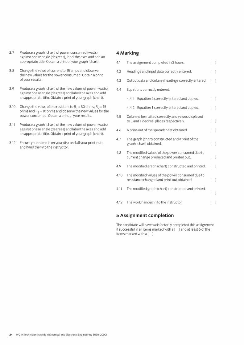
3.7 Produce a graph (chart) of power consumed (watts)against phase angle (degrees), label the axes and add anappropriate title. Obtain a print of your graph (chart).
3.8 Change the value of current to 15 amps and observe the new values for the power consumed. Obtain a print of your results.
3.9 Produce a graph (chart) of the new values of power (watts)against phase angle (degrees) and label the axes and addan appropriate title. Obtain a print of your graph (chart).
3.10 Change the value of the resistors to R1 = 30 ohms, R2 = 15ohms and R3 = 10 ohms and observe the new values for thepower consumed. Obtain a print of your results.
3.11 Produce a graph (chart) of the new values of power (watts)against phase angle (degrees) and label the axes and addan appropriate title. Obtain a print of your graph (chart).
3.12 Ensure your name is on your disk and all your print-outsand hand them to the instructor.
4 Marking
4.1 The assignment completed in 3 hours. ( )
4.2 Headings and input data correctly entered. ( )
4.3 Output data and column headings correctly entered. ( )
4.4 Equations correctly entered.
4.4.1 Equation 2 correctly entered and copied. [ ]
4.4.2 Equation 1 correctly entered and copied. [ ]
4.5 Columns formatted correctly and values displayed to 3 and 1 decimal places respectively. ( )
4.6 A print-out of the spreadsheet obtained. [ ]
4.7 The graph (chart) constructed and a print of the graph (chart) obtained. [ ]
4.8 The modified values of the power consumed due tocurrent change produced and printed out. ( )
4.9 The modified graph (chart) constructed and printed. ( )
4.10 The modified values of the power consumed due toresistance changed and print-out obtained. ( )
4.11 The modified graph (chart) constructed and printed.( )
4.12 The work handed in to the instructor. [ ]
5 Assignment completion
The candidate will have satisfactorily completed this assignmentif successful in all items marked with a [ ] and at least 6 of theitems marked with a ( ).
IVQ in Technician Awards in Electrical and Electronic Engineering 8030 (2000)24

1 Competence references
211.23 – 211.32
2 Preparation
2.1 Location of testThe training centre or other venue where supervision andappropriate working conditions will be provided.
2.2 RequirementsComputer system providing access to word processingsoftware and printer.Word processing software user manual.Headed paper suitable for the printer.Copy of section 6.
2.3 Instructor notesIn this assignment the dimensions (for margins, etc) areexpressed in centimetres. If different units are required,the candidate’s instructions must be modified accordingly.Instructions for setting tabs should be amended ifnecessary to match the position of the printed companyaddress on the headed paper to be used.
3 Candidates’ instructions
3.1 The time allowed for this assignment is 2 hours. In thisassignment you are required to produce a business letter(see section 6) and lay it out in a suitable style.
You are advised to read all of the instructions beforecommencing work. Ensure that you understand all theinstructions and follow them precisely. If you are in anydoubt ask the instructor.
3.2 Set the following margins and justification:
3.2.1 a left margin of 3 cm. and a right margin of 2.5 cm
3.2.2 justification to full
3.2.3 set appropriate tabs to display list of printers.
3.3 Produce the letter (see section 6) in a suitable business style.
3.4 Type in today’s date.
3.5 Make the heading Order Number CC145 bold.
3.6 Use the tabs to display the list of printers.
3.7 Use italics for the text taken from Printing News.
3.8 Use the spell check to check the spelling of your letter.
3.9 Save the document with a suitable filename and print it out.
3.10 Make the following changes to your letter:
3.10.1 set the justification to left aligned
3.10.2 change the font to an alternative appropriate font
3.10.3 change the font size by two points (eg 10 point to 12 point)
3.10.4 save and reprint the letter.
3.11 Write your name on the print-outs of the letters and handthem in to your instructor.
211 Computer Aided CommunicationPractical assignment 211/3: Word Processing – A Business Letter
Syllabus: 2000 edition 25

4 Marking
4.1 Assignment completed in 2 hours. ( )
4.2 Following specification met:
4.2.1 left and right margins set correctly [ ]
4.2.2 justification set correctly [ ]
4.2.3 tabs set appropriately. [ ]
4.3 Business letter produced with suitable layout. [ ]
4.4 Today’s date entered. ( )
4.5 Heading made bold. [ ]
4.6 Printers displayed in tab format. [ ]
4.7 Italics used for text taken from Printing News. [ ]
4.8 Spell check carried out. [ ]
4.9 File saved with a suitable filename and printed onheaded paper. [ ]
4.10 The following changes made to the letter:
4.10.1 justification left aligned [ ]
4.10.2 font changed [ ]
4.10.3 font size changed by 2 points [ ]
4.10.4 letter saved and reprinted. [ ]
4.11 Print-outs handed in. [ ]
5 Assignment completion
The candidate will have satisfactorily completed this assignmentif successful in all items marked with a [ ].
A period of seven days must elapse before an unsuccessfulcandidate may retake this assignment.
6 Assignment documentation
Please send the letter to:
Mr D Green, Carlton Computers plc, 14 Milton Road, Ashford, Kent TN28 1UR
Text of letter:
Dear ....
Order Number CC145
With reference to your order received today, I am writing to inform you that the Printer X1 50 is not available at present. I suggest you replace the printer with one of the models listed below:
No 1233A Printer X2 50 $200.00No 1334A Printer X2 100 $250.00No 1335B Printer X3 100 $300.00
The alternative is to take up the special offer available from January 1 in Printing News which states that customers can ‘return their current printerX2 50 in part exchange for the later model Printer X2 100 or the colour printer X3 100.Customers who are interested, please contact Mr Jones at Head Office on 144 0171 288 7777’.
Please contact me if you need further assistance.
Yours ....
(Type your own name at the bottom of the letter and sign it)
IVQ in Technician Awards in Electrical and Electronic Engineering 8030 (2000)26

Introduction
This unit aims to provide a broad coverage of both analogue and digital electronics. An approach, with worked examples and calculations where appropriate, based on hands-on practical work is recommended. Where possible, candidatesshould be introduced to the uses of discrete component andintegrated circuits in a range of small signal and large signalpractical applications.
Practical competences
The candidate must be able to do the following:
212.1 Design, construct and test a single stage transistoramplifier based on or incorporating either a bipolarjunction transistor (BJT) or field effect transistor (FET).Test: measure dc voltages, determine the voltage gain, frequency response and maximum signal handling capability
212.2 Build and test a power amplifier incorporating integrated circuits.Test: mid band voltage gain, frequency response, measure ac power output, dc supply power, calculateconversion efficiency
212.3 Observe the effects of wave shaping networks on ac signals.Signals: sine wave, square wave
Knowledge requirements
Instructors must ensure that candidates are able to:
Integrated circuits212.4 Describe the construction and operation of basic
analogue and digital IC circuits in both bipolar and FETforms including CMOS.Circuits: differential pair, complementary pair, dcfeedback pair, NAND/NOR logic gates
212.5 Identify from manufacturers’ data a range of integrated circuits.Integrated circuits: operational amplifiers,combinational sequential logic gates, regulators
212.6 State the scale of integration relating to integratedcircuits and identify appropriate applications of each.Scale and applications: SSI (basic logic gates), MSI(counters and shift registers), LS I(RAM and ROM), VLSI(microprocessors eg 6502, Z80), SLSI ( Pentium)
212.7 Explain the use of active devices as current sources andsinks in integrated circuits.
Signal shaping and coupling circuits212.8 Describe, with the aid of waveform sketches, the
operation of capacitor resistor (CR) circuits and theeffects of the time constant on both square wave andsine wave input signals.Circuits: differentiating, integrating
212.9 Determine by calculation and graphically the signalattenuation, phase shift and frequency response oftypical CR coupling circuits with sine wave inputs.
212.10 Sketch voltage waveforms to show the effect of junctiondiodes and voltage reference diodes (Zener), used inconjunction with suitable biasing voltages, to formshaping and clamping circuits.
Basic transistor circuits212.11 Describe briefly the construction and operation of
transistor bipolar junction transistors (BJT) and fieldeffect transistors (FET).
212.12 Explain how the dc operating conditions of commonsource and common emitter amplifier circuits areestablished and stabilised by use of current and voltagefeedback biasing.
212.13 Describe the operation of transistors as a switch and thelimiting conditions.Transistors: BJT, FETLimiting conditions: saturation, cut-off
212.14 Describe briefly the causes of switching delays in atransistor switching circuit.Causes: stored charge, transfer of charge
212.15 Calculate the dc voltage and current levels establishedby the use of current feedback biasing in single stageamplifier circuits.Circuits: common emitter bipolar transistor, commonsource field effect transistor
212.16 Explain the terms ‘small signal’ and ‘large signal’operation of a transistor.
212.17 Define the ac ‘small signal’ parameters for a bipolartransistor in common emitter configuration.Parameters: forward current ratio (hfe), input resistance (hie)
212.18 Define the ac ‘small signal’ parameters for a field effecttransistor in common source configuration.Parameters: forward transfer conductance (gfs or gm),output resistance (gos or 1/r0)
212.19 Calculate, using simplified ac equivalent circuits, thevoltage gains of single stage amplifier circuits.Circuits: common emitter, common source
212 Electronics
Syllabus: 2000 edition 27

212.20 Compare the performance of bipolar and field effecttransistor amplifiers using the results obtained in 212.19.
Basic amplifier circuits212.21 Describe the operation of a single stage transistor
amplifier circuit.Circuit: common emitter (BJT), common source (FET)
212.22 Explain the occurrence of signal distortion under theClass A operation.
212.23 Calculate the voltage and current gains of two stageamplifiers using the appropriate equivalent circuits andtypical device parameters.Amplifiers: common emitter, common sourceDevices: bipolar transistor, field effect transistor
212.24 Sketch typical ‘small’ signal frequency response curves (gain in dB against logarithmic frequency) for an amplifier and state the reasons for the fall in gain at low and high frequencies.
212.25 Define bandwidth as the frequency band between thetwo frequencies where the gain of an amplifier has fallenby 3dB from its mid band value.
212.26 Explain briefly the various modes (classes) of operationused in amplifiers.Modes: A, B, C, D
Feedback212.27 Describe briefly, using block diagrams, the basic
principles of positive and negative feedback.
212.28 Define feedback factor and calculate the gain of anamplifier having a negative feedback loop with afeedback factor .
212.29 Explain the effects of negative feedback.Negative feedback: reduces noise, reduces distortion,stabilizes gain, modifies bandwidth, modifies input andoutput impedances
212.30 Describe the types of negative feedback and comparetheir performances.Performance: voltage gains (Av), current gain (Ai), inputimpedance (Z1n),output impedance (Z0)Types: series, parallel, voltage, current
212.31 Describe briefly the operation of simple single stagenegative feedback amplifier circuits and determine theirapproximate gain.Circuits: unbypassed emitter (or source) resistor,emitter (or source follower), voltage feedback fromoutput to input
Oscillators212.32 Define oscillators as general feedback amplifiers with
positive (regenerative) feedback.
212.33 State the conditions for sine wave oscillations to be generated.Conditions: gain must be infinite, loop gain must be 1,must occur at a single frequency
212.34 Describe the operation of a 3-stage RC phase shift oscillator.
212.35 Describe with the aid of a circuit diagram, the operationof a single tuned-circuit oscillator.
212.36 Perform calculations of gain and frequency of RC andtuned-circuit oscillators.
212.37 State the frequency range of RC and LC oscillators.Frequency range: RC – low frequency and audio, LC – high frequency
212.38 State the advantages of using crystal control in oscillators.Advantages: preset frequencies, high stability
Operational amplifiers212.39 State the characteristics of a typical operational amplifier.
Characteristics: open loop gain is high, input resistance is high, output resistance is low, gain bandwidth product is 1 MHz
212.40 Sketch the open loop response of a typical operationalamplifier and show how this is modified by negativefeedback to produce a constant gain bandwidth product.
212.41 Sketch the circuits and describe the operation of a rangeof operational amplifier circuits incorporating resistorcapacitor networks.Amplifiers: integrator, ac coupled amplifier having ahigh-pass frequency response, dc amplifier having a lowpass frequency response
212.42 Calculate the mid band voltage gains and bandwidths ofthe high-pass and low-pass operational amplifier circuitsgiven typical component values.Amplifiers: ac coupled amplifier having a high-passfrequency response, dc amplifier having a low-passfrequency response
Basic logic circuits212.43 Explain, using truth tables, the operation of a range of 2
input logic gates.Logic gates: AND, OR , NAND, NOR, XOR
212.44 Reduce simple Boolean expressions using logicalrelationships.
212.45 Construct combinational gate systems to implementsimple Boolean expressions or truth tables.
IVQ in Technician Awards in Electrical and Electronic Engineering 8030 (2000)28

212.46 Explain the need for a latch.
212.47 Draw the circuit and explain the operation of a simple RS latch.
212.48 Explain with the aid of a logic diagram the operation ofthe cross-coupled NAND or NOR gates.
Power output circuits212.49 Compare efficiencies of a range of amplifiers.
Amplifiers: Class A, Class AB, Class B
212.50 Describe typical applications for the range of amplifiersin 212.49 above.
212.51 Explain, with the aid of a diagram, the operation of a ClassB push-pull amplifier (using complementary transistors).
212.52 State the effect of cross-over distortion and explain howit can be eliminated.
212.53 Explain, with the aid of a diagram, the operation of a Class AB push-pull amplifier incorporating abootstrap capacitor.
212.54 Using manufacturers’ data sheets, select a range ofpower ICs for given applications, eg LM380, TDA2030.
Use of instruments212.55 Explain the functions of the main controls of
an oscilloscope.Controls: channel gain, time base speed, sync/trigger,time base mode (alternate scan or switching)
212.56 Describe applications of the oscilloscope.Applications: waveform observation, measurement ofamplitude, time, frequency and phase
212.57 Describe the use of probes to improve the performance of oscilloscopes and electronicinstruments at high frequencies.Types of probe: low capacitance, multiplier, rectifier
212.58 Define the terms ‘resolution’ and ‘accuracy’ ofinstruments and determine typical values frommanufacturer’s data.
212.59 Calculate errors in instrument readings and thetolerance which must be applied arising from practical limitations.Limitations: loading due to instrument impedance,resolution and accuracy of the instrument
212.60 Describe the operation and use of a simple logic probe.
Optoelectronics212.61 Explain that light energy generates electron-hole pairs
in a semiconductor.
212.62 Describe briefly the construction and operation of arange of photo sensitive devices.Devices: photo resistive cells (light-dependent resistors – LDR), photovoltaic cells (solar cells), photodiodes, photo transistors
212.63 Compare the relative merits of a range of photo sensitive devices.Merits: cost, size, linearity, dynamic range, speed,temperature sensitiveDevices: light dependent resistors, solar cells, photodiodes and transistors
212.64 Describe typical applications of photo sensitive devices.Typical applications: light operated relay, powersource (solar cell), light meter, light sensitive switch
212.65 Describe the emission of light generated by passingcurrent through a forward biased junction (light emittingdiode – LED).
212.66 Determine, using manufacturers’ or suppliers’information, details of commercially available lightemitting diodes.Details: emission colour, forward voltage, maximumcurrent and power ratings, size
212.67 Sketch circuits for the operation of various LEDs andcalculate suitable component values from theinformation obtained in 212.66.
212.68 Describe briefly the construction and operation of anopto-isolator and state typical applications.Applications: completely isolated non-electricalcoupling, switching high voltage loads from sensitivelow voltage sources
212.69 Describe the principle of light propagation along a fibreoptic cable and explain the associated terms.Terms: step index, graded index
212.70 Sketch a simple block diagram and describe theoperation of a fibre optic communication system.System: transmission, receiver, fibre optic cable
Syllabus: 2000 edition 29

Test specification for written paperElectronics (8030-22-212)
This is a written examination paper lasting three hours with tenquestions. Candidates must answer all questions.
The examination will cover the knowledge specifications:
Approximate %examination
Topic weighting
Integrated circuits 5
Signal shaping and coupling circuits 5
Basic transistor circuits 10
Basic amplifier circuits 15
Feedback 10
Oscillators 10
Operational amplifiers 5
Basic logic circuits 10
Power output circuits 10
Use of instruments 10
Optoelectronics 10
Assessment
IVQ in Technician Awards in Electrical and Electronic Engineering 8030 (2000)30

1 Competence references
212.3
2 Preparation
2.1 Location of testThe training centre or other venue where supervision andappropriate working conditions will be provided.
2.2 Components: wave shaping networks as shown in section6, figure 1a, 1b and 1c mounted on a suitable test board.
Test equipment: function generator, 2-channeloscilloscope and suitable test leads.
Support facilities: drawing and writing materials, copy ofsection 6.
2.3 Instructor notesCandidates are required to connect up the networks insection 6, observe the effects of wave shaping networks onac signals, record the results and explain the operation ofthe networks.
Candidates have 3 hours to complete this assignment.
Instructors must ensure that health and safety regulationsare observed at all times.
3 Candidates’ instructions
3.1 You have three hours to complete this assignment. In this assignment you are required to:
• observe the effects of wave shaping networks on ac signals
• record all results• explain the operation of the networks.
3.2 Signal connections and test procedures
3.2.1 Connect, in turn, each of the networks shown insection 6, figures 1a, 1b and 1c to a signal generatorand oscilloscope as shown in figure 2.
3.2.2 For network 1a, set the function generator to give a1kHz sinewave having an amplitude of 24V peak topeak. This waveform is monitored on channel 1 ofthe oscilloscope.
3.2.3 Observe the output waveform of the network onchannel 2 of the oscilloscope.
3.2.4 Sketch the shape of the waveform and record thevoltage levels of both the negative and positivepeaks measured with respect to zero volts of dc.
3.2.5 Replace network 1a with network 1b and repeatsteps 3.2.3 and 3.2.4 keeping the same input signal.
3.2.6 Replace network 1b with network 1c and changethe input signal setting to a 1kHz square wavehaving an amplitude of 20V peak to peak. Repeatsteps 3.2.3 and 3.2.4.
3.3 Conclusions
3.3.1 For the networks, explain the reasons for theshapes of the output waveforms and the associatedvoltage levels.
3.3.2 Write your name on your work and hand it in to yourinstructor.
213 Electronics Practical AssignmentsPractical assignment 213/1: Wave Shaping
Syllabus: 2000 edition 31

4 Marking
4.1 Assignment completed in three hours. ( )
4.2 Signal connections and test procedures
4.2.1 Each of the networks shown in section 6, figures 1a, 1b and 1c connected in turn to a signal generator and oscilloscope as shown in figure 2. [ ]
4.2.2 For network 1a, the function generator set to give a 1kHz sinewave having an amplitude of 24V peak to peak. This waveform monitored on channel 1 of the oscilloscope. [ ]
4.2.3 Observation of the output waveform of the network on channel 2 of the oscilloscope. [ ]
4.2.4 The shape of the waveform sketched and thevoltage levels recorded of both the negative and positive peaks measured with respect to zero volts of dc. [ ]
4.2.5 Network 1a replaced with network 1b and steps 3.2.3 and 3.2.4 repeated, keeping the same input signal. [ ]
4.2.6 Network 1b replaced with network 1c and the input signal setting changed to a 1kHz square wave having an amplitude of 20V peak to peak. Steps 3.2.3 and 3.2.4 repeated. [ ]
4.3 Conclusions
4.3.1 For the networks, explanation given for the reasons for the shapesof the output waveforms and the associated voltage levels. [ ]
4.3.2 Name written on work and handed in to instructor. [ ]
5 Assignment completion
The candidate will have satisfactorily completed this assignmentif successful in all the items marked with [ ].
A period of several days must elapse before an unsuccessfulcandidate may retake this assignment. An alternative circuitdesign should be used.
IVQ in Technician Awards in Electrical and Electronic Engineering 8030 (2000)32

6 Assignment documentation
6.1 Wave shaping
Syllabus: 2000 edition 33

1 Competence references
212.1
2 Preparation
2.1 Location of testThe training centre or other venue where supervision andappropriate working conditions will be provided.
2.2 RequirementsComponents: Range of electronic components: 1transistor, 4 resistors and 2 capacitors. Suitable circuitboard, strip board or printed circuit board.
Tools: kit of small tools and soldering iron for electronicassembly. Resin-cored solder.
Test equipment: dc power supply, multimeter (analogue ordigital), audio signal generator, 2-channel oscilloscope andsuitable test leads.
Support facilities: graph or squared paper, drawing andwriting materials. Transistor data sheet. Copy of section 6.
2.3 Instructor notesCandidates are required to design, build and test a singlestage junction transistor common emitter amplifier.
Candidates have 6 hours to complete this assignment.
Instructors must ensure that health and safety regulationsare observed at all times.
3 Candidates’ instructions
3.1 The time allowed for this assignment is 6 hours. You areadvised to read all the instructions before commencingwork. If you do not understand all the instructions thenplease ask your instructor.
In this assignment you are required to identify thecomponents (see circuit diagram section 6), solder thecomponents to the matrix board to the layout in the circuit diagram.
3.2 List the components required from the diagram (section 6).
3.3 Plan the layout on graph (squared) paper and ensure thelayout is economical.
3.4 Check the layout is correct with your instructor.
3.5 Insert the components in the strip board and insert pins inappropriate holes in the board to anchor the components.
3.6 Solder the components to the pins to form the amplifiercircuit shown.
3.7 Power up circuit using 9 volt power supply unit (or battery).
3.8 Check dc levels throughout circuit and record the values.
3.9 Input 1 kHz signal from signal generator and display inputand output on an oscilloscope. Adjust input amplitude toavoid any distortion.
3.10 Draw the input signal and the output signal and measurethe amplitudes.
3.11 Calculate the voltage gain of the amplifier from the resultsobtained in 3.10.
3.12 Increase the input amplitude to a maximum value withoutcausing significant distortion and record the value.
3.13 Put your name on your work and hand it in to your instructor.
213 Electronics Practical AssignmentsPractical assignment 213/2: Design and Build a Common Emitter Transistor Amplifier
IVQ in Technician Awards in Electrical and Electronic Engineering 8030 (2000)34

4 Marking
4.1 Assignment completed in 6 hours. ( )
4.2 The components correctly listed.
4.3 The layout correctly and economically planned on graph (squared) paper. [ ]
4.4 The layout checked by the instructor. [ ]
4.5 The components inserted in the strip board and pins inserted in appropriate holes in the board to anchor the components. [ ]
4.6 The components soldered to the pins to form the amplifier circuit shown. [ ]
4.7 Circuit powered up using 9 volt power supply unit (or battery). [ ]
4.8 Dc levels checked throughout circuit and the values recorded. [ ]
4.9 Input 1 kHz signal input from signal generator and input and output signal displayed on an oscilloscope.Input amplitude adjusted to avoid any distortion. [ ]
4.10 The input signal and the output signal drawn and theamplitudes measured. [ ]
4.11 The voltage gain of the amplifier calculated from theresults obtained in 3.10. [ ]
4.12 The input amplitude increased to a maximum value without causing significant distortion and the value recorded. [ ]
4.13 Work handed in to instructor. [ ]
5 Assignment completion
The candidate will have satisfactorily completed this assignmentif successful in all the items marked with [ ].
A period of seven days must elapse before an unsuccessfulcandidate may retake this assignment. An alternative circuitdesign should be used.
Syllabus: 2000 edition 35
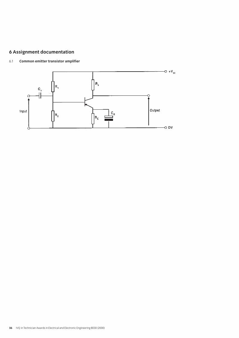
6 Assignment documentation
6.1 Common emitter transistor amplifier
IVQ in Technician Awards in Electrical and Electronic Engineering 8030 (2000)36

1 Competence references
212.2
2 Preparation
2.1 Location of testThe training centre or other venue where supervision andappropriate working conditions will be provided.
2.2 RequirementsComponents: 1 LM380 or equivalent, 2M2 logarithmicpotentiometer, 2R7 resistor, 8Ω 3 watt resistor, 470Felectrolytic capacitor, 100nF capacitor, suitable circuitboard with combined heat sink as advised by themanufacturers.
Tools: kit of small tools and soldering iron for electronicassembly, resin-cored solder.
Test equipment: 8Ω loudspeaker, crystal microphone, dcpower supply, multimeter (analogue or digital), audiosignal generator, 2-channel oscilloscope and suitable testleads.
Support facilities: drawing and writing materials, LM380 (orequivalent) data sheet, copy of section 6.
2.3 Instructor notesCandidates are required to construct the power amplifierin section 6, ensure that the circuit functions correctly,determine the maximum signal levels, mid band gain,overall frequency response, output power and conversionefficiency using appropriate instruments. Record resultsand show calculations. Candidates have 3 hours tocomplete this assignment.
Instructors must ensure that health and safety regulationsare observed at all times.
3 Candidates’ instructions
3.1 You have three hours to complete this assignment. In thisassignment you are required to assemble and test a singlestage integrated circuit power output amplifier.
Typical Specification:Power supply Vcc 20V d.c. (25V maximum)Quiescent current 7mAVoltage gain 50 (34dB)Input sensitivity 150mV rmsInput resistance 150 kWMaximum input voltage 0.5VLoad resistance 8WApproximate bandwidth 100kHz
3.2 Sketch a circuit diagram of the proposed amplifier. Seesection 6, Fig 1.
3.3 Select components.
3.3.1 Choose a suitable amplifier eg LM380, or similar,and refer to the data sheet for the device toestablish its specification.
3.3.2 Select the supply voltage Vcc
3.3.3 Select component values if different from the those shown in Fig 1.
3.3.4 Draw the circuit diagram showing the component values.
3.3.5 Draw up a component list for the proposed design.
3.3.6 Design a suitable circuit and component layout forthe type of construction to be used, eg strip boardor printed circuit board. Take care to include themanufacturers’ recommendations for the provisionof a heat sink.
3.4 Assemble the circuit using appropriate tools.
3.5 Inspect the assembled circuit and check for errors.Connect the circuit to a suitable power supply.
3.6 Carry out the following performance tests and record all results:
3.6.1 Check the supply voltage Vcc
3.6.2 Connect a loudspeaker across the output terminalsand a crystal microphone to the input of theamplifier. Speak into the microphone and vary thesetting of the volume control to test that theamplifier provides a satisfactory audio output.
213 Electronics Practical AssignmentsPractical assignment 213/3: Build and Test an Integrated Circuit Power Amplifier
Syllabus: 2000 edition 37

3.6.3 Replace the microphone and loudspeaker with asignal generator and 8W resistor respectively. Withthe input signal frequency set to 1kHz, at a levelsufficient to provide a significant output, free fromany obvious distortion, measure the input andoutput voltages using the oscilloscope. Calculatethe overall mid band voltage gain.
3.6.4 With the connections as in 3.6.3, increase the inputvoltage to determine the maximum availableundistorted output voltage and record the amplitudeof the input signal required to achieve this. Calculatefrom the amplitude of the output voltage, the acoutput power delivered to the 8W load.
3.6.5 Under conditions of maximum ac output power,measure the dc current taken from the powersupply and calculate (a) the dc power supplied tothe amplifier and (b) the conversion efficiency of the amplifier.
3.6.6 Reset the conditions as at 3.6.3, vary the inputsignal over a range of frequency and monitor thechange in the amplitude of the output voltage onthe oscilloscope to determine the bandwidth of the amplifier.
3.7 Write a test report to include design calculations, results obtained from the practical measurements and any observations.
3.8 Hand in your work to your instructor.
4 Marking
4.1 Assignment completed in three hours. ( )
4.2 A circuit diagram of the proposed amplifier sketched. ( )
4.3 Components :
4.3.1 A suitable amplifier selected [ ]
4.3.2 The supply voltage Vcc selected [ ]
4.3.3 Component values if different from the those shown in Fig 1 selected [ ]
4.3.4 Circuit diagram showing the component values drawn [ ]
4.3.5 A component list for the proposed design drawn up [ ]
4.3.6 A suitable circuit and component layout for the type of construction to be used designed [ ]
4.4 The circuit assembled using appropriate tools. [ ]
4.5 The assembled circuit inspected and checked for errors. The circuit connected to a suitable power supply. [ ]
4.6 The following performance tests carried out and results recorded:
4.6.1 The supply voltage Vcc checked [ ]
4.6.2 A loudspeaker connected across the outputterminals and a crystal microphone to the input of the amplifier. ( )
4.6.3 The microphone and loudspeaker replaced with a signal generator and 8W resistor respectively. With the input signal frequency set to 1kHz, the input and output voltagesmeasured using the oscilloscope. The overall mid band voltage gain calculated. [ ]
4.6.4 With the connections as in 4.6.3, the input voltage increased to determine the maximumavailable undistorted output voltage and theamplitude of the input signal required to achievethis recorded. From the amplitude of the output voltage, the ac output power delivered to the 8W load calculated. [ ]
IVQ in Technician Awards in Electrical and Electronic Engineering 8030 (2000)38

4.6.5 Under conditions of maximum ac output power, measure the dc current taken from the power supply measured and (a) the dc power supplied to the amplifier and (b) the conversion efficiency of the amplifier calculated. [ ]
4.6.6 The conditions as at 4.6.3 reset, the input signal over a range of frequency varied and the change in the amplitude of the output voltage on the oscilloscope to determine the bandwidth of the amplifier monitored. [ ]
4.7 A test report written. [ ]
4.8 Work handed in to the instructor. [ ]
5 Assignment completion
The candidate will have satisfactorily completed this assignmentif successful in all the items marked with [ ].
A period of several days must elapse before an unsuccessfulcandidate may retake this assignment.
Syllabus: 2000 edition 39

6 Assignment documentation
6.1 Integrated circuit power amplifier
IVQ in Technician Awards in Electrical and Electronic Engineering 8030 (2000)40

Introduction
This syllabus extends the range of fundamental power topics andconsolidates previous work on the fundamentals of dc machines,ac machines and transformers. It also covers the principles ofmeasurements and the distribution of electrical energy.
Practical competences
The candidates must be able to do the following:
214.1 Carry out and record earth electrode and soil resistivity tests.
214.2 Investigate and record a metering installation for smallindustrial/commercial premises.
214.3 Investigate and record the basic layout of the systemand types of equipment used in industrial/commercialdistribution systems.
Knowledge requirements
Instructors must ensure that candidates are able to:
Testing and Measurement214.4 Show with the aid of a labelled circuit diagram how a
dynamometer wattmeter is connected in circuit.
214.5 Show with the aid of a labelled circuit diagram how a single wattmeter may be used to measure the power per phase in ac loads.Loads: balanced, three-phase, star-connected, delta-connected
214.6 Show with the aid of a labelled circuit diagram how two-wattmeters may be used to measure the total power in athree-phase, three-wire load.
214.7 Calculate the total power measured by the two-wattmeter method from the algebraic sum of thewattmeter readings (P1 and P2).
214.8 Determine the phase angle of a balanced three-phaseload by the two-wattmeter method
using the expression tan = √–3 ( )
214.9 Explain, with the aid of a diagram, how power and powerfactor may be measured in a single-phase circuit, using avoltmeter, an ammeter and a wattmeter.
214.10 Explain, with the aid of a diagram, how the range ofinstruments may be extended by the use of current andvoltage transformers.
214.11 Solve problems in power measurement including errorsinherent in the method of connecting the wattmeter.
214.12 Explain the use for specialised instruments when testing electrical installations and state typicalacceptable values.Instruments (testing): continuity and insulationresistance, earth fault loop and residual current device (RCD) tester.
214.13 Describe how earth electrode resistance may be measured.
214.14 Sketch a diagram of the complete earth-loop path andexplain the meaning of earth fault loop impedance.
214.15 Explain, with the aid of a diagram how the earth-loopimpedance is measured.
214.16 Explain typical metering requirements for a smallindustrial installation.Requirements: energy, maximum demand, kVA, power factor
214.17 Describe, with the aid of a diagram, how meters areconnected to meet the requirements in 214.16
Transmission and Distribution214.18 State the advantages and disadvantages of alternating
current for the generation, transmission and distributionof electrical energy.
214.19 Sketch a single-line diagram of a typical three-phasesupply system from generator to consumer terminals.
214.20 State the advantages and disadvantages of variousdistribution systems.Systems: radial, closed ring, open ring
214.21 Explain why transformers are used in transmission anddistribution systems.
214.22 Describe, with the aid of diagrams, the difference in usebetween three-wire and four-wire three-phase systems.
214.23 Describe, with the aid of diagrams, the principles andmethods of earthing of supply systems.Systems: TN, TN-C, TN-S, TN-C-S, TT, IT
214.24 Describe, with the aid of a diagram, a smallindustrial/commercial distribution system.
214.25 Describe factors influencing the choice of cable forparticular applications.Factors: installation, environmental
214.26 State advantages and disadvantages of materialscommonly used for cable conductors, insulation and sheathing.
P2 –P1
P2+P1
214 Electrical Power
Syllabus: 2000 edition 41

214.27 Define the term ‘dielectric stress’.
214.28 Describe methods of stress control in high voltagecables and cable terminations.Methods: grading, intersheathing
214.29 Describe the function of types of switchgear used indistribution systems.Types of switchgear: circuit breaker, disconnector(isolator), oil switch, switch fuse
214.30 Describe the basic methods of arc control in circuitbreakers.Methods: oil, air vacuum
214.31 Describe the advantages and disadvantages of fuses forsystem protection.
214.32 Define the term ‘fusing factor’.
214.33 State the advantages and disadvantages of relays forsystem protection.
214.34 Describe the principle of operation of an inverse definiteminimum time (IDMT) protection relay.
214.35 Describe a simple over current and earth fault protectionsystem for a circuit.
Power Factor Improvement214.36 Explain the disadvantages of low power factor both from
the consumer and the supplier’s point of view.
214.37 Describe methods of power factor improvement forindividual loads and for overall systems.Methods: static capacitor, synchronous machine
214.38 Calculate kVAr ratings and capacitance of capacitorsneeded to improve lagging power factor.
214.39 Describe typical tariff structures for individualconsumers.
214.40 Calculate from given tariff structures the cost benefit ofpower factor improvement.
DC Machines214.41 Describe, with the aid of diagrams, the principles of
operation of a dc machine both in the generator andmotor mode.
214.42 Derive the e.m.f. equation for a dc machine E = kN .
214.43 Sketch circuit diagrams for field connections of dc machines.Connections: separately excited shunt, series,compound-wound machines
214.44 Derive the voltage equation V = E ± IaRa for eachconnection and each mode of operation.Mode: generator, motor
214.45 Derive the speed and torque equations for a dc machine in
the form T = k Ia and N = .
214.46 Use voltage, speed and torque equations to obtainthe terminal voltage/load characteristic for each type of dc generator.Generators: shunt, series, compound, separately excited
214.47 Use the voltage speed and torque equations to obtain the speed/load torque characteristic for eachtype of dc motor.Types of motor: separately excited, shunt, series and compound
214.48 Describe the process of self-excitation for a dc machineoperating as a generator.
214.49 Determine graphically the terminal voltage of a dc shuntgenerator from an excitation characteristic and a fieldresistance line.
214.50 Define the term ‘critical field resistance’.
214.51 Describe the various forms of loss occurring in a dc machine.Forms of loss: armature, field, winding
214.52 Solve problems on dc motors and generators.
214.53 Describe methods of varying output voltage of dc generators.
214.54 Describe methods of varying the speed of dc motors andexplain their limitations.
214.55 Solve problems associated with varying output voltageand speed of dc machines.
214.56 Explain the need for motor starters.
214.57 Explain, with the aid of diagrams, armature reaction andcommutation in dc machines.
214.58 Describe methods used to overcome the effect ofarmature reaction on commutation.Methods: use of interpoles, moving brush gear
AC Machines214.59 Explain the production of a rotating magnetic field when
a suitable three-phase supply is connected to the statorwinding of a three-phase machine.
Ek
IVQ in Technician Awards in Electrical and Electronic Engineering 8030 (2000)42

214.60 Describe with the aid of sketches, the construction of athree-phase cage- and wound-rotor induction machine.
214.61 Describe, with the aid of diagrams, the principle ofoperation of a three-phase induction motor.
214.62 Define and calculate values of synchronous speed, slipand slip speed.
214.63 Sketch the torque/speed characteristic for a typicalthree-phase cage-rotor induction motor, showingstarting torque, maximum torque and rated torque.
214.64 Explain the conditions for maximum torque in aninduction motor.
214.65 State that the starting current is 5 to 7 times the full loadvalue for a typical three-phase cage rotor inductionmotor.
214.66 Explain the reason for connecting resistance in the rotorcircuit when starting wound rotor induction motors.
214.67 Sketch a family of torque/speed characteristics showingthe effect of varying the total rotor circuit resistance.
214.68 Solve problems concerning stator and rotor losses andefficiency for induction motors.
214.69 Describe, with a circuit diagram, a basic direct-on-linestarter with no volt release provision and overloadprotection for a three-phase induction motor.
214.70 Explain why reduced voltage is used for starting large induction motors.
214.71 Describe methods of starting three-phase induction motors.Methods: star-delta, autotransformer
214.72 Describe, with the aid of a sketch, the construction of a three-phase synchronous machine with a range of rotors.Rotors: salient pole, cylindrical
214.73 Describe, with the aid of sketches, the principal modesof operation of synchronous three-phase machines.Modes: generator, motor
214.74 Explain why a synchronous motor is not self starting.
214.75 Describe typical applications for cylindrical rotor andsalient-pole rotor synchronous generators and motors.
214.76 Describe, with the aid of a sketch, the construction of asingle-phase cage rotor induction motor.
214.77 State that a single-phase cage rotor induction motor isnot self starting but if rotated in either direction willaccelerate to load speed.
214.78 Describe the principle of operation of the split-phasesingle-phase induction motor.
214.79 Sketch the torque/speed characteristic for a typical split-phase, single-phase induction motor.
Transformers214.80 Describe with the aid of sketches the construction of a
typical transformer and the types of winding.Construction: core, shellWinding: disc, helical, layer, sandwich
214.81 Show that, for an ideal transformer = =
214.82 Sketch and explain the no-load phasor diagram of a transformer.
214.83 Sketch a phasor diagram for given values of no-load(primary) current and power factor, and secondarycurrent and power factor.
214.84 Calculate primary current and power factor from given data.
214.85 Sketch and explain the transformer equivalent circuit forload conditions.
214.86 State the losses for no-load and load conditions.
214.87 Explain the reasons for laminating the core of a transformer.
214.88 Describe open-circuit and short-circuit tests and theiruse in determining losses and efficiency.
214.89 Solve problems for transformers involving losses andefficiency using open-circuit and short circuit test data.
214.90 Define ‘voltage regulation’.
214.91 Calculate voltage drop and regulation for various loadsat lagging power factors.
214.92 Describe how a transformer winding can be ‘tapped’ toprovide various voltage outputs.
214.93 Describe, with the aid of diagrams, the principle ofoperation of an autotransformer.
214.94 Describe suitable uses for an autotransformer.
214.95 Describe the advantages and disadvantages ofautotransformers in relation to double woundtransformers.
IsIp
NpNs
EpEs
Syllabus: 2000 edition 43

Test specification for written papersElectrical Power (8030-22-214)
This is a written examination paper lasting three hours with tenquestions. Candidates must answer all questions.
The examination will cover the knowledge specifications:
Approximate %examination
Topic weighting
Testing and measurement 14
Transmission and distribution 20
Power factor improvement 8
DC Machines 20
AC Machines 20
Transformers 18
Assessment
IVQ in Technician Awards in Electrical and Electronic Engineering 8030 (2000)44

1 Competence references
214.1
2 Preparation
2.1 Location of testsThe training centre or other venue where supervision andappropriate outdoor work area will be provided
2.2 Requirements1 Earth tester (megger or equivalent)4 Earth rods (or steel rods) approximately 1.2 metres longand 16 mm diameter4 Steel rods 0.5m long and 10mm diameter1 Set of connecting leads and clamps1 1 kg or 2 kg hammerPens, pencils, paper and graph paper
2.3 Instructor notesCandidates may undertake the work in pairs, providedresults and analysis is carried out independently.Candidates have 3 hours to complete this assignment.
2.4 Instructor instructionsThe proposed outdoor work site should be checked toensure that there are no buried services which could bedamaged.
It may be useful for the instructor to demonstrate eachprocedure before allowing candidates to proceed.
215 Electrical Practical AssignmentsPractical assignments 215/1: Earth Electrode and Soil Resistivity Tests
Syllabus: 2000 edition 45

3 Candidates’ instructions
3.1 The time allowed for this assignment is 3 hours. You are required to carry out and record earth electrode and soil resistivity tests, plot graphs obtained from these tests and describe/explain aspects of these tests. You are advised to read all the instructions before commencingwork. If you do not understand all the instructions thenplease ask your instructor.
3.2 Earth electrode tests
Read the manufacturer’s instructions for the Earth Testerto establish connections. A typical connection diagram isshown below:
Drive one earth rod 0.3 metre into the ground, to be usedas the test electrode. Using two 0.5m steel rods, place oneat 20m and one at 30m from the test electrode. Drive eachsteel rod 0.3m into the ground. Connect the terminals onthe earth tester to the earth electrode and steel rods usingconnecting leads and clamps. Ensure that all connectionsare clean and tight.
3.2.1 Use the earth tester to obtain the earth resistanceof the electrode. Record the value.
3.2.2 Repeat the test with the test electrode driven in0.4m, 0.5m, 0.6m and 0.8m into the ground.
3.2.3 Drive a second earth rod 0.8m into the ground, 1.5mfrom the first test electrode. Connect the two rodstogether using connecting wire and clamps. Testthe new installation and record the value of earthresistance obtained.
3.2.4 Repeat earth tests similar to (3.4) using three andthen four earth rods.
3.3 Plot a graph of the results obtained in tests 3.2 - 3.3.
3.4 Describe how the earth electrode resistance varies withthe depth of the electrode.
3.5 Plot a graph of the results obtained for 1, 2, 3 and 4electrodes each driven 0.8m into the ground.
IVQ in Technician Awards in Electrical and Electronic Engineering 8030 (2000)46

3.6 Describe how the earth electrode resistance varies withthe number of earth rods connected in parallel.
3.7 Soil resistivity
Read the instructions for the Earth Tester being used toascertain connections. A typical circuit for the test isshown below:
3.7.1 Drive four 0.5m steel rods 0.3m into the ground in astraight line, spaced at 10m intervals. Connect theleads to the rods using clamps, ensuring allconnections are clean and tight. Use the earthtester to obtain the value of earth resistance.Record the results.
3.7.2 Drive the rods 0.4m into the ground and repeat thetest. Repeat the test at a different location wherethe ground is either wetter or drier.
3.8.1 Calculate the value of soil resistivity for each testusing the formula:
Resistivity = 2 a R ohm-cm, where a = spacingbetween steel rods in cms and R = earth resistancein ohms
3.8.2 Using the value of soil resistivity obtained, calculatethe theoretical earth electrode resistance for asingle electrode using the formula:
Resistance = x
where l is the length of the earth rod in the ground in metres and dis the diameter of the earth rod in mm.
Compare this with the value obtained in the above practical tests.
3.9 Explain why soil resistivity may vary and how this wouldaffect the site chosen for an earth electrode installation.
3.10 Describe TWO other methods of earthing other than usingseveral eardi rods in parallel.
3.11 Ensure that you hand in all your work (records, graphs etc)in to your instructor.
Log10 (4000 x 1)d
Resistivity (ohm-cm)250 x 1
Syllabus: 2000 edition 47

4 Marking
4.1 Assignment completed in 3 hours. ( )
4.2 Earth resistance tests carried out correctly. [ ]
4.3 Graph of results for tests 3.2.2 and 3.2.3 plotted correctly. ( )
4.4 Description of how earth resistance varies with depth of electrode given. ( )
4.5 Graph of results for 1, 2, 3 and 4 electrodes plotted correctly. ( )
4.6 Description of how earth resistance varies with thenumber of earth rods in parallel given. ( )
4.7 Soil resistivity tests carried out correctly. [ ]
4.8.1 Soil resistivity values calculated for each test. [ ]
4.8.2 Theoretical value of earth electrode resistance calculated and compared with value from practical test. [ ]
4.9 Explanation of why soil resistivity may vary and its effect on the choice of earthing site given. [ ]
4.10 Descriptions of other methods of earthing given. [ ]
4.11 Work handed in to the instructor. [ ]
5 Assignment completion
The candidate will have satisfactorily completed this assignmentif successful in all items marked with a [ ] and at least 2 of theitems marked with a ( ).
A period of seven days must elapse before an unsuccessfulcandidate may retake this assignment.
IVQ in Technician Awards in Electrical and Electronic Engineering 8030 (2000)48

1 Competence references
214.2
2 Preparation
2.1 Location of assignmentThe training centre or other venue where supervision andappropriate working conditions will be provided.
2.2 RequirementsPens, pencils, clipboard and paper
2.3 Instructor notesCandidates may undertake the work in small groups,provided the report on the system investigated is writtenup independently. The candidates will need to be able tostudy the metering installed within the training centre or ata small engineering or commercial premises.
Installation selected must include meters for the following purposes:
Total energy consumedMaximum demandkVAPower factor
2.4 Instructor instructionsA visit to a metering installation must be arranged. Thiscould be within the training centre or at a local commercialor industrial premise, providing the requirements in 2.3 are satisfied.
If a visit to a suitable installation is impractical, a simulatedinstallation may be used.
Health and Safety issues must be explained to candidatesin relation to electrical and other hazards which may bepresent on site.
Writing up the assignment may be done outside the 2 hourpractical session.
3 Candidates’ instructions
3.1 The time allowed for this assignment is 2 hours. You areadvised to read all the instructions before commencing thework. If you do not understand all the instructions thenplease ask your tutor.
3.2 A visit will be arranged for you to study a meteringinstallation at a small engineering or commercial premises.You will be required to investigate and record details of themetering arrangement and connections.
You must not touch any part of the wiring during the visit.
3.3 Sketch the layout of the metering installation.
3.4 Draw a wiring diagram for the installation showing howeach meter is connected to the supply.
3.5 Explain the function of each meter and why it is necessary.
3.6 Explain why a customer may benefit by reducing themaximum demand they make on the supply system andhow this could be achieved without reducing the amountof electrical equipment installed.
3.7 Explain the benefit to the supplier of reducing maximumdemand without reducing overall consumption.
3.8 Explain the disadvantages of low power factor both to thesupplier and the customer.
3.9 Hand in work to the instructor.
215 Electrical Practical AssignmentsPractical assignments 215/2: Metering Installations for Small Industrial/ Commercial Premises
Syllabus: 2000 edition 49

4 Marking
4.1 Assignment completed in 2 hours (excluding write-up). ( )
4.2 Layout of meters sketched correctly. [ ]
4.3 Wiring diagram drawn correctly. [ ]
4.4 Function of each meter stated correctly. [ ]
4.6 Explanation of the benefit to the customer of reducing maximum demand stated correctly. [ ]
4.7 Explanation of the benefit to the supplier if maximum demand is reduced without loss of total consumption. [ ]
4.8 Disadvantages of low power factor explained correctly. [ ]
4.9 Work handed in to the instructor [ ]
5 Assignment completion
The candidate will have satisfactorily completed this assignmentif successful in all items marked with a [ ]. It is not essential thatthe item marked with a ( ) is completed in the time stated.
A period of seven days must elapse before an unsuccessfulcandidate may retake this assignment.
IVQ in Technician Awards in Electrical and Electronic Engineering 8030 (2000)50

1 Competence references
214.3
2 Preparation
2.1 Location of testsThe training centre or other venue where supervision andappropriate working conditions will be provided.
2.2 RequirementsPens, pencils, clipboard and paper.
2.3 Instructor notesCandidates may undertake the work in small groups,provided the report on the system investigated is writtenup independently.
The candidates will need to be able to study thedistribution system within the training centre or at a smallengineering or commercial premises.
2.4 Instructor instructionsA visit to the substation within or supplying the trainingcentre or alternatively a small engineering / commercialpremises must be arranged. The candidates will need to beable to trace the main circuits supplied from thesubstation. If necessary, this could be done from drawingsof the system if access is difficult.
Detailed wiring diagrams are not required.
Health and Safety issues must be explained to candidates in relation to the electrical hazards present in substations and other hazards present in industrial / commercial premises.
Writing up this assignment may be done outside the 2 hour practical session.
3 Candidates’ instructions
3.1 The time allowed for this assignment is 2 hours (excludingthe write up). You are advised to read all the instructionsbefore commencing work. If you do not understand theinstructions, then please ask your instructor.
3.2 A visit will be arranged for you to study a small distributionsystem. You will be required to investigate and record thebasic arrangement of the system and the types ofequipment used.
3.2.1 Sketch the layout of the local substation
3.2.2 Record the type of switchgear installed and its rating
3.2.3 Record the type of protection used for the circuits
3.2.4 Record other equipment installed.
3.2.5 Draw single line and block diagram showing theequipment installed between the substation andthe outlets for power, lighting and electricalmachinery. It is not necessary to producedetailed wiring diagrams for the system.
3.2.6 Describe the purpose of each piece of equipmentincluded in 3.2.1 – 3.2.5 above.
3.2.7 State the types of protection used for each part ofthe system.
3.2.8 For each section of the system explain what will happen in the event of a fault arising within that section.
3.3 Put your name on your work and hand it in to the instructor.
215 Electrical Practical AssignmentsPractical assignments 215/3: Industrial/Commercial Distributions Systems
Syllabus: 2000 edition 51

4 Marking
4.1 Assignment completed in 2 hours (excluding write up). ( )
4.2.1 Layout of the substation sketched correctly. [ ]
4.2.2 Switchgear type and rating stated correctly. [ ]
4.2.3 Type of protection stated correctly. ( )
4.2.4 Other substation equipment identified correctly. ( )
4.2.5 Line and block diagram of the distribution system is a fair representation of the system. [ ]
4.2.6 Function of the main components of the system described correctly. [ ]
4.2.7 Basic protection installed for each part of the system stated correctly. [ ]
4.2.8 Operation of protection for faults arising on the system described correctly. [ ]
4.3 Work handed in. [ ]
5 Assignment completion
The candidate will have satisfactorily completed this assignmentif successful in all items marked with a [ ] and at least 1 of theitems marked with a ( ).
A period of seven days must elapse before an unsuccessfulcandidate may retake this assignment.
IVQ in Technician Awards in Electrical and Electronic Engineering 8030 (2000)52

Two assessment methods are used in the 8030 (2000) TechnicianAwards in Engineering programme – written questions andpractical assignments.
Practical assignmentsSome of the units or components in the Diploma level of thisprogramme have a related practical assignment or assignments.These assignments may call on skills covered in other sections butreference is only made to the competences covered by themarking criteria. Wherever relevant the option is given for you touse local names, local currencies, alternative measurements andpaper sizes, or to design an alternative assessment. Where thisoption is taken the assignment must be of a comparablestandard to ensure consistency between centres using thisprogramme. The assignment must be documented and availablefor the visiting verifier. ALL assignments must be successfullycompleted.
The assignments may be administered at any time convenient tothe instructor and to the candidate.
The practical assignments in this publication are intended to bephotocopied.
Instructor notesIt is essential that you read these before attempting to administerthe practical assignment. Practical assignments usually requireyou to prepare material for the assignment.
Candidate instructionsMake sure every candidate has a copy of these before beginningthe practical assignment.
MarkingThe marking is based on performance criteria or outcomesrelated to the practical assignment, to which the answer willalways be either ‘yes – the candidate achieved this’ or ‘no – thecandidate did not achieve this’. Credit is given for thoseperformance objectives for which the answer is ‘yes – thecandidate achieved this’.
SupervisionAll assignments require supervision and you must make sure thatthe results reflect only the individual candidate’s own work. Youmust keep all assessment documentation and material in a file foreach candidate until the results have been agreed by the visitingverifier and until confirmation of result has been received fromCity & Guilds.
Records, results and certificationSuccessful completion of the related practical assignments foreach unit needs to be recorded and then sent to City & Guilds. Wesuggest that you keep a record of each individual’s achievementswhich may then be transferred to the entry forms. A model isgiven at the end of this section but you may use any form ofrecord keeping that is convenient and accessible.
In order to gain certification, results for successfully completedpractical assignments must be sent to City & Guilds. Results forpractical assignments are entered onto Form S which is thencountersigned by the visiting verifier and sent to us.
An advantage of this programme is that candidates whosuccessfully complete the practical assignments for a single unitmay, if they wish, claim a Certificate of Unit Credit. This may bebeneficial for those candidates who only wish to complete part ofthis programme. Send these claims to us at any time provided thevisiting verifier has countersigned the Form S.
Candidates wishing to gain the full award (Certificate, Diploma orAdvanced Diploma) must successfully complete all the relevantpractical assignments. We recommend that their practical resultsare sent at the time of, or shortly before the date of the writtenexaminations.
Visiting verifierThe operation of this programme requires the appointment of avisiting verifier. The visiting verifier must countersign theresults of the practical assignments on Form S. The visitingverifier should also be able to inspect records and candidates’work to verify the results before submission.
Appendix APractical assignments
Appendix A 53

Technician Diploma in Applied Electronic EngineeringCandidate assessment recordCandidates must complete these assignments
IVQ in Technician Awards in Electrical and Electronic Engineering 8030 (2000)54
Candidate’s name and number
Centre name and number
Assessment reference Date completed Instructor signature Instructor name
211/1 EngineeringDatabase
211/2 EngineeringSpreadsheet
211/3 Word processing – a business letter
213/1 Wave shaping
213/2 Common emitter transistor amplifier
213/3 Integrated circuit power amplifier

Technician Diploma in Applied Electronic EngineeringCandidate assessment recordCandidates must complete these assignments
Appendix A 55
Candidate’s name and number
Centre name and number
Assessment reference Date completed Instructor signature Instructor name
211/1 Engineering Database
211/2 Engineering Spreadsheet
211/3 Word processing – a business letter
215/1 Earth electrode tests
215/2 Metering Installations
215/3 Industrial commercial distribution systems

[ This page is intentionally blank ]

57Appendix B
Appendix BThe levels of our awards
Progressive structureAchieving maximum potentialAll City & Guilds qualifications are part of an integrated,progressive structure of awards arranged over seven levels,allowing people to progress from foundation to the highest levelof professional competence. Senior awards, at levels 4 to 7,recognise outstanding achievement in industry, commerce andthe public services. They offer a progressive vocational, ratherthan academic, route to professional qualifications. An indicationof the different levels and their significance is given below.
City & Guildslevel Qualification/Programme
7 Fellowship (FCGI) The highest level of technological and managerial experience.
6 Membership (MCGI) Professional or managerial status, at the level of Master’s degree.
5 Graduateship (GCGI)/ Requires the ability to master and apply complexAssociateship (ACGI)*, principles and techniques in a variety of contexts andNVQ5 to assume significant responsibility for human and plant
resources, at the level of first degree.
4 Full Technological Diploma (FTD), Demands specialist or technical expertise and theFull Technological Certificate (FTC), ability to undertake professional work, at the level ofAdvanced Technician Diploma (IVQ), Master Craftsman in Europe.Licentiateship (LCGI),NVQ4
3 Technician Diploma (IVQ), Denotes skilled work of a complex nature and the Advanced Vocational Diploma (IVQ), ability to undertake a supervisory role.Vocational (non NVQ/IVQ) Level 3NVQ3
2 Technician Certificate (IVQ), Recognises competence in a more demanding Vocational Diploma (IVQ), range of activities which require a degree of Vocational (non NVQ/IVQ) Level 2, individual responsibility.NVQ2
1 Vocational Certificate (IVQ), Indicates the ability to perform basic or routine Vocational (non NVQ/IVQ) Level 1, activities which provide the broad foundation NVQ1 for progression.
*Only graduates of the City & Guilds College, Imperial College of Science, Technology and Medicine, are awarded the Associateship (ACGI).NVQ – National Vocational QualificationsIVQ – International Vocational Qualifications

[ This page is intentionally blank ]


Published by City & Guilds1 Giltspur StreetLondonEC1A 9DDT +44 (0)20 7294 3505F +44 (0)20 7294 [email protected]
City & Guilds is a registered charity established to promote education and training
SP-02-8030


