22
8051 TIMER PROGRAMMING By Poojasri.B 713317104034 III CSE

8051 TIMER
PROGRAMMING
By
Poojasri.B
713317104034
III CSE

8051 Timers
The 8051 has two timers/counters, they
can be used as
◦ Timers to generate a time delay
◦ Event counters to count events happening
outside the microcontroller
Both Timer 0 and Timer 1 are 16 bits
wide
◦ Since 8051 has an 8-bit architecture, each 16-
bits timer is accessed as two separate
registers of low byte and high byte
2
SNSCE/III CSE/8051 TIMER
PROGRAMMING

Timer 0 & 1 Registers
Accessed as low byte and high byte
◦ The low byte register is called TL0/TL1
◦ The high byte register is called TH0/TH1
◦ Accessed like any other register
MOV TL0,#4FH
MOV R5,TH0
3
SNSCE/III CSE/8051 TIMER
PROGRAMMING

4
SNSCE/III CSE/8051 TIMER
PROGRAMMING

TMOD Register
Both timers 0 and 1 use the same register,
called TMOD (timer mode), to set the
various timer operation modes
◦ TMOD is a 8-bit register
The lower 4 bits are for Timer 0
The upper 4 bits are for Timer 1
In each case, the lower 2 bits are used to set the timer
mode
The upper 2 bits to specify the operation
5
SNSCE/III CSE/8051 TIMER
PROGRAMMING

GATE
Timers of 8051 do starting and stopping
by either software or hardware control
◦ In using software to start and stop the timer
where GATE=0
The start and stop of the timer are controlled by
way of software by the TR (timer start) bits TR0
and TR1
The SETB instruction starts it, and it is stopped by
the CLR instruction
These instructions start and stop the timers as long as
GATE=0 in the TMOD register
6
SNSCE/III CSE/8051 TIMER
PROGRAMMING

GATE (cont.)
The hardware way of starting and
stopping the timer by an external source
is achieved by making GATE=1 in the
TMOD register
7
SNSCE/III CSE/8051 TIMER
PROGRAMMING

Mode 1 Programming
The following are the characteristics and
operations of mode1:
◦ It is a 16-bit timer
It allows value of 0000 to FFFFH to be loaded into
the timer’s register TL and TH
◦ After TH and TL are loaded with a 16-bit
initial value, the timer must be started
This is done by SETB TR0 for timer 0 and SETB TR1
for timer 1
◦ After being started, it starts to count up
It counts up until it reaches its limit of FFFFH
8
SNSCE/III CSE/8051 TIMER
PROGRAMMING

Mode 1 Programming (cont.)
When it rolls over from FFFFH to 0000, it sets high
a flag bit called TF (timer flag)
Each timer has its own timer flag: TF0 for timer 0, and TF1
for timer 1
This timer flag can be monitored
When this timer flag is raised, one option would be
to stop the timer with the instructions CLR TR0 or
CLR TR1, for timer 0 and timer 1, respectively
◦ In order to repeat the process
TH and TL must be reloaded with the original value
TF must be reloaded to 0
9SNSCE/III CSE/8051 TIMER
PROGRAMMING

Steps to Mode 1 Program
Load the TMOD value register
◦ Indicating which timer (timer 0 or timer 1) is
to be used and which timer mode (1 or 2) is
selected
Load registers TL and TH with initial
count value
Start the timer
Keep monitoring the timer flag (TF)
◦ With the JNB TFx,target instruction to see if
it is raised10
SNSCE/III CSE/8051 TIMER
PROGRAMMING

Steps to Mode 1 Program (cont.)
◦ Get out of the loop when TF becomes high
Stop the timer
Clear the TF flag for the next round
Go back to Step 2 to load TH and TL
again
11
SNSCE/III CSE/8051 TIMER
PROGRAMMING

Finding the Loaded Timer Values
To calculate the values to be loaded into
the TL and TH registers:
◦ Assume XTAL = 11.0592 MHz
Divide the desired time delay by 1.085 us
Perform 65536 – n, where n is the decimal value we
got in Step1
Convert the result of Step2 to hex, where yyxx is
the initial hex value to be loaded into the timer’s
register
Set TL = xx and TH = yy
12
SNSCE/III CSE/8051 TIMER
PROGRAMMING

Mode 2 Programming
The following are the characteristics and
operations of mode 2:
◦ It is an 8-bit timer
It allows only values of 00 to FFH to be loaded into
the timer’s register TH
◦ After TH is loaded with the 8-bit value, the
8051 gives a copy of it to TL
Then the timer must be started
This is done by the instruction SETB TR0 for timer 0 and
SETB TR1 for timer 1
13
SNSCE/III CSE/8051 TIMER
PROGRAMMING

Mode 2 Programming (cont.)
◦ After the timer is started, it starts to count
up by incrementing the TL register
It counts up until it reaches its limit of FFH
When it rolls over from FFH to 00, it sets high the
TF (timer flag)
◦ When TF is set to 1, TL is reloaded
automatically with the original value kept by
the TH register
◦ To repeat the process, we must simply clear
TF and let it go without any need by the
programmer to reload the original value
14
SNSCE/III CSE/8051 TIMER
PROGRAMMING

Mode 2 Programming (cont.)
Mode 2 can auto-reload, in contrast with
mode 1 in which the programmer has to
reload TH and TL
15
SNSCE/III CSE/8051 TIMER
PROGRAMMING

Steps to Mode 2 Program
Load the TMOD value register
◦ Indicating which timer (timer 0 or timer 1) is
to be used, and the timer mode (mode 2) is
selected
Load the TH registers with the initial
count value
Start timer
Keep monitoring the timer flag (TF)
◦ With the JNB TFx,target instruction to see
whether it is raised16
SNSCE/III CSE/8051 TIMER
PROGRAMMING
Steps to Mode 2 Program (cont.)
◦ Get out of the loop when TF goes high
Clear the TF flag
Go back to Step 4
◦ Since mode 2 is auto-reload
17
SNSCE/III CSE/8051 TIMER
PROGRAMMING

Counter Programming
Timers can also be used as counters
◦ Counting events happening outside the 8051
◦ A pulse outside of the 8051 increments the
TH, TL registers
◦ TMOD and TH, TL registers are the same as
for the timer
Programming the timer also applies to programming
it as a counter
Except the source of the frequency
◦ The C/T bit in the TMOD registers decides
the source of the clock for the timer18
SNSCE/III CSE/8051 TIMER
PROGRAMMING

Counter Programming (cont.)
When C/T = 1, the timer is used as a counter and
gets its pulses from outside the 8051
◦ The counter counts up as pulses are fed from
pins 14 and 15. These pins are called T0 (timer
0 input) and T1 (timer 1 input)
19
SNSCE/III CSE/8051 TIMER
PROGRAMMING

TCON Register
TCON (timer control) register is an 8-bit
register
20
SNSCE/III CSE/8051 TIMER
PROGRAMMING

TCON Register (cont.)
TCON register is a bit-addressable
register
21
SNSCE/III CSE/8051 TIMER
PROGRAMMING
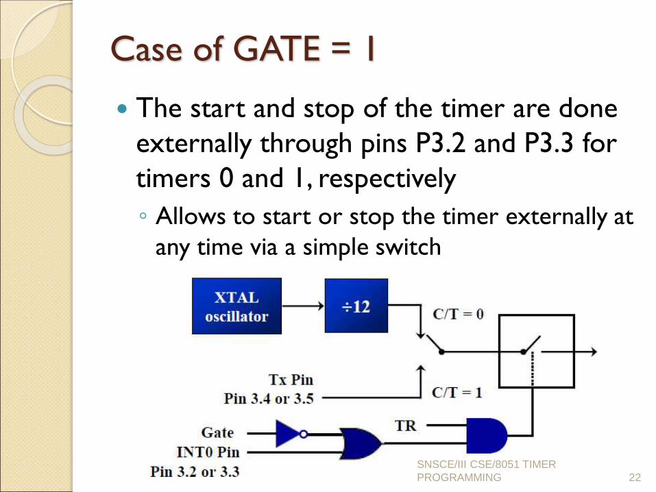
Case of GATE = 1
The start and stop of the timer are done
externally through pins P3.2 and P3.3 for
timers 0 and 1, respectively
◦ Allows to start or stop the timer externally at
any time via a simple switch
22
SNSCE/III CSE/8051 TIMER
PROGRAMMING


