3,350+ OPEN ACCESS BOOKS 108,000+ INTERNATIONAL AUTHORS AND EDITORS 115+ MILLION DOWNLOADS BOOKS DELIVERED TO 151 COUNTRIES AUTHORS AMONG TOP 1% MOST CITED SCIENTIST 12.2% AUTHORS AND EDITORS FROM TOP 500 UNIVERSITIES Selection of our books indexed in the Book Citation Index in Web of Science™ Core Collection (BKCI) Chapter from the book Electromotive Force and Measurement in Several Systems Downloaded from: http://www.intechopen.com/books/electromotive-force-and- measurement-in-several-systems PUBLISHED BY World's largest Science, Technology & Medicine Open Access book publisher Interested in publishing with IntechOpen? Contact us at [email protected]
Transcript
3,350+OPEN ACCESS BOOKS
108,000+INTERNATIONAL
AUTHORS AND EDITORS115+ MILLION
DOWNLOADS
BOOKSDELIVERED TO
151 COUNTRIES
AUTHORS AMONG
TOP 1%MOST CITED SCIENTIST
12.2%AUTHORS AND EDITORS
FROM TOP 500 UNIVERSITIES
Selection of our books indexed in theBook Citation Index in Web of Science™
Core Collection (BKCI)
Chapter from the book Electromotive Force and Measurement in Several SystemsDownloaded from: http://www.intechopen.com/books/electromotive-force-and-measurement-in-several-systems
PUBLISHED BY
World's largest Science,Technology & Medicine
Open Access book publisher
Interested in publishing with IntechOpen?Contact us at [email protected]
Eduard Montgomery Meira Costa Universidade Federal do Vale do São Francisco
Juazeiro, BA Brazil
1. Introduction
In all analysis of resonance at RLC circuits, the concept of equality in the inductive reactance and capacitive reactance generates the maximum energy transfer. In the same way, this concept is applied to transformers, due to parasitic capacitances present inter turns (Costa, 2009). Such concept determines explanation of several phenomena of the induced EMF on coils, showing through differential equations and others formalisms of how happens this phenomenon (Costa, 2009a). However, phenomena as secondary energy at Tesla Transformer (that is a pulse transformer (Lord, 1971), where the input energy is a square wave) present some problems that are not fully comprehensible, as the high energy in secondary coil apparently greater then input energy, which was explained in (Costa, 2009b; Costa, 2010) as the sum of responses of the induced EMF at secondary coil. By other side, when analysing these same transformers with input energy as sinusoidal excitation, the induced EMF at resonance appears in the same way, but with smaller gain. Considering planar coils, several researches are found, applied to microcircuits (Kaware et al, 1984; Conway, 2008; Anioin et al, 2008; Oshiro, 1987), as well in planar transformers (Oshiro et al, 1989). By other side, several analysis of coils, considering planar coils and ring coils, forming special transformers has been analysed, exciting one (primary) and verifying the other (secondary), in a experimental way, to find new expectations in this area. When exciting primary coil in these transformers, built with planar coil versus ring coil,
called direct system (having the planar coil or the ring coil as primary, and the other as the
secondary) or planar coil versus ring coil (called inverted system), the effect of induced EMF
at secondary coil presents some common characteristic previously yields studied in circuit
theory (as resonance due the RLC characteristic of the transformer). However, with the
experimental analysis of the induced EMF in these transformers, when exciting primary coil
with square wave and sinusoidal wave, although are found resonance frequencies at
frequencies (above 3 MHz) depending of the configuration (number of turns in each coil,
and type of coil – planar or ring), gain variations are seen. Also, on resonance frequencies,
other phenomena are seen, as high voltage gain in the transformer, even if the primary coil
of the transformer presents less turns than the secondary, which contradicts ideal
transformer theory.
These cases are analysed here, showing these phenomena, and checking the problem in some mathematical and experimental analysis. The induced EMF from primary coil to secondary coil at transformers in the resonance has shown several properties that generates
www.intechopen.com
Electromotive Force and Measurement in Several Systems
154
new perspectives in electromagnetic theory, as formalisms to develop new type of transformers, others explanations about resonance theory, analysis of energy transfer through resonance on coils, generation of high energy from low power sources, analysis about parasitic capacitances and others characteristics at coils and transformers, and others. This chapter treats of this problem, checking some experimental results, and mathematical formalisms that explain some properties and phenomena that occurs at secondary coil when the resonance frequency is reached in the coupled circuit (transformer), due to induced EMF generated by the excitation of the primary coil with square wave or sinusoidal wave.
2. Experimental methodology and data analysis of Induced EMF at coils
Several experiments were realized in special transformers built in planar coils versus ring coils, to found interesting results about resonance. In all cases, an excitation of square and sinusoidal alternating current were put as entry in primary transformers directly of the wave generator output, to verify the response at secondary coils of the transformers. The analysis of the results shown phenomena at resonance which are analysed here, showing high gains not expected in circuit theory.
2.1 Experimental methodology In present work were utilized some coils to prepare the transformers where the experiments were realized. These coils are built in copper wire with diameter d = 2.02 x 10⁻⁴ m (32 AWG) or d = 1.80 x 10⁻⁴ m (36 AWG). Were built several planar coils with diameter of D = 4.01 x 10⁻² m, with turn numbers of 20, 50, 200, 500 and 1600, and the ring coils with diameter of D = 4.65 x 10⁻² m, with turn numbers of 2, 5, 7, 9, 10, 12, 15, 20, 30 and 50. All coils were built so that their height are h = 1.8 x 10⁻⁴ m (case of 20 and 50 turns) and h = 5 x 10⁻⁴ m. In this way, the transformers present a planar coil inner ring coil, always based on crossing of the described coils, where this configuration is shown in Fig. 1.
Fig. 1. Basic layer of the studied transformer: Planar coil inner Ring coil.
The measurement of the capacitance between two coils (planar vs ring) presented the value of Cpr = 3.1 x 10⁻¹¹ F. The used equipments were: a digital storage oscilloscope Agilent Technologies DSO3202A with passive probe N2862A (input resistance = 10 MΩ and input capacitance ≃12pF), a function generator Rigol DG2021A and a digital multimeter Agilent Technologies U1252A. Initially, the experiments were realized exciting primary (being the planar coil) with a square wave of 5 Vpp (2.5 Vmax), and frequencies ranging from 1 kHz and 25 MHz, and observing the responses of the secondary open circuit (being the ring coil). Also, with this
www.intechopen.com
Resonance Analysis of Induced EMF on Coils
155
same waveform of excitation, the system was inverted, considering ring coil as primary (input of square wave) and planar coil as secondary (output analyzed). A posteriori, the excitation was changed by a sinusoidal waveform with the same amplitude, realizing the extraction of the data in direct system and inverted system. Considering the effects of parasitic capacitances (Cgi the parasitic capacitances in relation to a ground, and Cci turn to turn parasitic capacitances, i = 1,2), self (Li, i = 1,2) and mutual (M) inductances and resistances (ri, i = 1,2) of coils, the system can be analyzed as equivalent circuit shown in Fig. 2.
Fig. 2. Equivalent circuit to analysis of the system.
Inductances and mutual inductances of the coils (Hurley and Duffy, 1997; Su, Liu and Hui, 2009) are calculated using procedure presented in (Babic and Akyel, 2000; Babic et al., 2002; Babic and Akyel, 2006; Babic and Akyel, 2008), where some of obtained magnitudes of self inductances are shown in Table 1 as follows:
Turn number Self inductance (H)
10 4.33 x 10⁻⁷
20 1.85 x 10⁻⁶
30 4.07 x 10⁻⁶
50 1.10 x 10⁻⁵
200 1.67 x 10⁻⁴
500 9.48 x 10⁻⁴
1600 1.07 x 10⁻²
Table 1. Computed self inductances for planar coils.
The experimental data obtained with this configuration, a priori, were sufficient to determine several effects not common in literature, especially in relation to resonance described as the sum of system responses (when the input is a square waveform), as the high gain that contradicts theory of ideal transformers (in both waveform excitations).
2.1.1 Data analysis for excitation with square wave on direct system When the primary of the transformer was excited with square wave, the response of the system presented as a second order system, presenting a sinusoidal response with exponential dumping (Costa, 2009d). In this case, considering excitation of the planar coil (as the primary of the transformer), response at secondary is seen in the oscilloscope in time
division of 100 s/div we observe that the system response is verified in accordance with
Faraday’s law emf = -d/dt. This result may be seen in Fig. 3, where the signal of the output is
www.intechopen.com
Electromotive Force and Measurement in Several Systems
156
inverted to simplify the observations. In this case, this response is referred to a 200 turns planar coil as primary and a 10 turns ring coil as secondary in input square wave frequency f = 1 kHz. However, when inceasing time division of the oscilloscope for 500 ns/div, in this specific case of the system which generates the response seen in Fig. 3(a), the effects of parasitic capacitances may be observed as attenuated sine wave, as shown in Fig. 3(b). In this case we observe a double sinusoidal (modulated response) with exponential drop. This case is formally observed as effect of the values of the system transfer function, that can be observed only 15 < np/nr <25, being np is the turn number planar coil and nr is the turn number ring coil (Costa, 2009; Costa, 2009a).
(a) (b)
Fig. 3. (a) Oscilloscope image of input (upper) and output (lower) of the analyzed system
with time division 100 s/div, (b) System response with increasing oscilloscope time division.
When we observe the system responses in other configurations, is observed that the increase
of turns in planar coil reduces the lower frequency (that modulates the higher frequency or
the main response shown in Fig. 3(b)), as we can see in Fig. 4.
In Fig. 4, we observe that the system response follows equally the rise and the fall of the
square wave. Because these effects, when increasing the frequency of square wave applied
on primary of the system, we observe that the total system response is presented as the sum
of these responses separately. Clearly, the accumulated energy on system (in inductances
and parasitic capacitances) is added with the new response when the excitation rises or falls.
It is shown in Fig. 5(a), as simulation for 3 attenuated sine wave responses, and at Fig. 5(b) is
shown the same effect based on experimental results.
In the case of Fig. 6, we observe that the results have a DC component in response for each rise and fall of the square wave, which is observed in Fig. 7. Consequently this sum of responses is presented as:
0
( 1) ( sin exp( ( )) )n
po
p
v t p b t p a
(1)
where is a constant referring to peak response of the sine wave, a is a constant referring to DC level in response, b is a constant referring to exponential attenuation and p is the time
www.intechopen.com
Resonance Analysis of Induced EMF on Coils
157
when occur each change in the square wave, as we can see in (Costa, 2009c; Costa, 2010a) for some aspects of resonance on coils.
Fig. 4. Responses of the system excited with square wave of f = 1kHz in configurations: (a) 20 turns planar coil vs 9 turns ring coil; (b) 50 turns planar coil vs 12 turns ring coil; (c) 500 turns planar coil vs 7 turns ring coil and (d) 1600 turns planar coil vs 5 turns ring coil.
Fig. 5. (a) Simulation showing the sum of attenuated sine wave responses in some rises and falls of the applied square wave on system. (b) Response of the system defined with 200 turns planar coil and 12 turns ring coil, where we observe the sum of individual responses for each rise and fall of the square wave.
www.intechopen.com
Electromotive Force and Measurement in Several Systems
158
Due to the sum of responses, we find that when the responses is in phase with the square wave, i.e., the relation fr = fs/n, we find a maximum value in output, which refers to the sum of the sine waves in phase and their DC components. In this relation, fr is the frequency of the main sine wave of the response in each rise and fall of the square wave, fs the frequency of the square wave and n an integer. Thus, this sum refers to sum of total accumulated energy on coils. However, the resonance only occurs in specific frequencies, when the output is a perfect sine wave. In this case, we can see that effect of resonance is verified when the maximum energy peak is found. This occur in the frequency fr = fs, which may have values of voltage greater than peak to peak input voltage of the square wave, although the turn ratio of the transformer is lower than 1. This result may be observed in Fig. 5(a), when the responses are added sequentially, i.e.,
when t , with fr = fs. In this case, the maximum value of the peak to peak voltage on output is
max
0
(4 1)2 exp ( 1)
4
ki
ppi
T iV b a
(2)
where k is the number of cycles of the attenuated sine wave as system response to an input
step voltage and T is the period of this sine wave (oscillatory response). Based on this
example, we note in all experiments that the found problem due to induced EMF at
resonance is that the output is the sum of the responses in each rise and fall of the square
wave step voltage. Consequently, it is a result obtained that explains the high voltage of
Tesla transformer. These results are shown in Fig. 6, for some configurations of the analyzed
system.
In Fig. 6, the obtained data for these configurations are shown in Table 2. In accordance with these data, we observe that the system response excited with square
wave does not follow the common gain of the circuit theory, defined as turn ratio. In other
words, in usual circuit theory, the turn ratio determines voltage reduction, but in resonance
when is applied square wave as input signal, the response is sinusoidal presenting a visible
inversion (high gain defining increased voltage). Thus, for the same data shown in Table 2,
data in Table 3 shows the gain of the system in resonance and the expected output value in
accordance to circuit theory.
Turn number Planar (np)/Ring (nr)
Turn Ratio nr/np
vpp,max (V) f (kHz)
20/12 0.6 52.4 8130
50/7 0.14 8.0 13900
200/20 0.1 7.84 4050
500/5 0.01 1.17 18350
1600/30 0.01875 2.02 1570
Table 2. Data of the System Configurations shown in Fig. 8.
www.intechopen.com
Resonance Analysis of Induced EMF on Coils
159
Fig. 6. Resonance of the systems in configurations: (a) 20 turns planar coil vs 12 turns ring coil on f = 8130 kHz; (b) 50 turns planar coil vs 7 turns ring coil on f = 13900 kHz; (c) 200 turns planar coil vs 20 turns ring coil on f = 4050 kHz; (d) 500 turns planar coil vs 5 turns ring coil on f = 18350 kHz and (e) 1600 turns planar coil vs 30 turns ring coil on f = 1570 kHz.
Turn number Planar/Ring
vpp,max (V) v0/vi vpp - expected value of
circuit theory (V)
20/12 52.4 10.48 3.0
50/7 8.0 1.6 0.7
200/20 7.84 1.568 0.5
500/5 1.17 0.234 0.05
1600/30 2.02 0.404 0.09375
Table 3. Ratio Output/Input and Expected output for Data at Table 2.
www.intechopen.com
Electromotive Force and Measurement in Several Systems
160
These effects are clearly visible when using Equations (1) and (2), which show why the system at resonance can get high energy. The same effect is observed for the inverted system, i.e., when ring coil is the primary of the transformer and the planar coil is the secondary. This case is presented in the next section.
2.1.2 Data analysis for excitation with square wave with inverted system Considering the inversion of the system, i.e., ring coil as primary and planar coil as secondary, the response appears similarly to initial configuration. But due to the inversion of the values (parasitic capacitances, self inductances and resistances in the equivalent system shown in Fig. 2, and consequently changes in value of mutual inductance (Babic and Akyel, 2000; Babic et al., 2002; Babic and Akyel, 2006; Babic and Akyel, 2008) changes in transfer function are made, such that the output presents features similar to the cases where np/nr >25. In these cases, the inversion of the values in transfer function also generates a lower frequency on oscillatory response. Consequently, the system response presents resonance in lower frequencies than the initial configuration, as we see in (Costa, 2009d). Observing Fig. 7, we see the system responses for some configurations when the input
signal is a low frequency square wave (similarly to input step voltage). In this figure, we
clearly observe that the frequencies are lower than frequencies of system response in initial
configuration. Also, we observe that the input square wave is presented with effects of RL
circuit, due to passive probe of oscilloscope be in parallel to primary coil (Babic and Akyel,
2000; Babic et al., 2002; Babic and Akyel, 2006; Babic and Akyel, 2008).
When the frequency is increased, the same effect of sum of responses to each rise and fall of
the square wave defined in Equation (1) is observed, as shown in Fig. 8. In the same way,
when the relation fr = fs/n is verified, the output voltage reaches the maximum value,
although this response is not a perfect sine wave.
However, in accordance to Equations (1) and (2), when the relation fr = fs is verified, the
resonance occurs, and the output reaches the maximum value with a perfect sine wave.
Since that the frequencies of the responses are lower, the resonance occurs in low
frequencies of the square wave, in comparison with the initial configuration. Some results of
this case are shown in Fig. 9.
We observe in this case, that the output voltage (vpp) is greater than the initial configuration.
Clearly, this effect is observed because two components are considered: the turn ratio (effect of
the transformer, as circuit theory) and the sum of the sinusoidal responses as (1).
Consequently, the resonance output voltage is greater than the effect of the transformer alone.
For configurations shown in Fig. 7, 8 and 9, the maximum values of the output voltage are
shown in Table 4, with their respective turn ratio and resonance frequency.
However, although in this case occurs an effect of the turn ratio (transformer), in accordance to results shown in Table 4, this effect defines that this is not always right, as in the case of the configurations of 2 turns ring coil vs 1600 turns planar coil, 2 turns ring coil vs 50 turns planar coil, 5 turns ring coil vs 500 turns planar coil and others with turn ratio greater than 100. It is due to impedance of the circuit, which eliminates various sinusoidal components of the input square wave, reducing total value on output. In the realized measurements with all coils in the initial configuration and inverted system, we can see the behavior of the output voltage when varying turn number of the coils (ring and planar) in Fig. 10, for input square wave of 5 V peak to peak. With this Fig. 10 we can generate a direct comparison for both cases worked, verifying the gain.
www.intechopen.com
Resonance Analysis of Induced EMF on Coils
161
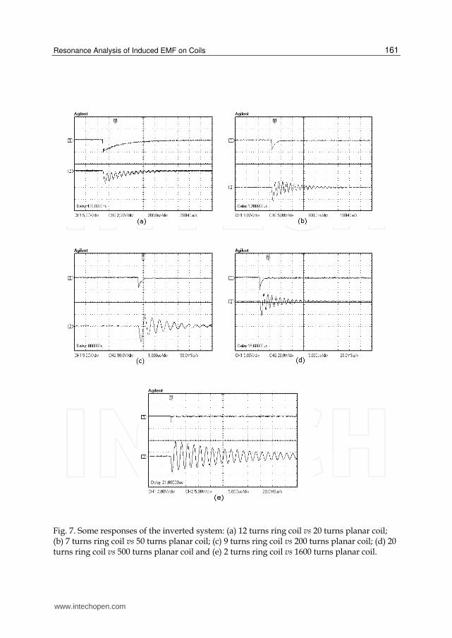
Fig. 7. Some responses of the inverted system: (a) 12 turns ring coil vs 20 turns planar coil; (b) 7 turns ring coil vs 50 turns planar coil; (c) 9 turns ring coil vs 200 turns planar coil; (d) 20 turns ring coil vs 500 turns planar coil and (e) 2 turns ring coil vs 1600 turns planar coil.
www.intechopen.com
Electromotive Force and Measurement in Several Systems
162
Fig. 8. Sum of responses on inverted system in configurations: (a) 15 turns ring coil vs 20 turns planar coil; (b) 2 turns ring coil vs 50 turns planar coil; (c) 20 turns ring coil vs 200 turns planar coil; (d) 10 turns ring coil vs 500 turns planar coil and (e) 7 turns ring coil vs 1600 turns planar coil.
www.intechopen.com
Resonance Analysis of Induced EMF on Coils
163
Fig. 9. Resonance in some inverted systems: (a) 7 turns ring coil vs 20 turns planar coil; (b) 15 turns ring coil vs 50 turns planar coil; (c) 12 turns ring coil vs 200 turns planar coil; (d) 5 turns ring coil vs 500 turns planar coil and (e) 30 turns ring coil vs 1600 turns planar coil.
In case of the initial configuration (direct system), the gain obtained is increased follows in accordance to turn numbers of the both coils. In the case of the inverted system, the gain is decreasing to turn number ring coil, and reaches the maximum peak voltage in configurations defined as low turn number in ring coil and high turn number in planar coil (in the obtained experimental results this value is 5 turn number ring coil). The obtained values for turn number in ring coil lower than 5 is decreasing, when it is crossed with turn number higher than 200 in planar coils. Naturally, this effect is verified as being the variation of the values of parasitic capacitances, self-inductances and mutual inductance (Babic and Akyel, 2000; Babic et al., 2002; Babic and Akyel, 2006; Babic and Akyel, 2008), since that these planar coils are built in more than one layer in the same disk diameter.
www.intechopen.com
Electromotive Force and Measurement in Several Systems
164
Turn number Ring (nr)/ Planar (np)
Turn Ratio np/nr
vpp,max (V) f (kHz)
12/20 1.667 21.4 13900
7/50 7.143 96 5920
9/200 22.222 170 1573
20/500 25.0 328 560
2/1600 800.0 322 402
15/20 1.333 17.6 13900
2/50 25.0 99.2 5700
20/200 10.0 174 1580
10/500 50.0 336 540
7/1600 228.571 400 407
7/20 2.857 38.8 14000
15/50 3.333 72.8 5770
12/200 16.667 166 1520
5/500 100.0 362 530
30/1600 53.333 342 442
Table 4. Results to Inverted System in Configurations of Fig. 7, 8 and 9.
Also, other effect observed in inverted system is the output peak voltage for low turn number in ring coil. When the turn number in planar coil is increased, considering 5 turn number in ring coil, the graph seen in Fig. 10(b) increases quickly, showing a better relationship to maximum response in resonance. Because this relationship between coils, higher sinusoidal voltage is obtained, showing important results between self inductances and others parameters evaluated on system to generate high voltages on air-cored transformers, as well how we can built small pulse transformers [28] with high voltage output based on planar coil inner ring coil and others applications for energy transfer.
(a) (b)
Fig. 10. Output variations according to turn number coils: (a) Initial configuration; (b) Inverted System.
www.intechopen.com
Resonance Analysis of Induced EMF on Coils
165
Finally, we observe that these results, in both cases (initial configuration or direct system, and inverted system) show important effects on resonance in pulsed systems, when they involve coils, which may be used to analysis on electromagnetic interference and other problems of power electronics, pulse transformer and computational systems.
2.1.3 Data analysis for excitation with sine wave in direct system and comparison with square wave excitation When analysing the response of the system when excitation is a sinusoidal waveform, the result presented is a sinusoidal wave with phase variation. But, when the resonance is reached, high gain is noted, however slightly larger than the response of the excitation with square wave. In both cases, the induced EMF at resonance generates the phenomenon of that the coupled circuit theory (transformer) and circuit theory is not satisfied, since that the high gain do not satisfies the ideal gain of the transformers. Considering direct system, the response at low frequencies (from 1 kHz to 20 ~ 50 kHz) are generally noise, as shown in Fig. 11. It is due to effect of inductances, mutual inductances, and parasitic capacitances, which determines a filter which cut these frequencies. For frequencies above 50 kHz, response of the system appears as lagged sine wave, as we can see in Fig. 12.
Fig. 11. (a) 10 turns planar coils versus 15 turns ring coil at 30 kHz; (b) 20 turns planar coils versus 30 turns ring coil at 40 kHz; (c) 30 turns planar coils versus 10 turns ring coil at 5 kHz; (d) 200 turns planar coils versus 10 turns ring coil at 50 kHz;
www.intechopen.com
Electromotive Force and Measurement in Several Systems
166
Fig. 12. (a) 20 turns planar coils versus 10 turns ring coil at 200 kHz; (b) 30 turns planar coils versus 15 turns ring coil at 1000 kHz; (c) 50 turns planar coils versus 50 turns ring coil at 3500 kHz; (d) 200 turns planar coils versus 30 turns ring coil at 2850 kHz.
Analysing the problem of these frequencies, we can see that the response of the system is:
sinov A t (3)
where A() is the amplitude and () is the phase, which both depends upon frequency.
Amplitude varies with inductances, mutual inductances, resistances and parasitic
capacitances of the system, presenting similar graph as system excited with square wave,
but with fewer resonance peaks, as view in Fig. 13, which compares output of the system in
some cases excited by sine waves and square waves. The number of resonance peaks in
output of the system when escited by square waves is due to components of the Fourier
series that passes at filter, generating several resonance peaks with increased amplitudes, as
frequency increases,which similarly we find in (Cheng, 2006, Huang et al, 2007) analysis of
problems involving harmonic analysis.
In the case of sine wave excitation, resonance responses are found as higher output as
excitation with square waves. When considering the sinusoidal excitation, the maximum
gain are presented at Table 5, where are seen the gains of some experimented systems,
considering ring coil as primary, and in Table 6 are seen obtained ratio of these two gains for
www.intechopen.com
Resonance Analysis of Induced EMF on Coils
167
direct system (ring coil as primary), where are seen that in resonance with sine wave
excitation, the gain is higher than square wave excitation.
Fig. 13. Graphs of voltage versus frequency of the system built in 20 turns planar coil versus ring coil excited by: (a) sine wave; (b) square wave; and system built in 500 turns planar coil versus 12 turns ring coil excited by (c) sine wave; (d) square wave.
Coil 10 20 50 200 500
10 0.14 3.80 12.40 28.40 50.00
12 0. 46 1.84 13.36 13.04 50.80
20 0.22 1.26 11.88 22.80 51.60
30 0.10 1.47 6.12 19.20 5.04
50 1.98 2.20 6.04 5.04 0.16
Table 5. Gains of transformers with sinusoidal excitation (direct system): columns with planar coil; rows with ring coil.
www.intechopen.com
Electromotive Force and Measurement in Several Systems
168
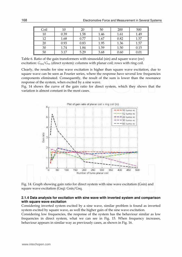
Coil 10 20 50 200 500
10 0.39 1.58 1.46 1.61 1.49
12 1.68 0.77 1.67 0.82 1.57
20 0.93 0.83 1.95 1.36 1.57
30 1.74 1.84 1.59 1.50 0.15
50 3.17 5.29 3.68 0.60 0.01
Table 6. Ratio of the gain transformers with sinusoidal (sin) and square wave (sw) excitation: Gsin/Gsw (direct system): columns with planar coil; rows with ring coil.
Clearly, the results for sine wave excitation is higher than square wave excitation, due to square wave can be seen as Fourier series, where the response have several low frequencies components eliminated. Consequently, the result of the sum is lower than the resonance response of the system, when excited by a sine wave. Fig. 14 shows the curve of the gain ratio for direct system, which they shows that the variation is almost constant in the most cases.
Fig. 14. Graph showing gain ratio for direct system with sine wave excitation (Gsin) and square wave excitation (Gsq): Gsin/Gsq.
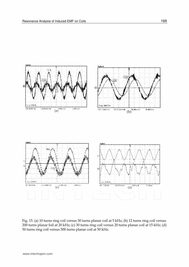
2.1.4 Data analysis for excitation with sine wave with inverted system and comparison with square wave excitation Considering inverted system excited by a sine wave, similar problem is found as inverted system excited by square wave, as well the higher gain of the sine wave excitation. Considering low frequencies, the response of the system has the behaviour similar as low frequencies in direct system, what we can see in Fig. 15. When frequency increases, behaviour appears in similar way as previously cases, as shown in Fig. 16.
www.intechopen.com
Resonance Analysis of Induced EMF on Coils
169
Fig. 15. (a) 10 turns ring coil versus 30 turns planar coil at 5 kHz; (b) 12 turns ring coil versus 200 turns planar foil at 20 kHz; (c) 30 turns ring coil versus 20 turns planar coil at 15 kHz; (d) 50 turns ring coil versus 500 turns planar coil at 50 kHz.
www.intechopen.com
Electromotive Force and Measurement in Several Systems
170
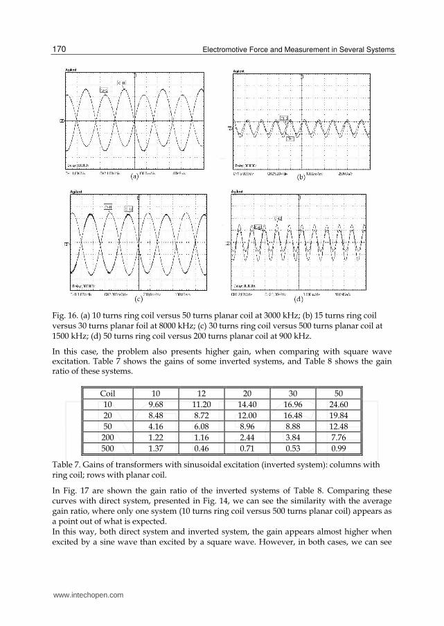
Fig. 16. (a) 10 turns ring coil versus 50 turns planar coil at 3000 kHz; (b) 15 turns ring coil versus 30 turns planar foil at 8000 kHz; (c) 30 turns ring coil versus 500 turns planar coil at 1500 kHz; (d) 50 turns ring coil versus 200 turns planar coil at 900 kHz.
In this case, the problem also presents higher gain, when comparing with square wave excitation. Table 7 shows the gains of some inverted systems, and Table 8 shows the gain ratio of these systems.
Coil 10 12 20 30 50
10 9.68 11.20 14.40 16.96 24.60
20 8.48 8.72 12.00 16.48 19.84
50 4.16 6.08 8.96 8.88 12.48
200 1.22 1.16 2.44 3.84 7.76
500 1.37 0.46 0.71 0.53 0.99
Table 7. Gains of transformers with sinusoidal excitation (inverted system): columns with ring coil; rows with planar coil.
In Fig. 17 are shown the gain ratio of the inverted systems of Table 8. Comparing these curves with direct system, presented in Fig. 14, we can see the similarity with the average gain ratio, where only one system (10 turns ring coil versus 500 turns planar coil) appears as a point out of what is expected. In this way, both direct system and inverted system, the gain appears almost higher when excited by a sine wave than excited by a square wave. However, in both cases, we can see
www.intechopen.com
Resonance Analysis of Induced EMF on Coils
171
that considering turn ratio (that is, ideal gain transformer) at resonance, the gain does not satisfy coupled circuit theory. This effect of EMF in secondary transformers when resonance is reached is interesting phenomenon that shows new perspectives for this area. Due to these analyses, several researches can be realized from resonance, applying this special transformer and obtained data and results to new technologies. In this way, researches about induced EMF in cascaded direct systems and inverted systems to reach high output voltages and others are optimal perspectives, as well their applications.
Coil 10 12 20 30 50
10 1.68 1.75 1.76 1.66 1.81
20 1.93 1.73 1.67 1.87 1.94
50 2.42 2.30 1.60 1.21 1.04
200 1.60 1.26 3.18 1.60 1.67
500 43.85 3.87 1.68 0.75 0.58
Table 8. Ratio of the gain transformers with sinusoidal (sin) and square wave (sw) excitation: Gsin/Gsw (inverted system): columns with ring coil; rows with planar coil.
Fig. 17. Graph showing gain ratio for inverted system with sine wave excitation (Gsin) and square wave excitation (Gsq): Gsin/Gsq.
3. Conclusion
This work shows very important results about the induced EMF in coupled circuits (transformers), that not only explains phenomena as high voltage of Tesla transformer, as the found problem of not satisfaction of resonance in circuit theory due to high gain found in output of the special transformers analysed. Some analysis generate simple solutions to this problem, but this work open a new investigative problem in this area, that here is
www.intechopen.com
Electromotive Force and Measurement in Several Systems
172
proposed. This work was based on experimental results about air core special transformer, excited by square waves and sine waves in frequencies ranging from 1 kHz to 25 MHz. These transformers were built with planar coils inner ring coils, where initially planar coil was used as primary to verify the induced emf response in ring coil and, a posteriori, we invert primary and secondary, exciting ring coil with the square wave, to verify output on planar coil. In the analysis of the results of the system when excited by a square wave, were observed that the response of the system shows existence of parasitic capacitances, and the response to low frequencies are similar to response of step voltage excitation. But, with the increasing frequency, the responses in each rise and fall of the square wave are added, generating low voltages when this sum of responses are not in phase, and high voltage when the responses are in phase with the square wave, i.e., when is satisfied the relationship fr = fs/n (fr sinusoidal frequency of the response, fs square wave frequency and n number of cycles of the sinusoidal frequency of the response on semi cycle of the square wave), where this is because energy accumulation in each cycle by the coils in transformer. The higher voltage on output is obtained when the relation fr = fs is verified (or n = 1). In this case, the maximum values of voltages on output are sinusoidal, showing a resonant response of the system. In both cases (diretc system and inverted system), the response reaches values greater than input, although the turn ratio between coils does not meet the requirements of the circuit theory. So, we observe in results of the inverted system that, when the turn number of planar coil increases too, effects of inductances, parasitic capacitances and resistances generates an active filter on input, which reduces the output voltage. Finally, we see that the better transfer energy observed is obtained to inverted system when turn number ring coil is about 5, and turn number planar coil is great, shown as peak voltage in Fig. 10(b). When considering sine wave excitation, we note that the system, both direct and inverted sistems, presents higher gain than square wave excitation, that is with average 1.5 times. It is due to amplitude of the sine wave components of the square wave (considering Fourier series), that are lower than peak of the sine wave excitation. The system acts as an filter that eliminates some sine wave components of the square wave, and the response is almost always lower than effect of direct sine wave excitation. Due to results, possibilities of cascaded systems excited by sine wave can generate high resonance voltages, which is shown as new perspectives of application of the high alternating voltages, and others researches with these special transformers, as well induced EMF. Thus, in both cases, important results are shown, that may be used in researches of electromagnetic interference, computational systems, power electronics, pulse transformers and others excited by square waves and sine waves.
4. References
Anioin, B. A. et al., “Circuit Properties of Coils”. IEE Proc.-Sci. Mes. Technol., Vol 144, No. 5, pp. 234-239, September 1997.
Babic, S. I., and Akyel, C.,“Improvement in Calculation of the Self- and Mutual Inductance of Thin-Wall Solenoids and Disk Coils”, IEEE Transactions on Magnetics, Vol. 36, No. 4, pp. 1970-1975, July 2000.
Babic, S. I., and Akyel, C., and Kincic, S.,“New and Fast Procedures for Calculating the Mutual Inductance of Coaxial Circular Coils (Circular CoilDisk Coil)”, IEEE Transactions on Magnetics, Vol. 38, No. 5, pp. 2367-2369, September 2002.
www.intechopen.com
Resonance Analysis of Induced EMF on Coils
173
Babic, S. I., and Akyel, C., “New Analytic-Numerical Solutions for the Mutual Inductance of
Two Coaxial Circular Coils With Rectangular Cross Section in Air”, IEEE
Transactions on Magnetics, Vol. 42, No. 6, pp. 1661-1669, June 2006.
Babic, S. I., and Akyel, C.,“Calculating Mutual Inductance Between Circular Coils With
Inclined Axes in Air”, IEEE Transactions on Magnetics, Vol. 44, No. 7, pp. 1743-
1750, July 2008.
Cheng, K. W. E. et al., “Examination of Square-Wave Modulated Voltage Dip Restorer and
Its Harmonics Analysis”, IEEE Transactions on Energy Conversion, Vol. 21, No. 3,
pp. 759-766, September 2006.
Conway, J. T., “Noncoaxial Inductance Calculations without the Vector Potential for
Axissymmetric Coils and Planar Coils”, IEEE Transactions on Magnetics, Vol. 44,
No. 4, pp. 453-462, April 2008.
Costa, E.M.M. (2009). Parasitic Capacitances on Planar Coil. Journal of Electromagnetic Waves
and Applications. Vol. 23, pp. 2339-2350, 2009.
Costa, E.M.M. (2009a). A Basic Analysis About Induced EMF of Planar Coils to Ring Coils.
Progress in Electromagnetics Research B, Vol. 17, pp. 85-100, 2009.
Costa, E.M.M. (2009b). Resonance on Transformers Excited by Square Waves and Explanation of
the High Voltage on Tesla Transformers. Progress in Electromagnetics Research B, Vol.
18, pp. 205-224, 2009.
Costa, E.M.M. (2009c). Resonance Between Planar Coils Vs Ring Coils Excited by Sqare Waves.
Progress in Electromagnetics Research B, Vol. 18, pp. 59-81, 2009.
Costa, E.M.M. (2009d). Responses in Transformers Built Planar Coils Inner Ring Coils Excited by
Square Waves. Progress in Electromagnetics Research B, Vol. 18, pp. 43-58,
2009.
Costa, E.M.M. (2010). Resonance on Coils Excited by Square Waves: Explaining Tesla Transformer.
IEEE Transactions on Magnetics, Vol. 46, pp. 1186-1192, 2010.
Costa, E.M.M. (2010a). Planar Transformers Excited by Square Waves Progress in
Electromagnetics Research, Vol. 100, pp. 55-68, 2010.
Huang, Z., Cui, Y., and Xu, W., “Application of Modal Sensitivity for Power System
Harmonic Resonance Analysis”, IEEE Transactions on Power Systems, Vol. 22, No.
1, pp. 222-231, February 2007.
Hurley, W. G. and Duffy, M. C., “Calculation of Self- and Mutual Impedances in Planar
Sandwich Inductors”, IEEE Transactions on Magnetics, Vol. 33, No. 3, pp. 2282-
2290, May 1997.
Kaware, K., H. Kotama, and K. Shirae, “Planar Inductor”, IEEE Transactions on Magnetics,
Volume MAG-20, No.5, pp. 1984-1806, September 1984.
Lord, H.W. (1971). Pulse Transformers. IEEE Transactions on Magnetics, Vol. 7, pp. 17-28,
1971.
Oshiro, O., Tsujimoto, H., and Shirae, K., “A Novel Miniature Planar Inductor”, IEEE
Transactions on Magnetics, Volume MAG-23, No.5, pp. 3759-3761, September
1987.
Oshiro O., Tsujimoto, H., and Shirae, K., “Structures and Characteristics of Planar
Transformers”, IEEE Translation Journal on Magnetics in Japan, Vol. 4, No. 5, pp.
332-338, May, 1989.
www.intechopen.com
Electromotive Force and Measurement in Several Systems
174
Su, Y. P., Liu, X., and Hui, S. Y. R., “Mutual Inductance Calculation of Movable Planar Coils
on Parallel Surfaces”, IEEE Transactions on Power Electronics, Vol. 24, No. 4, pp.
1115-1124, April 2009.
www.intechopen.com
Electromotive Force and Measurement in Several SystemsEdited by Prof. Sadik Kara
ISBN 978-953-307-728-4Hard cover, 174 pagesPublisher InTechPublished online 21, November, 2011Published in print edition November, 2011
InTech ChinaUnit 405, Office Block, Hotel Equatorial Shanghai No.65, Yan An Road (West), Shanghai, 200040, China
Phone: +86-21-62489820 Fax: +86-21-62489821
This book is devoted to different sides of Electromotive Force theory and its applications in Engineeringscience and Industry. The covered topics include the Quantum Theory of Thermoelectric Power (SeebeckCoefficient), Electromotive forces in solar energy and photocatalysis (photo electromotive forces),Electromotive Force in Electrochemical Modification of Mudstone, The EMF method with solid-state electrolytein the thermodynamic investigation of ternary copper and silver chalcogenides, Electromotive ForceMeasurements and Thermodynamic Modelling of Electrolyte in Mixed Solvents, Application of ElectromotiveForce Measurement in Nuclear Systems Using Lead Alloys, Electromotive Force Measurements in High-Temperature Systems and finally, Resonance Analysis of Induced EMF on Coils.
How to referenceIn order to correctly reference this scholarly work, feel free to copy and paste the following:
Eduard Montgomery Meira Costa (2011). Resonance Analysis of Induced EMF on Coils, Electromotive Forceand Measurement in Several Systems, Prof. Sadik Kara (Ed.), ISBN: 978-953-307-728-4, InTech, Availablefrom: http://www.intechopen.com/books/electromotive-force-and-measurement-in-several-systems/resonance-analysis-of-induced-emf-on-coils