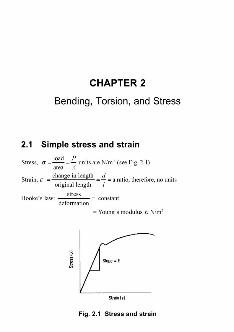
CHAPTER 2 Bending, Torsion, and Stress 2.1 Simple stress and strain Hooke’s law: = Y oung’s modulus EN/m 2 2 load Stress, uni ts are N/m (see Fig. 2.1) area change in length Strain, a ratio, theref ore, no units original length PA dlσ ε = = = = = Fig. 2.1 Stress and strain stress constant deformation =
Transcript
8/14/2019 8344x_02
http://slidepdf.com/reader/full/8344x02 1/18
8/14/2019 8344x_02
http://slidepdf.com/reader/full/8344x02 2/18
8/14/2019 8344x_02
http://slidepdf.com/reader/full/8344x02 3/18
8/14/2019 8344x_02
http://slidepdf.com/reader/full/8344x02 4/18
8/14/2019 8344x_02
http://slidepdf.com/reader/full/8344x02 5/18
8/14/2019 8344x_02
http://slidepdf.com/reader/full/8344x02 6/18
8/14/2019 8344x_02
http://slidepdf.com/reader/full/8344x02 7/18
Bending, Torsion, and Stress 53
For solid or hollow shafts of uniform cross-section, the torsion formula is(see Figs 2.6 and 2.7)
T = torque applied (Nm) J = polar second moment of area (m 4)τ = shear stress (N/m 2)
R = radius (m)G = modulus of rigidity (N/m 2)θ = angle of twist (rad)l = length (m)
Fig. 2.6 Torsion
T G = = J R l
τ θ
8/14/2019 8344x_02
http://slidepdf.com/reader/full/8344x02 8/18
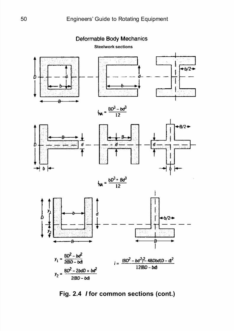
Engineers’ Guide to Rotating Equipment54
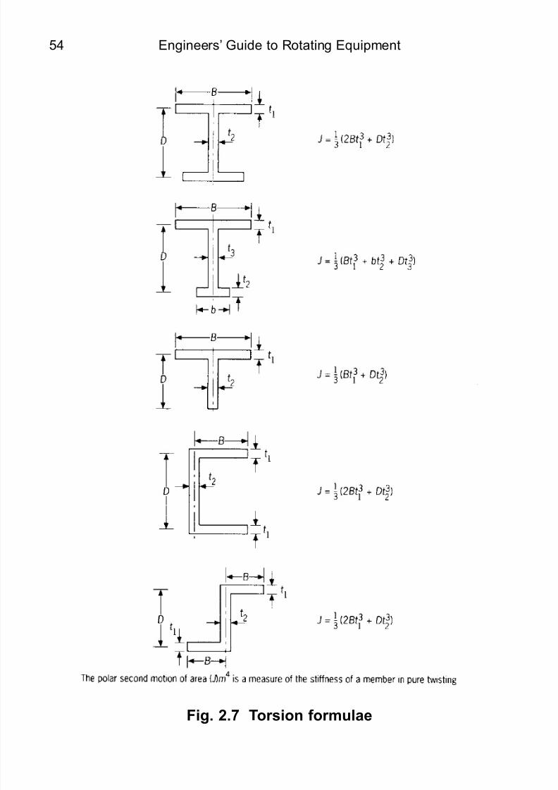
Fig. 2.7 Torsion formulae
8/14/2019 8344x_02
http://slidepdf.com/reader/full/8344x02 9/18
Bending, Torsion, and Stress 55
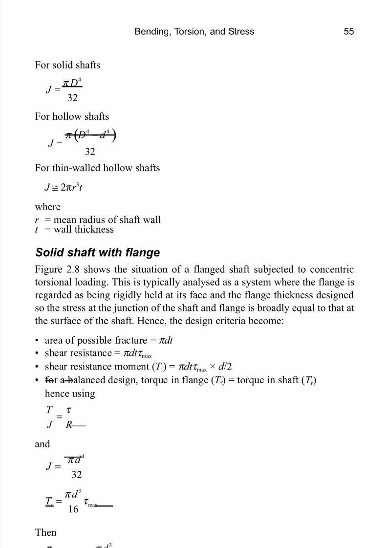
For solid shafts
For hollow shafts
For thin-walled hollow shafts
J ≅ 2πr 3
t wherer = mean radius of shaft wallt = wall thickness
Solid shaft with flangeFigure 2.8 shows the situation of a flanged shaft subjected to concentrictorsional loading. This is typically analysed as a system where the flange isregarded as being rigidly held at its face and the flange thickness designedso the stress at the junction of the shaft and flange is broadly equal to that atthe surface of the shaft. Hence, the design criteria become:
• area of possible fracture = π dt • shear resistance = π dt τ max
• shear resistance moment ( T f ) = π dt τ max × d /2
• for a balanced design, torque in flange ( T f ) = torque in shaft ( T r )hence using
and
Then
4
32
D J =
π
( )4 4
32
D d J =
π −
T J R
τ =
4
32
d J
π =
3
r max16d
T π
τ =
32
max max2 16d
d t π π
τ τ ≅
8/14/2019 8344x_02
http://slidepdf.com/reader/full/8344x02 10/18
Engineers’ Guide to Rotating Equipment56
Hence as a ‘rule of thumb’ for flange design; theoretical flange thickness≥ d /8. In practice (and in flange design codes), the flange thickness isincreased above this minimum value to allow for the weakening effect of flange bolt holes and the need for significant flange-to-flange bolting forces.
Strain energy (U) in torsionIn torsion, strain energy ( U ) is expressed as
Torsion of non-circular sectionsIf a section concentrically loaded in torsion is not of uniform circular shape,the stress distribution is not a simple case. Since projections cannot carry
any stress at their tips, a stress gradient must exist between each tip and theadjacent points of maximum stress. Stress is generally assumed to become amaximum at approximately the greatest distance from the centre at which acontinuous circular annulus can be formed within the section. The stressthen varies uniformly between its maximum value and zero at the axis, and
between its maximum value and zero at the projection extremities. The
2 2
2 2T l GJ
U GJ l
θ = =
D I A D
R
Fig. 2.8 Torsional loading of a flanged shaft
8/14/2019 8344x_02
http://slidepdf.com/reader/full/8344x02 11/18
Bending, Torsion, and Stress 57
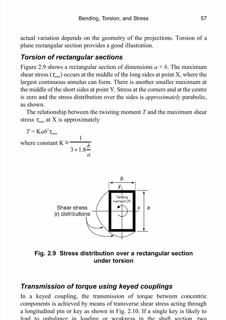
actual variation depends on the geometry of the projections. Torsion of a plane rectangular section provides a good illustration.
Torsion of rectangular sectionsFigure 2.9 shows a rectangular section of dimensions a × b . The maximumshear stress ( τ max) occurs at the middle of the long sides at point X, where thelargest continuous annulus can form. There is another smaller maximum atthe middle of the short sides at point Y . Stress at the corners and at the centreis zero and the stress distribution over the sides is approximately parabolic,as shown.
The relationship between the twisting moment T and the maximum shear stress τ max at X is approximately
T = K ab 2τ max
where constant K 1
3 1.8ba
≅
+
Transmission of torque using keyed couplingsIn a keyed coupling, the transmission of torque between concentriccomponents is achieved by means of transverse shear stress acting througha longitudinal pin or key as shown in Fig. 2.10. If a single key is likely tolead to unbalance in loading or weakness in the shaft section, twodiametrically opposed square keys of smaller size may be used. In certain
applications the key may be integral with the shaft, i.e. where stress intensity
Fig. 2.9 Stress distribution over a rectangular sectionunder torsion
8/14/2019 8344x_02
http://slidepdf.com/reader/full/8344x02 12/18
Engineers’ Guide to Rotating Equipment58
is exceptionally high or the components need to slide relative to each other.In this case the key is called a ‘spline’. The logical conclusion of this
concept is a splined shaft having a series of uniformly circumferentiallyspaced splines engaging with a corresponding female socket, as shown inFig. 2.11. Some broad ‘rules of thumb’ in key sizing are:
1. The maximum key width w may be taken as d /4 where d is the shaftdiameter.
2. The effective key length (l) may be approximated to 3 d /2 and the widthadjusted accordingly. With this proportion w≤d /4.
In either case the calculated key length should be increased to allow for therounded ends of the key (i.e. it will not provide full drive over its fulllength).
Effective keylength ( l )
Fig. 2.10 A square key end shape
8/14/2019 8344x_02
http://slidepdf.com/reader/full/8344x02 13/18
Bending, Torsion, and Stress 59
Single-key, loose-flange couplingsFigure 2.12 shows typical outline design dimensions for a single-keyedloose-flange coupling. Some typical design equations and crude rules of thumb are:
• boss diameter ( D) > 2 d to allow for the keyway
• torque resistance of the key ( T k ) when τ k = allowable shear stressin the key
• bolt shear resistancewheren = number of boltsδ = bolt diameter
• the pitch radius ( R) of the bolts and the bolt diameter ( δ ) are found by
simple trial and error in the above equation. Normally, for a solid shaft, a bolt diameter ( δ) of δ = d /6 is a good starting point. Another typicalguideline calculation is
bolt diameter ( δ ) =
DIAMETER(d)
Fig. 2.11 ‘Keyed’ drives on shafts (a) A circular key(b) A square key (c) A splined shaft
2
k 8ld
τ ≅
2 bolt( 1)
4n πδ τ −
≅
0.4238 mm
d n
+√
8/14/2019 8344x_02
http://slidepdf.com/reader/full/8344x02 14/18
Engineers’ Guide to Rotating Equipment60
2.5 Combined bending and torsionIn most practical rotating equipment applications, the effects of bending andtorsion do not exist in isolation, but are combined. The overall result is toincrease stress (and resulting fatigue) loadings, thereby increasing thenecessary factor of safety that has to be built in to the design if the
equipment is to perform satisfactorily.For a shaft of diameter, d , in combined bending and torsion the following
equations are used:
Maximum resultant shear stress
τ =√where
p = tensile or compressive stressq = shear stress acting on the same plane as p
Maximum safe shear stress
τ max =
D I A D
= 2 d
Fig. 2.12 Single-keyed loose-flange coupling: typicalarrangement and dimensions
22
4 p
q +
E3
16T d π
8/14/2019 8344x_02
http://slidepdf.com/reader/full/8344x02 15/18
Bending, Torsion, and Stress 61
whereT E = √(M 2 + T 2) termed the ‘equivalent torque’ resulting from bending and
moment, M , and torque, T .Figure 2.13 shows a typical application of equivalent torque, T E, criterion for a diesel engine crankshaft – a classic example of a combined bendingand torsion loading system. The figure also shows approximate designdimensions in terms of the main journal diameter, D .
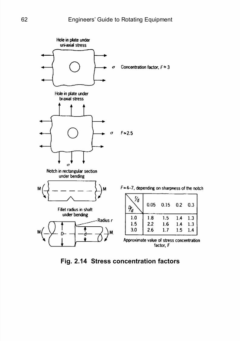
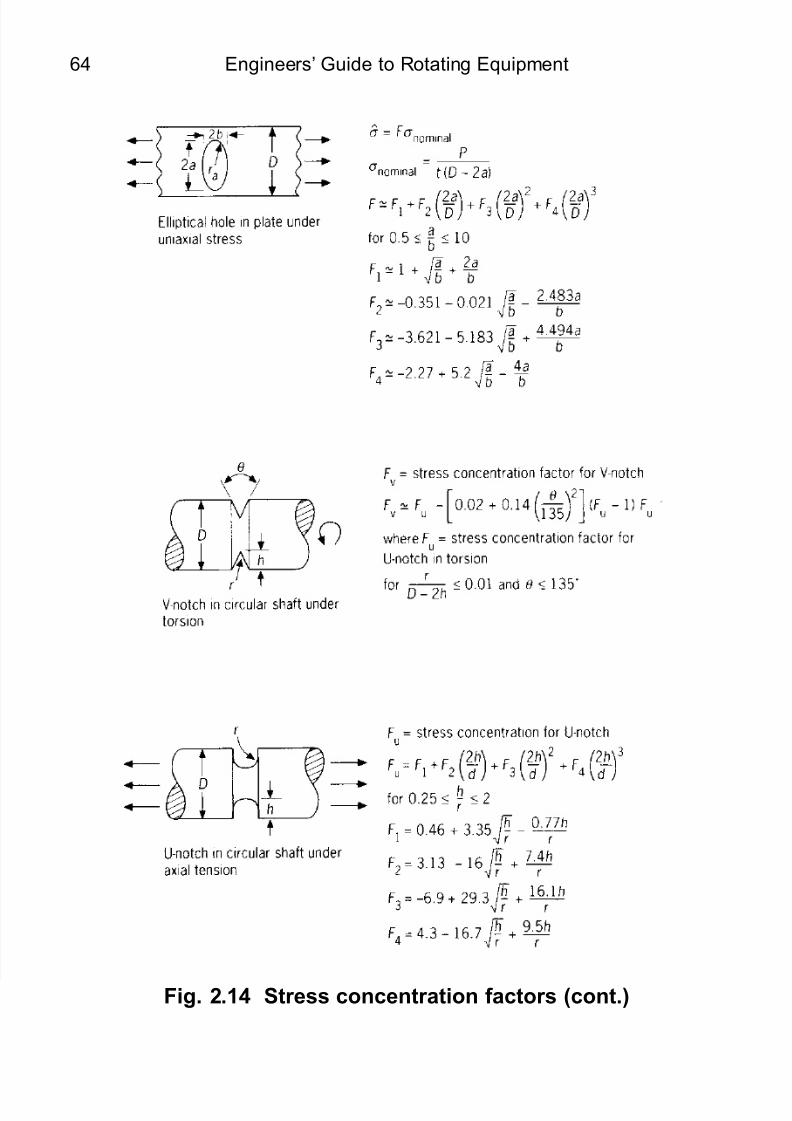
2.6 Stress concentration factors
The effective stress in a component can be raised well above its expectedlevels owing to the existence of geometrical features causing stressconcentrations under dynamic elastic conditions. Typical design stressconcentration factors are as shown in Fig. 2.14.
For the overhung crankshaft: Equivalent torque (T E) ≅P√(L2 + R 2)
Fig. 2.13 Crankshaft: some torque design ‘rules of thumb’