56
HVF & HVG Type
| Date post: | 29-Nov-2015 |
| Category: |
Documents |
| Upload: | edmundo-zura |
| View: | 342 times |
| Download: | 5 times |

HVF & HVG Type

We build a better future!
HVG Type
HVF Type

Compact structure to minimize the switchgear dimension- Wide 600mm switchgear available with small size & light weight- Mechanical endurance of 20,000 operations- 7.2kV, 8-25kA, 400-1,250A
HVG
Retaining the high dielectric strength with the interrupter of the high vacuum degree of 10-7mbar.
Providing reliable mechanical performance and long-life expectancy with rigid structure of motor-spring energy stored mechanism.
Having excellent breaking capability with the special contact material designed by the advanced vacuum technology.
Having rapid breaking time of 3 cycle.
Certified by New IEC publication 62271-100 and other related standards by HYUNDAI in ISO9001/14001 and OHSAS18001 certified facilities.
Features 4
Ratings 6
Type of Mounting 11
Technical Data 12
Arc Quenching System 13
Service Life 14
Power Consumption & Rated Current 15
Standard Accessories 16
Additional Options 17
Control Circuits 19
Dimensions 22
Order Information 52
Ensuring excellent switching capability and high quality with various advantages
HVF
Rigid structure to prove high reliability and long-life expectancy- Wide 600 / 800mm switchgear available with small size & light weight- Mechanical endurance of 30,000 operations
- (IEC) 7.2-17.5kV 25-50kA 630-4,000A 24/25.8kV 12.5-31.5kA 630-3,150A 36/40.5kV 25-31.5kA 1,250-3,150A
(ANSI) 4.76kV 50kA 1,200-4,000A 15kV 40kA 1,200-2,000A 38kV 31.5-40kA 1,200-3,000A
C O N T E N T S

Features
VCB4
With rigid structure and minimized moving parts, HVF breaker operation mechanism features
reduced maintenance requirements providing high reliability and long-life expectancy. The breakers are more compactly designed in size with high performance vacuum interrupters, which
are made with the special contact material and advanced vacuum technology. This series are certified by New IEC publication 62271-100, ANSI C37.09 and other domestic standards.
HVF circuit breakers have motor-spring energy stored mechanisms of a rigid structure. It consists of the charging mechanism, the closing spring, the trip spring, the motor, solenoids, auxiliary switches, spring charged and on/off indicators as shown in Fig.1.
Depending on the intended protection functions, the operating mechanism can be supplemented by 2nd shunt release, under voltage release, lockout relay, cut-out switch, limit switch, electrical local closing and so on.
The released closing spring is automatically recharged by the charging motor, and capable of the operating sequences “open-close-open” which is required when unsuccessful auto-reclosing operation is attempted.
The pole parts are placed on the rear side of the operating mechanism. The internal parts of the pole are well enclosed by the tubular type insulation frame as shown in Fig.2.This prevents dust on the internal insulation material which is highly resistant to tracking.
The vacuum interrupters are mounted rigidly in the insulation frame, so they can withstand forces arising from switching operation and contact pressure.
In the closed state, the necessary contact pressure is established by the contact pressure spring and the atmospheric pressure. The contact pressure spring automatically compensates the arc erosion which is very small.
<Fig.2>Rear view of HVF type
Frame cap
Vacuum interrupter(Inside)
Upper pole support
Lower contact
Insulation frame
HVF
Pole part
Operating mechanism
HVF type
<Fig.1> Front view of HVF type
Control jackShutter
Pole part
FS cradle
Housing box
Close button
Open button
Name plate
Draw-in/out hole
Manual Charging hole
Charged/Discharged
indicator
Close/Open indicator
Cycle counter

5Vacuum Circuit Breaker
HVG Vacuum circuit-breakers are very compact, so it is possible to reduce the switchgear size
and to minimize its insulation space. This type of circuit breaker has a compact structure, which can be easily maintained, so it
requires minimal maintenance.
HVG vacuum circuit breakers have the simplified motor spring energy stored mechanism which consists of the closing spring, the motor, link mechanisms solenoids, auxiliary switches and indicators as shown in Fig.3.
The closing spring can be charged manually or electrically, and released mechanically with the manual closing push button or electrically through the remote electrical control.
The released closing spring is automatically recharged by the charging motor, and capable of the operating sequences “open-close-open” which is required when unsuccessful auto-reclosing operation is attempted.
<Fig.4> Rear view of HVG type
<Fig.3> Front view of HVG type
Housing box
Insulation frame
Upper terminal
Vacuum interrupter
Lower terminal
Insulation rod
Contact press spring
Dash pot
Break shaft
The pole parts are mounted on the rear side of the operating mechanism in the insulation frame.
The vacuum interrupter is mounted rigidly in the insulation frame, so that it withstands forces arising from switching operation and contact pressure.
The current conducting path consists of the plug-in contacts, terminals, the vacuum interrupter and the flexible terminal.
HVG
Pole part
Operating mechanism
HVG type
Close/Open indicator
Cycle counter
Draw-in/out interlock holder
Draw-in/out mechanism
Manual charging hole
Pole part
Charged/Discharged indicator
Control jack
Close button
Open button
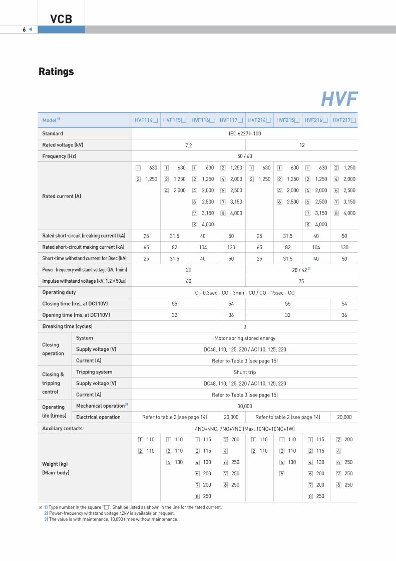
Ratings
VCB6
Model1) HVF114 HVF115 HVF116 HVF117 HVF214 HVF215 HVF216 HVF217
Standard
Rated voltage (kV)
Frequency (Hz)
Rated short-circuit breaking current (kA)
Rated short-circuit making current (kA)
Short-time withstand current for 3sec (kA)
Power-frequency withstand voltage (kV, 1mim)
Impulse withstand voltage (kV, 1.2×50)
Operating duty
Closing time (ms, at DC110V)
Opening time (ms, at DC110V)
Breaking time (cycles)
Auxiliary contacts
7.2
630
1,250
25
65
25
630
1,250
2,000
31.5
82
31.5
630
1,250
2,000
2,500
3,150
4,000
40
104
40
1,250
2,000
2,500
3,150
4,000
50
130
50
630
1,250
25
65
25
630
1,250
2,000
2,500
31.5
82
31.5
630
1,250
2,000
2,500
3,150
4,000
40
104
40
1,250
2,000
2,500
3,150
4,000
50
130
50
12
IEC 62271-100
O - 0.3sec - CO - 3min - CO / CO - 15sec - CO
3
Motor spring stored energy
DC48, 110, 125, 220 / AC110, 125, 220
Refer to Table 3 (see page 15)
Shunt trip
DC48, 110, 125, 220 / AC110, 125, 220
Refer to Table 3 (see page 15)
30,000
4NO+4NC, 7NO+7NC (Max. 10NO+10NC+1W)
※ 1) Type number in the square “”. Shall be listed as shown in the line for the rated current. 2) Power-frequency withstand voltage 42kV is available on request. 3) The value is with maintenance, 10,000 times without maintenance.
Rated current (A)
System
Supply voltage (V)
Current (A)
Tripping system
Supply voltage (V)
Current (A)
Mechanical operation3)
Electrical operation
Closing
operation
Closing &
tripping
control
Operating
life (times)
Weight (kg)
(Main-body)
20
60
55
32
Refer to table 2 (see page 14) Refer to table 2 (see page 14)20,000 20,000
55
32
54
36
54
36
50 / 60
28 / 422)
75
110
110
110
110
130
115
115
130
200
200
250
200
250
250
250
110
110
110
110
130
115
115
130
200
200
250
200
250
250
250
HVF

7Vacuum Circuit Breaker
Model1) HVF314 HVF315 HVF316 HVF611 HVF614 HVF714 HVF705
Standard
Rated voltage (kV)
Frequency (Hz)
Rated short-circuit breaking current (kA)
Rated short-circuit making current (kA)
Short-time withstand current for 3sec (kA)
Power-frequency withstand voltage (kV, 1mim)
Impulse withstand voltage (kV, 1.2×50)
Operating duty
Closing time (ms, at DC110V)
Opening time (ms, at DC110V)
Breaking time (cycles)
Auxiliary contacts
17.5
630
1,250
25
65
25
630
1,250
2,000
2,500
31.5
82
31.5
630
1,250
2,000
2,500
3,150
40
104
40
630
1,250
2,000
12.5
32.5
12.5
630
1,250
2,000
2,500
25
65
25
1,250
2,000
2,500
25
65
25
70
170
75
45
5
1,250
2,500
3,150
31.5
82
31.5
70
170
62
42
5
20,000
363624 / 25.8
IEC 62271-100
32
3
Motor spring stored energy
DC48, 110, 125 / AC110, 125, 220
Refer to Table 3 (see page 15)
Shunt trip
DC48, 110, 125, 220 / AC110, 125, 220
Refer to Table 3 (see page 15)
30,000
Refer to Table 2 (see page 14)
4NO+4NC, 7NO+7NC (Max. 10NO+10NC+1W)
※ 1) Type number in the square “”. Shall be listed as shown in the line for the rated current. 2) Power-frequency withstand voltage 65kV is available on request. 3) The value is with maintenance, 10,000 times without maintenance.
Rated current (A)
System
Supply voltage (V)
Current (A)
Tripping system
Supply voltage (V)
Current (A)
Mechanical operation3)
Electrical operation
Closing
operation
Closing &
tripping
control
Operating
life (times)
Weight (kg)
(Main-body)
38
95
52
50 / 60
50 / 652)
125
68
110
110
110
110
130
115
115
130
200
200
110
110
110
130
145
130
145
180
340
400
400
O - 0.3sec - CO - 3min - CO / CO - 15sec - CO
HVF

Ratings
VCB8
Model1) HVF137 HVF336 HVF7052) HVF706 HVF105 HVF204 HVF606
Standard
Rated voltage (kV)
Frequency (Hz)
Rated short-circuit breaking current (kA)
Rated short-circuit making current (kA)
Short-time withstand current (kA)
Power-frequency withstand voltage (kV, 1mim)
Impulse withstand voltage (kV, 1.2×50)
Operating duty
Closing time (ms, at DC110V)
Opening time (ms, at DC110V)
Breaking time (cycles)
Auxiliary contacts
4.76
1,200
4,000
50
130
50 (2sec)
19
60
75
60
15
1,200
2,000
40
104
40 (2sec)
36
95
75
60
O - 15sec - CO- 3min - CO
10,000
10,000
20,000
20,000 Refer to Table 2 (see page 14)
20,000 30,000 20,000
4NO+4NC, 7NO+7NC (Max. 10NO+10NC+1W)
O - 0.3sec - CO - 3min - CO
1,200
2,000
3,000
31.5
82
31.5 (3sec)
80
150
75
50
1,200
2,000
3,000
40/444)
104
40 (3sec)
80
150
75
50
7.2
630
1,250
2,000
31.5
82
31.5 (3sec)
20
60
75
60
12
630
1,250
2,000
25
65
25 (3sec)
28
75
75
60
24
1,250
2,000
2,500
3,150
40
104
40 (3sec)
50
150
75
60
38
50 / 60
ANSI C37.09 IEC 60056(KR, GL)
IEC 60056(KR, GL) IEC 60056
5
Motor spring stored energy
DC48, 110, 125 / AC110, 125, 220
Refer to Table 3 (see page 15)
Shunt trip
DC48, 110, 125, 220 / AC110, 125, 220
Refer to Table 3 (see page 15)
※ 1) Type number in the square “”. Shall be listed as shown in the line for the rated current. 2) HVF705 type can be applicable to IEC 62271-100 standard. 3) The value is with maintenance, 10,000 times without maintenance. 4) Rated short-circuit breaking current 44kA is available on request.
Rated current (A)
System
Supply voltage (V)
Current (A)
Tripping system
Supply voltage (V)
Current (A)
Mechanical operation3)
Electrical operation
Closing
operation
Closing &
tripping
control
Operating
life (times)
Weight (kg)
(Main-body)
200
300
160
160
340
365
400
340
365
400
150
160
160
150
160
160
340
360
400
400
HVF

9Vacuum Circuit Breaker
※ 1) Type number in the square “”. Shall be listed as shown in the line for the rated current. 2) The value is with maintenance, 10,000 times without maintenance.
HVFModel1) HVF224 HVF225 HVF226 HVF611 HVF614 HVF625 HVF725
Standard
Rated voltage (kV)
Frequency (Hz)
Rated short-circuit breaking current (kA)
Rated short-circuit making current (kA)
Short-time withstand current for 3sec (kA)
Power-frequency withstand voltage (kV, 1mim)
Impulse withstand voltage (kV, 1.2×50)
Operating duty
Closing time (ms, at DC110V)
Opening time (ms, at DC110V)
Breaking time (cycles)
Auxiliary contacts
12
630
1,250
25
65
25
1,250
2,000
31.5
82
31.5
1,250
2,000
2,500
3,150
40
104
40
630
1,250
12.5
32.5
12.5
630
1,250
2,000
25
65
25
630
1,250
2,000
2,500
3,150
31.5
80
31.5
65
125
1,250
2,000
2,500
3,150
31.5
81.9
31.5
24 24 40.5
GOST-R 52565-06 / IEC 62271-100
Motor spring stored energy
DC48, 110, 125, 220 / AC110, 125, 220
Refer to Table 3 (see page 15)
Shunt trip
DC48, 110, 125, 220 / AC110, 125, 220
Refer to Table 3 (see page 15)
Refer to Table 2 (see page 14)
Rated current (A)
System
Supply voltage (V)
Current (A)
Tripping system
Supply voltage (V)
Current (A)
Mechanical operation2)
Electrical operation
Closing
operation
Closing &
tripping
control
Operating
life (times)
Weight (kg)
(Main-body)
42
75
55
32
3
30,000 20,000
68
32
3
70
40
5
45-60
35-45
3
65
125
95
190
50
O - 0.3sec - CO - 3min - CO / CO - 15sec - CO
4NO+4NC, 7NO+7NC (Max. 10NO+10NC+1W)
O - 0.3 sec - CO - 3min - CO / CO - 15sec - CO
4NO+4NC, 7NO+7NC (Max. 10NO+10NC+1W)
O - 0.3sec - CO - 3min - CO
6NO+6NC
110
110
110
130
115
130
200
200
110
110
110
130
145
145
150
170
175
175
280
300
340
360

Ratings
VCB10
Model HVG1099 HVG1011 HVG1131 HVG1132 HVG1141 HVG1142
Standard
Rated voltage (kV)
Frequency (Hz)
Rated current (A)
Rated short-circuit breaking current (kA)
Rated short-circuit making current (kA)
Short-time withstand current for 1sec (kA)
Power-frequency withstand voltage (kV, 1mim)
Impulse withstand voltage (kV, 1.2×50)
Operating duty
Closing time (ms, at DC110V)
Opening time (ms, at DC110V)
Breaking time (cycles)
Auxiliary contacts
400
8
20
8
630
12.5
32.5
12.5
O - 0.3sec - CO - 3min - CO O - 0.3sec - CO - 3min - CO / CO - 15sec - CO
52
52
63
67
65
70
65
70
65
70
65
70
630 1,250 630 1,250
20
52
20
25
65
25
IEC 62271-100
7.2
50 / 60
Motor spring stored energy
DC48, 110, 125, 220 / AC110, 125, 220
Refer to Table 3 (see page 15)
Shunt trip
DC48, 110, 125, 220 / AC110, 125, 220
Refer to Table 3 (see page 15)
20,000
Refer to Table 2 (see page 14)
4NO+4NC, 7NO+7NC (Max. 10NO+10NC+1W)
System
Supply voltage (V)
Current (A)
Tripping system
Supply voltage (V)
Current (A)
Mechanical operation1)
Electrical operation
Fixed type
Draw-out type
Closing
operation
Closing &
tripping
control
Operating
life (times)
Weight (kg)
20
60
32
22
3
HVG
※ 1) The value is with maintenance, 10,000 times without maintenance.

11Vacuum Circuit Breaker
Type of Mounting
Hyundai vacuum circuit breakers offer various solutions for mounting with fixed and draw-out types.The draw-out type breakers consist of truck, mechanical interlock, control terminal, and various accessaries.
<Fig.8> GS type (HVF)
<Fig.5> XA type (HVF) <Fig.6> ES type (HVF)
<Fig.7> FS type (HVF)
※ Besides the standard version of draw-out circuit breakers, specially designed breakers like those for are available on request, such as ANSI standards or retrofit.
XA type
ES type
FS type
SF type
GS type
GE type
Fixed type VCB without cradle
Draw-out type VCB with ES cradle (Without shutter)
Draw-out type VCB with FS cradle (Nonmetallic partition with shutter)
Draw-out type VCB with FS cradle with screw type draw-in/out mechanism
Draw-out type VCB with GS cradle (Metallic partition with shutter and bushing)
Draw-out type VCB with GS cradle with earthing switch

Technical Data [ Application ]
VCB12
HYUNDAI vacuum circuit breakers meet IEC 62271-100, IEC 60056, and ANSI C37.09 standards.
With its consistent short closing and operating times, Hyundai vacuum circuit breakers are especially beneficial in load transfer from one circuit to another without interruption of service. This high speed operation performs synchronizing of the systems to be paralleled at the instant of contact closure as well.According to the relevant standards and breaker types, tests were carried out for the following operating duties.
CO - 15sec - CO O - 0.3sec - CO - 3min - CO O - 15sec - CO - 3min - CO (O: Open, C: Close)
HYUNDAI vacuum circuit breakers may be operated at ambient temperatures between -25 and +40. The rated normal currents are determined according to IEC standards at an ambient temperature of 40.When the breakers are operated at different termperatures, the correction on the operating current must be considered. Fig.9 shows appropriate operating currents at different ambient temperatures.However, the diagram applies only to open type switchgear, so metal enclosed switchgear load currents should be reduced accordingly.
The relatively small capacitive currents of overload transmission lines and cables under no load condition can be safely interrupted without restrike and overvoltage development.
HYUNDAI vacuum circuit breakers are the solution for capacitive applications by switching the circuit without restrike and over voltage. VCB above 7.2kV 20kA can switch ON/OFF up to 400A capacitive load. For the higher than 400A circuit, it shall be informed in advance.
By the special contact materials, the chopping current of the vacuum circuit breakers is only 4A to 5A, so overvoltage is limited when transformers are disconnected at no load condition.
Long electrical lifetime at rated current lets HYUNDAI vacuum circuit breakers be the excellent solution for high voltage motors.A surge absorber is recommended on these motors, which have less insulation level or less than 600A starting current. Even though low surge occurrence is the feature of HYUNDAI vacuum circuit breakers, the motor and the circuit itself can be further protected by the surge absorber.
HYUNDAI vacuum circuit breakers can break the accident current properly at down steam of transformers, generators, and current limit chokes, whose rising rates of transient recovery voltage are higher than IEC Standard, even up to 10kV/.
<Fig.9> Load characteristic curve
1 - 630A 2 - 1,250A3 - 1,600A4 - 2,000A5 - 2,500A 6 - 3,150A
Applicable standards
Switching of capacitors
Switching unloaded transformer
Switching of motors
Interruption of transient recovery voltage
Switching of overload transmission lines and cables
Current carring capacity
Rapid load transfer & Operating duty

13Vacuum Circuit Breaker
Arc Quenching System
A metal-vapor arc discharge in the vacuum is initiated by the current to be interrupted as the contacts open. The current flows through this metal-vapor plasma until the next zero transition.
The arc extinguishes in the vicinity of the current zero, and the conductive metal-vapor condenses within a few microseconds on the metal surfaces.As a result, the dielectric strength in the contact gap is rapidly rebuilt.
The rapid build-up of the dielectric strength at the contact gap enables the arc to be safely extinguished even if contact separation takes place shortly before a current zero transition. The maximum arcing time for the last pole to clear is therefore only up to 15ms.
If the metal vapor arc discharge can be maintained within a certain level, the current is supposed to be chopped prior to current zero.
This chopping current must be controlled in order to prevent build-up of unduly high overvoltages when inductive circuits are switched. The sintered CrCu contact limits the chopping current up to 4A to 5A.
The geometry and size of the contact are designed differently according to breaking current and interrupter type.
<Fig.10> Section view of VI <Fig.11> Arcing time-breaking current curve
1
2
3
4
56
7
8
9
10
11
End flangeCeramic insulatorFixed stemMiddle flangeContact baseContact trip
Act chamberBellows shieldBellowsBearing capMovable stem
123456
7891011
Breaker type
Vacuum circuit breaker
SF6 gas circuit breaker
Oil circuit breaker
Magnetic blaster circuit breaker
Arc voltage (V)
20-200
500-1,000
1,500-3,000
1,500-3,000
<Table 1> Arc quenching medium

Service Life
VCB14
<Fig.12> <Fig.14><Fig.13>
HYUNDAI vacuum circuit breaker needs minimum maintenance due to the simple operating mechanism and robust construction.Vacuum circuit breaker shall be maintained periodically to ensure the perfect performance during mechanical and/or electrical lifetime. Please refer to the instruction manual for the detailed information.
Rated voltage
Rated breaking current
kV
kA
7.27.24.76
HVGHVF
12 17.515 24/25.8 36/40.5 38
Curve number
400A
630A
1,250A
2,000A
2,500A
3,150A
4,000A
40
4
4
4
4
4
25
1
1
40
10
10
31.5
2
2
2
40
4
4
4
4
4
12.5
5
5
25
6
6
6
25
6
6
31.5
2
2
2
2
31.5
2
2
2
25
1
1
40
3
3
3
3
3
31.5
2
2
2
25
1
1
50
11
11
25
9
9
20
9
9
12.5
8
8
8
40
4
4
4
4
31.5
2
2
2
2
<Table 2> Electrical endurance curve number depending on VCB type
Model
HVF / HVG type

15Vacuum Circuit Breaker
Power Consumption & Rated Current
Control voltage Voltage rangeMotor Closing solenoid
DC24V
DC48V
DC60V
DC110V
DC125V
DC220V
AC110V
AC220V
Control current (A)
HVG
-
4.8
3.8
2.4
2.8
1.2
3.6
2.5
HVF
21
10.5
8
4.5
4.5
2.3
6.4
3.2
HVG
-
10.3
8.4
3.3
3.5
2.4
3.3
2.4
HVF
4.0
2.7
1.7
1.3
1.5
0.7
1.3
0.7
HVG
-
10.3
8.4
3.3
3.5
2.4
3.3
2.4
HVF
12.4
6.2
5.0
2.7
2.4
1.4
2.7
1.4
Motor: 85-110%Close: 85-110%Open: 85-110%
HYUNDAI VCB adopts short-time duty charging motor, and the specification is stipulated on Table 3.Since the motor operating time is short, the maximum value and inrush current are disregarded.
Closing solenoid and tripping solenoid operate latching mechanism for VCB springs, so the VCB can be controlled remotely. The specification is mentioned on Table 3. The solenoids unlatch the closing spring and opening spring to close and open the VCB, respectively.
The following versions are available: X: Without control jack A: Double control jack mounted on the breaker body, 4NO+4NC B: Double control jack mounted on the breaker body, 7NO+7NC C: Single control jack leaded out from the breaker body with a 0.8m cable, 4NO+4NC D: Double control jack leaded out from the breaker body with two 0.8m cables, 10NO+10NC
Rating of auxiliary contacts Operating voltage: Max. 250V AC, DC Continuous thermal current: 10A Making current: 30A Switching capacity: 2A at DC220V, T=20ms
Tripping solenoid
<Table 3>
Charging motor
Auxiliary contacts
Power consumption & control voltage
Solenoids
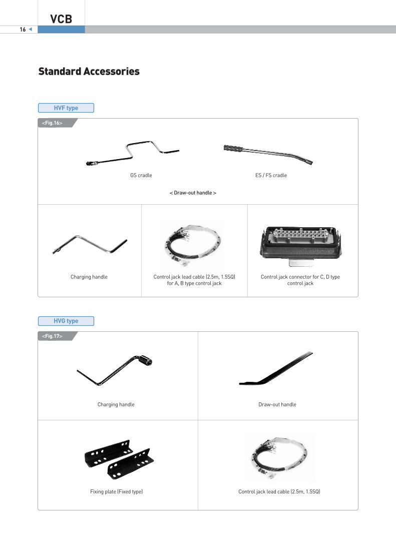
Standard Accessories
VCB16
Charging handle
Charging handle Control jack connector for C, D type control jack
Control jack lead cable (2.5m, 1.5SQ) for A, B type control jack
Control jack lead cable (2.5m, 1.5SQ)
Draw-out handle
Fixing plate (Fixed type)
<Fig.17>
<Fig.16>
< Draw-out handle >
GS cradle ES / FS cradle
HVF type
HVG type

17Vacuum Circuit Breaker
Additional Options
2nd shunt release
Earthing switch
Earthing switch operation indicator contact
Spring charged signal
Using the auxiliary switches operated by the
closing spring, the spring charged status can bedisplayed for visual checking.
Lockout relay
Mechanism operated cell switches (MOC)
CT operated release
Under voltage release
Order code
Rated current
Operation current
Coil registance
HAFS-CT1
0.5A
above 0.45A
20Ω
HAFS-CT2
1.0A
above 0.8A
11Ω
HVF type
Auto secondary jack
Truck operated cell switches (TOC)

Additional Options
VCB18
HVF / HVG type
Order code
Rated input voltage
Rated output voltage
Dimension
HAFS-VC9
AC220V
AC11kV / 22kV
W200×L350×H176
Order code
Rated input voltage
Charging voltage
Ordinary current
Time delay
Frequency
HVFS-T7
AC110V
DC145V
DC2A
within 1.5sec
HVFS-T9
AC220V
DC290V
HVFS-T4
DC110V
DC110V
HVFS-T6
DC220V
DC220V
50 / 60Hz -
Varistor module Position switch
Vacuum checker
Condenser trip device

19Vacuum Circuit Breaker
Control Circuits
Optional circuit
F1: Lockout relayHA: Manual trippingHE: Manual closingK1: Anti-pumping relayM1: MotorP: Stored energy mechanism
S3: Limit switchS41, S42: Limit switch (spring charged signal)S6, S7: Cutout switchV1, V2, V3: Varistor moduleX0: Plug / Socket
Y1: Tripping solenoidY7: Under voltage releaseY9: Closing solenoidR1: ResistorS1: Aux. switchS21, S22: Limit switch
Standard circuit
※ Diagram may be revised without notice.
IEC 62271-100 HVFHVF type

Control Circuits
VCB20
GOST-R 52565-06 / IEC 62271-100
M1: MotorY1: Tripping solenoidR: ResistorX0: Plug connector
S9: Aux. switch (working position)K1: Anti-pumping relayS3, S5, S21, S22: Charging limit switchY9: Closing solenoid
S1: Aux. switchS8: Aux. switch (testing position)
※ The state of the breaker: spring released; open; the truck is in the test position
※ The state of the breaker: spring released; open; the truck is in the test position
HVFHVF 224 , 225 , 226 , 625
HVF 725
※ Diagram may be revised without notice.
HVF type

21Vacuum Circuit Breaker
DC circuit
AC circuit
※ Diagram may be revised without notice.
K1: Anti-pumping relay M1: MotorS3: Limit switchS21: Limit switch
S1: Aux. switchV1: RectifierV2: RectifierR1, R2: Resistor
Y1: Tripping solenoidY9: Closing solenoidXA: Plug/SocketXB: Plug/Socket
IEC 62271-100 HVGHVG type

Dimensions [ HVF fixed type & draw-out type body only ]
VCB22
HVF fixed type (XA)
(Unit: mm)
HVF draw-out type body only (EA, FA, SA, GA)
(Unit: mm)
HVF
Rated Current 630A / 1,250A / 2,000A 2,500A / 3,150A
Detail A
※ Dimensions may be revised without notice.

23Vacuum Circuit Breaker
HVF(Unit: mm)
Model
Dimensions XA/EA/FA/GA EA/FA/GA EA/FA GA
HVF1141
HVF1142
HVF1151
HVF1152
HVF1154
HVF1161
HVF1162
HVF1164
HVF1166/7
HVF2172
HVF2176
HVF2177
HVF2178
HVF1372
HVF2141
HVF2141/2
HVF2151/2
HVF2154
HVF2161/2
HVF2164
HVF2166/7
HVF3141
HVF3142
HVF3151/2
HVF3154
HVF3161/2
HVF3164
HVF3166/7
HVF3362
HVF3364
HVF6111
HVF6112
HVF6141
HVF6142
HVF6144
HVF7142
HVF7144
HVF7146
HVF2241/2
HVF2252
HVF2254
HVF2262
HVF2264/6/7
HVF7252/4/6/7
※ Dimensions may be revised without notice.
A C D E F G J B L K B L P
150 515 230 210 525 447 622 499 40 587 501 50 633
150 515 230 210 525 447 622 499 50 587 501 50 633
165 515 234 275 592 447 675 499 50 587 501 50 633
165 515 234 275 592 447 675 499 50 587 501 50 633
165 515 234 275 592 447 675 499 60 587 501 60 633
165 515 234 275 592 447 675 499 50 587 501 50 633
165 515 234 275 592 447 675 499 50 587 501 50 633
165 515 234 275 592 447 675 499 60 587 501 60 633
210 612 245 310 630 450 738 550 90 587 549 90 633
210 667 245 310 734 450 738 - - - 549 50 610
275 831 245 310 788 450 738 - - - 768 109 613
275 831 245 310 788 450 738 - - - 768 109 613
275 831 245 310 788 450 780 - - - 768 109 613
165 535 234 254 645 447 - - - - - - -
150 515 230 210 525 447 622 499 40 587 501 50 633
150 515 230 210 525 447 622 499 50 587 501 50 633
165 515 234 275 592 447 675 499 50 587 501 50 633
165 515 234 275 592 447 675 499 60 587 501 60 633
165 515 234 275 592 447 675 499 50 587 501 50 633
165 515 234 275 592 447 675 499 60 587 501 60 633
210 612 245 310 630 450 738 550 90 587 549 90 633
150 510 230 210 525 447 610 499 40 587 501 50 673
150 510 230 210 525 447 610 499 50 587 501 50 673
165 515 234 275 592 447 675 499 50 587 501 50 673
165 515 234 275 592 447 675 499 60 587 501 60 673
165 515 234 275 592 447 675 499 50 587 501 50 673
165 515 234 275 592 447 675 499 60 587 501 60 673
210 610 249 310 630 450 738 550 90 587 549 90 673
254 813 234 275 592 447 - - - - - - -
254 813 235 275 592 447 - - - - - - -
210 560 298 310 688 450 774 550 40 587 549 50 784
210 560 298 310 688 450 774 550 50 587 549 50 784
210 560 298 310 688 450 774 550 40 587 549 50 784
210 560 298 310 688 450 774 550 50 587 549 50 784
210 560 298 310 688 450 774 550 60 587 549 60 784
275 845 457 403 984 595 - - - - 845 50 1007
275 845 457 403 984 595 - - - - 845 60 1007
275 845 457 403 984 595 - - - - 845 90 1007
210 588 234 275 582 447 - - - - - - -
210 588 234 275 582 447 - - - - - - -
275 786 249 310 630 447 - - - - - - -
210 588 234 275 582 447 - - - - - - -
275 786 249 310 630 447 - - - - - - -
300 908 583 533 1102 659 - - - - - - -

VCB24
Dimensions
HVF6251, 6252 draw-out type body only
(Unit: mm)
HVF
Type 630A 1,250A
A
B
74
35
87
49
HVF6251, 6252, 6254, 6256, 6257 fixed type
(Unit: mm)
※ Dimensions may be revised without notice.
25Vacuum Circuit Breaker
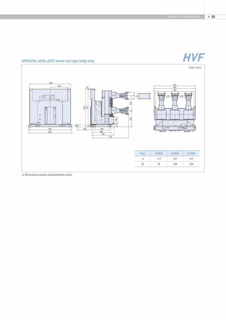
HVF6254, 6256, 6257 draw-out type body only
(Unit: mm)
Type 2,000A 2,500A 3,150A
A
B
117
79
147
109
147
109
HVF
※ Dimensions may be revised without notice.

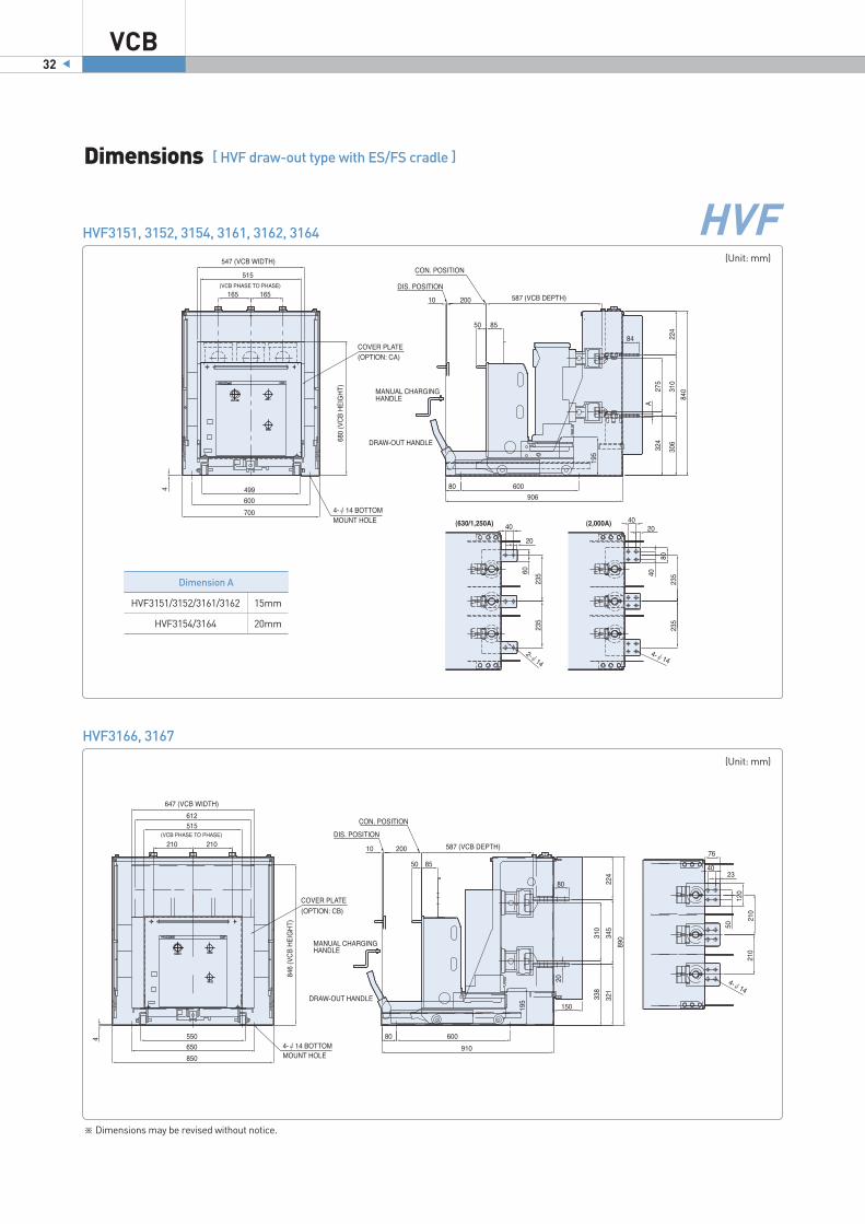
Dimensions [ HVF draw-out type with ES/FS cradle ]
VCB26
(Unit: mm)
Main Circuit Terminal
A B C
(Unit: mm)
DimensionsModel
HVF1141/2
HVF1151/2
HVF1154
HVF1161/2
HVF1164
HVF1166/7
HVF2141/2
HVF2151/2
HVF2154
HVF2161/2
HVF2164
HVF2166/7
HVF3141/2
HVF3451/2
HVF3154
HVF3161/2
HVF3164
HVF6111/2
HVF6141/2
HVF6144
590
612
642
612
620
790
650
650
650
650
650
790
700
700
700
700
700
920
920
920
W H L A B C D G I J K M N Terminal
693
763
763
763
763
819
693
763
763
763
763
855
770
840
840
840
840
972
972
972
830
830
830
830
830
830
910
910
910
910
910
910
966
910
910
910
910
940
940
910
150
165
170
170
170
210
220
235
235
235
235
210
220
235
235
235
235
280(300)
280(300)
300
302
306
306
306
306
321
302
306
306
306
306
321
302
306
306
306
306
370
370
370
245
310
310
310
310
345
245
310
310
310
310
345
245
310
310
310
310
345
345
345
84
84
84
84
84
80
84
84
84
84
84
80
84
84
84
84
84
84
84
84
120
120
120
120
120
120
200
200
200
200
200
200
200
200
200
200
200
230
230
230
80
80
80
80
80
80
80
80
80
80
80
80
80
80
80
80
80
100
100
100
500
500
500
500
500
500
600
600
600
600
600
600
600
600
600
600
600
670
670
670
550
550
550
550
550
650
600
600
600
600
600
650
600
600
600
600
600
650
650
650
60
60
80
60
80
120
60
60
80
60
80
120
60
60
80
60
80
60
60
80
15
15
20
15
20
20
15
15
20
15
20
20
15
15
20
15
20
15
15
20
A
A
B
A
B
C
A
A
B
A
B
C
A
A
B
A
B
A
A
B
※ Dimensions may be revised without notice.
HVF

27Vacuum Circuit Breaker
※ Dimensions may be revised without notice.
HVF1141, 1142
(Unit: mm)
< for breakers manufactured before July 31, 2009 >
< for breakers manufactured from August 1, 2009 >
HVF

VCB28
HVF1151, 1152, 1161, 1162
(Unit: mm)
HVF
Dimensions [ HVF draw-out type with ES/FS cradle ]
< for breakers manufactured before July 31, 2009 >
< for breakers manufactured from August 31, 2009 >
※ Dimensions may be revised without notice.

29Vacuum Circuit Breaker
HVF1154, 1164
(Unit: mm)
HVF1166, 1167
(Unit: mm)
HVF
※ Dimensions may be revised without notice.

VCB30
HVF2141, 2142
(Unit: mm)
HVF2152, 2154, 2162, 2164
(Unit: mm)
HVF
Dimensions [ HVF draw-out type with ES/FS cradle ]
Dimension A
HVF2152/2162
HVF2154/2164
15mm
20mm
※ Dimensions may be revised without notice.
31Vacuum Circuit Breaker
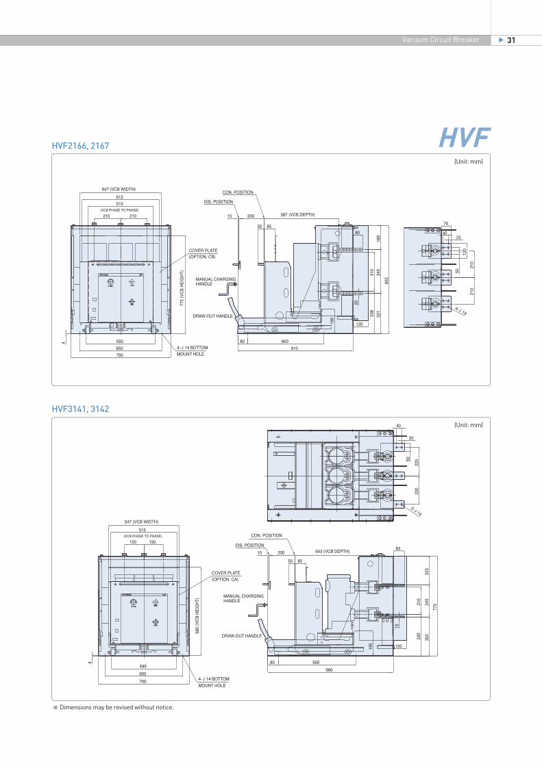
HVF2166, 2167
(Unit: mm)
HVF3141, 3142
(Unit: mm)
HVF
※ Dimensions may be revised without notice.
VCB32
HVF3151, 3152, 3154, 3161, 3162, 3164
(Unit: mm)
HVF3166, 3167
(Unit: mm)
HVF
Dimensions [ HVF draw-out type with ES/FS cradle ]
Dimension A
HVF3151/3152/3161/3162
HVF3154/3164
15mm
20mm
※ Dimensions may be revised without notice.

33Vacuum Circuit Breaker
HVF6111, 6112, 6141, 6142, 6144
(Unit: mm)
HVF
< for breakers manufactured before July 31, 2009 >
< for breakers manufactured from August 1, 2009 >
Dimension A
HVF6111-6142280mm
300mm
ES/FS type
E3/F3 type
Dimension B
HVF6111-6142
HVF6144
15mm
20mm
ES/FS/E3/F3 type
ES/FS type
※ Dimensions may be revised without notice.

VCB34
HVF1141, 1142
(Unit: mm)
HVF1151, 1152, 1161, 1162
(Unit: mm)
HVF
Dimensions [ HVF draw-out type with SF cradle ]
※ Dimensions may be revised without notice.

35Vacuum Circuit Breaker
HVF1154, 1164
(Unit: mm)
HVF1166, 1167
(Unit: mm)
HVF
※ Dimensions may be revised without notice.

VCB36
HVF2151, 2152, 2154, 2161, 2162, 2164
(Unit: mm)
HVF3152, 3154, 3162, 3164
(Unit: mm)
HVF
Dimensions [ HVF draw-out type with SF cradle ]
Dimension A
HVF3152/3262
HVF3154/3164
15mm
20mm
Dimension A
HVF2151/2152/2161/2162
HVF2154/2164
15mm
20mm
※ Dimensions may be revised without notice.

37Vacuum Circuit Breaker
HVF3166, 3167
(Unit: mm)
HVF6111, 6112, 6141, 6142, 6144
(Unit: mm)
HVF
Dimension B
HVF6111/6112/6141/6142
HVF6144
15mm
20mm
※ Dimensions may be revised without notice.

VCB38
Dimensions [ HVF draw-out type with GS cradle ]
(Unit: mm)
HVF
Model a
A
B
C
HVF1141/2141, HVF1142/1151/1152/1162/2141/2152/2162, HVF3152/3162, HVF6111/6112, HVF6141/6142
HVF1154/1164/2154/2164/6144, HVF3166/3167
HVF1167/2167/1166/2166
50
60
60
b
-
40
35
c Detail
2-M12
4-M12
5-M12
(Unit: mm)
DimensionsModelHVF1141/2HVF1151/2HVF1154HVF1161/2HVF1164HVF1166/7HVF1168HVF1178HVF2141/2HVF2168HVF2178HVF2152HVF2154HVF2162HVF2164HVF2167HVF3152HVF3162HVF3166/7HVF6111/2HVF6141/2HVF6144HVF7142/4
150 590 887 773 320 210 237 200 100 400 550 161 142 A 165 590 887 773 324 275 237 200 100 400 550 161 147 A 165 590 907 773 324 275 237 200 100 400 550 161 147 B 165 590 887 773 324 275 237 200 100 400 550 161 147 A 165 590 907 773 324 275 237 200 100 400 550 161 147 B 210 690 1023 743 339 310 264 200 100 400 600 161 196 C 275 1000 1200 765 589 310 279.7 200 50 665 960 154 179.7 - 275 1000 1200 765 589 310 279.7 200 50 665 960 154 179.7 - 150 630 887 773 320 210 237 200 100 400 550 161 142 A 275 1000 1200 765 589 310 279.7 200 50 665 960 154 179.7 - 275 1000 1200 765 589 310 279.7 200 50 665 960 154 179.7 - 165 630 907 773 324 275 237 200 100 400 551 161 147 A 165 630 907 773 324 275 237 200 100 400 551 161 147 B 165 630 907 773 324 275 237 200 100 400 551 161 147 A 165 630 907 773 324 275 237 200 100 400 551 161 147 B 210 690 1023 741 339 310 264 200 100 400 600 161 196 C 210 690 907 823 324 275 368.5 250 100 400 551 161 288.5 A 210 690 907 823 324 275 368.5 250 100 400 551 161 288.5 A 210 750 1023 813 339 310 267 230 100 400 600 161 197 C 210 780 1060 896 388 310 370 300 150 600 650 161 292 A 210 780 1060 896 388 310 370 300 150 600 650 161 292 A 210 780 1060 896 388 310 370 300 150 600 650 161 292 B 275 1090 1450 1270 602.5 403 401.5 420 50 575 950 161 298.5 -
P W H L B C D F G I J K N Terminal
※ Dimensions may be revised without notice.

39Vacuum Circuit Breaker
HVF1141, 1142
(Unit: mm)
HVF1151, 1152, 1154, 1161, 1162, 1164
(Unit: mm)
HVF
※ Dimensions may be revised without notice.

HVF1167, 2167
(Unit: mm)
HVF1168, 1178, 2168, 2178
(Unit: mm)
HVF
Dimensions [ HVF draw-out type with GS cradle ]
VCB40
※ Dimensions may be revised without notice.

41Vacuum Circuit Breaker
HVF2141, 2142
(Unit: mm)
HVF2152, 2154, 2162, 2164
(Unit: mm)
HVF
※ Dimensions may be revised without notice.

HVF3151, 3152, 3154, 3161, 3162, 3164
(Unit: mm)
HVF3166, 3167
(Unit: mm)
HVF
Dimensions [ HVF draw-out type with GS cradle ]
VCB42
※ Dimensions may be revised without notice.

43Vacuum Circuit Breaker
HVF6111, 6112, 6141, 6142, 6144
(Unit: mm)
HVF7142, 7144
(Unit: mm)
HVF
※ Dimensions may be revised without notice.

Dimensions [ HVF draw-out type with MS cradle ]
VCB44
HVF7052, 7054, 7057, 7062, 7064, 7067 (ANSI)
(Unit: mm)
Thickness
Main circuit terminal
80 80 95
3,000A2,000A1,200ARated current
※ Dimensions may be revised without notice.
HVF
※ Standard Acc’y1) MOC Switch 5A+5B2) TOC Switch 3A+3B3) Metal Shutter4) Insulation Boots 6ea5) Auto Control Jack 4NO+4NC
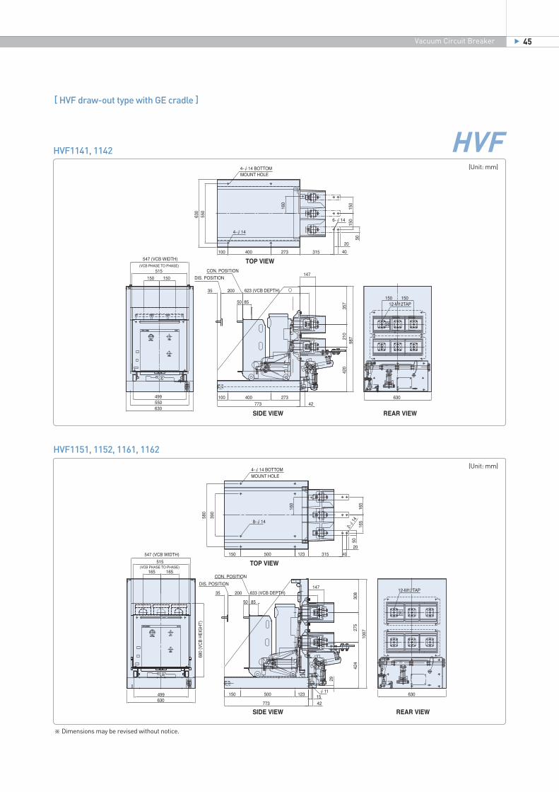
[ HVF draw-out type with GE cradle ]
45Vacuum Circuit Breaker
※ Dimensions may be revised without notice.
HVF1141, 1142
(Unit: mm)
HVF1151, 1152, 1161, 1162
(Unit: mm)
HVF

HVF1154, 1164
(Unit: mm)
HVF1166, 1167, 2166, 2167
(Unit: mm)
HVF
Dimensions [ HVF draw-out type with GE cradle ]
VCB46
※ Dimensions may be revised without notice.

47Vacuum Circuit Breaker
HVF1168, 1178, 2168, 2178
(Unit: mm)
HVF2154, 2164
(Unit: mm)
HVF
※ Dimensions may be revised without notice.

HVF2166, 2167
(Unit: mm)
HVF3167
(Unit: mm)
HVF
Dimensions [ HVF draw-out type with GE cradle ]
VCB48
※ Dimensions may be revised without notice.

49Vacuum Circuit Breaker
HVF6111, 6112, 6141, 6142
(Unit: mm)
HVF6144
(Unit: mm)
HVF
※ Dimensions may be revised without notice.

HVG Fixed type (XA)
Model A B C D E F G H I J K L
HVG1099HVG1011HVG1131/2HVG1141/2
8kA 400A12.5kA 630A20kA 630/1,250A25kA 630/1,250A
443
482 100348 488 155 296 147 151 450 480 390
130
140
61
(Unit: mm)
(Unit: mm)
HVG
HVG draw-out type with ES/FS cradle
※ Dimensions may be revised without notice.
Dimensions [ HVG type ]
VCB50
Model A D E F G H I J K L M N O P
HVG1099HVG1011HVG1131HVG1132HVG1141HVG1142
8kA 400A12.5kA 630A20kA 630A20kA 1,250A25kA 630A25kA 1,250A
96
13670
130
14068 320
540
40500
80464 155 299 660 530 4-14570

51Vacuum Circuit Breaker
HVG draw-out type with GS cradle
Model A B C D E F G H I J K L M
HVG1099
HVG1011
HVG1131
HVG1132
HVG1141
HVG1142
8kA 400A
12.5kA 630A
20kA 630A
20kA 1,250A
25kA 630A
25kA 1,250A
874
550
320
83540 130
14073
525 660
223 75 217
10
15
10
15
640
8
1221775294220
291
(Unit: mm)
※ Dimensions may be revised without notice.
HVG

VCB52
Order Information
HVF C1) ES1)111) 41) 11)
Code Code CodeMounting
StructureCode Code Code
Rated currentIEC ANSI
Type
HVGHVF
ABCDEFGHIJK
XAEAESFAFSSA
SF
GAGSGECSE3F3MAMSWA
BodyBody part of ES cradleES cradle (without shutter)Body part of FS cradleFS cradle (nonmetallic partition with shutter)Body part of SF cradle
FS cradle (nonmetallic partition with shutter)with screw type draw-in/out mechanism)
Body part of GS cradleGS cradle (metallic partition with shutter and bushing)GS cradle with earthing switchGS cradle for marine application (HVF 7.2/12kV)ES cradle for 300mm pole distance (HVF 24kV 630/1250A)FS cradle for 300mm pole distance (HVF 24kV 630/1250A)for HHI standard switchgearGS cradle for 38kV ANSI typeGS cradle for 4.76kV ANSI type
Fixed type
Draw-out
type
130mm140mm150mm165mm178mm210mm250mm254mm275mm300mm350mm
HVGHVF
10112131617071
914567
9124678
Rated voltage
Rated breaking current
Pole distance of VCB body
7.2kV7.2kV12kV
17.5kV24kV
36/38kV36kV
8kA12.5kA25kA
31.5kA40kA50kA
400A630A
1,250A2,000A2,500A3,150A4,000A
400A600A
1,200A2,000A2,500A3,000A4,000A
※ 1) For correct application, please refer to page 54 and 55.
Code Name Specification
HAFS-K1
HAFS-M
HAFS-L0
HAFS-SOL
HVFS-SOL
HVFS-UV
HVFS-UVEHVFS-T4HVFS-T6HVFS-T7HVFS-T9HAFS-ASW4HAFS-ASW7HAFS-ASW10HAFS-L/SHVFS-P/SHAFS-C/MEHAFS-T/MEHAFS-CT1HAFS-CT2HAFS-22JACKHAFS-44JACKHAFS-HANDLEHVFS-EFHANDLEHVFS-MGHANDLEHVFS-VC9
Anti-pumping relayCharging motorLockout relayClosing solenoidTripping solenoidUnder voltage releaseUVT operating mechanismCondensor trip deviceCondensor trip deviceCondensor trip deviceCondensor trip deviceAuxiliary switchAuxiliary switchAuxiliary switchLimit switch (S1)Position switchClosing mechanismTripping mechanismCT operated releaseCT operated releaseControl jackControl jackCharging handleDraw-out handleDraw-out handleVacuum checker
1: DC24V, 2: DC48V, 3: DC60V4: DC110V, 5: DC125V, 6: DC220V7: AC110V, 9: AC220V
DC110VDC220VAC110VAC220V4NO+4NC7NO+7NC10NO+10NC1NO+1NC1NO+1NC
0.5A1A4NO+4NC, fixed type, plug and socket only4NO+4NC, cable type, plug and socket only
ES, FS, SF cradleGS, CS, MS cradleAC220V
Spare parts for HVF type

53Vacuum Circuit Breaker
P2U4
Code Additional optionsApplication
P0U*R*L*V*P21)
KL1)
TP2)
ELC0CPS1C1C2EETCE9CA3)
CB3)
ZZ
Cam for position switchUnder voltage releaseSecond shunt releaseLockout relayVaristor modulePosition switchPosition padlock keyTrip padlock keyElectrical local closingCut-out switchClosing padlock keySpring charged signal (S41)CT operated release 0.5ACT operated release 1AEarthing switch operation indicator contactTrip coil supervision signalBIL 38/95kV for 12kV VCBCover plate / type A4)
Cover plate / type B5)
Special application
HVF/HVGHVFHVFHVF
HVF/HVGHVF/HVGHVF/HVG
HVFHVFHVFHVFHVFHVFHVFHVFHVFHVFHVFHVF
HVF/HVG
4 4 4 C
Code Code Code CodeControl jack
Without control jackAuto jack
Auxiliary switch Structure
Motor control voltage
Closing control voltage
Tripping control voltage
2345679L
2345679L
2345679L
DC48VDC60VDC110VDC125VDC220VAC110VAC220VDC250V
DC48VDC60VDC110VDC125VDC220VAC110VAC220VDC250V
DC48VDC60VDC110VDC125VDC220VAC110VAC220VDC250V
ABCDXW
4NO+4NC7NO+7NC4NO+4NC
10NO+10NC
Fixed on VCB bodyFixed on VCB body
0.8m cable type0.8m cable type
※ *1: DC24V, 2: DC48V, 3: DC60V, 4: DC110V, 5: DC125V, 6: DC220V, 7: AC110V, 9: AC220V 1) Position switch and position padlock cannot be installed at same time. 2) Key is not supplied. 3) For the space between front cover of breaker and ES/FS/SF cradle. 4) Type A: for 7.2-17.5kV up to 31.5kA 2,000A 5) Type B: for 7.2-17.5kV 40/50kA 2,500-4,000A, 24/36kV
Code Name Specification
HAFS-K1
HVGS-M
HVGS-CS
HVGS-TS
HVFS-T4HVFS-T6HVFS-T7HVFS-T9HAFS-ASW4HAFS-ASW7HAFS-ASW10HAFS-L/SHVGS-P/SHVGS-CAMHVGS-22JACKHVGS-44JACKHVGS-PL1099HVGS-PL1131-41HVGS-PL1011HVGS-PL1132-42HVGS-CHANDLEHVGS-DHANDLEHVFS-VC9
Anti-pumping relayCharging motorClosing solenoidTripping solenoidCondensor trip deviceCondensor trip deviceCondensor trip deviceCondensor trip deviceAuxiliary switchAuxiliary switchAuxiliary switchLimit switch (S1)Position switchCam for position switchControl jackControl jackPlug-in contactPlug-in contactPlug-in contactPlug-in contactCharging handleDraw-out handleVacuum checker
1: DC24V, 2: DC48V, 3: DC60V4: DC110V, 5: DC125V, 6: DC220V7: AC110V, 9: AC220V
DC110VDC220VAC110VAC220V4NO+4NC7NO+7NC10NO+10NC1NO+1NC1NO+1NCAttached in breaker body4NO+4NC, fixed type, plug and socket only7NO+7NC, fixed type, plug and socket only8kA 400A20/25kA 630A12.5kA 630A20/25kA 1,250A
AC220V
Spare parts for HVG type

Order Information
VCB54
Type
HVG
HVF
Specification Applicable mounting
Rated voltage
(kV)
Rated breaking
current (kV)
Rated current
(kV)
Pole distance of VCB body
(mm)
Model Order code Fixed
type Draw-out type cradle
*For models and codes not listed, please ask to HHI.
7.2
7.2
12
812.5
20
25
25
31.5
40
50
25
31.5
40
50
400630630
1,250630
1,250630
1,250630
1,2502,000630
1,250
2,000
2,500
3,150
4,0001,2502,0002,5003,1504,000630
1,250630
1,2502,0002,500630
1,250
2,000
2,500
3,150
4,0001,2502,0002,5003,1504,000
130130140140140140150150165165165165165210165210275210275210275275210275275275275150150165165165210165165210165210275210275210275275210275275275275
HVG1099HVG1011HVG1131HVG1132HVG1141HVG1142HVF1141HVF1142HVF1151HVF1152HVF1154HVF1161
HVF1162
HVF1164
HVF1166
HVF1167
HVF1168HVF1172HVF1174HVF1176HVF1177HVF1178HVF2141HVF2142HVF2151HVF2152HVF2154HVF2156HVF2161
HVF2162
HVF2164
HVF2166
HVF2167
HVF2168HVF2172HVF2174HVF2176HVF2177HVF2178
HVG1099 AHVG1011 AHVG1131 BHVG1132 BHVG1141 BHVG1142 BHVF1141 CHVF1142 CHVF1151 DHVF1152 DHVF1154 DHVF1161 DHVF1162 DHVF1162 FHVF1164 DHVF1164 FHVF1164 IHVF1166 FHVF1166 IHVF1167 FHVF1167 IHVF1168 IHVF1172 FHVF1174 IHVF1176 IHVF1177 IHVF1178 IHVF2141 CHVF2142 CHVF2151 DHVF2152 DHVF2154 DHVF2156 FHVF2161 DHVF2162 DHVF2162 FHVF2164 DHVF2164 FHVF2164 IHVF2166 FHVF2166 IHVF2167 FHVF2167 IHVF2168 IHVF2172 FHVF2174 IHVF2176 IHVF2177 IHVF2178 I
XAXAXAXAXAXAXAXAXAXAXAXAXA
XA
XA
XA
XAXAXAXAXAXAXAXAXAXAXAXAXAXA
XA
XA
XA
XAXAXAXAXAXA
EA, ES, FA, FSEA, ES, FA, FSEA, ES, FA, FSEA, ES, FA, FSEA, ES, FA, FSEA, ES, FA, FS
EA, ES, FA, FS, SFEA, ES, FA, FS, SFEA, ES, FA, FS, SFEA, ES, FA, FS, SFEA, ES, FA, FS, SFEA, ES, FA, FS, SFEA, ES, FA, FS, SF
EA, ES, FA, FS, SF
EA, ES, FA, FS, SF
EA, ES, FA, FS, SF
EA, ES, FA, FS, SFEA, ES, FA, FS, SFEA, ES, FA, FS, SFEA, ES, FA, FS, SFEA, ES, FA, FS, SFEA, ES, FA, FS, SFEA, ES, FA, FS, SFEA, ES, FA, FS, SFEA, ES, FA, FS, SFEA, ES, FA, FS, SFEA, ES, FA, FS, SFEA, ES, FA, FS, SFEA, ES, FA, FS, SFEA, ES, FA, FS, SF
EA, ES, FA, FS, SF
EA, ES, FA, FS, SF
EA, ES, FA, FS, SF
EA, ES, FA, FS, SFEA, ES, FA, FS, SFEA, ES, FA, FS, SFEA, ES, FA, FS, SFEA, ES, FA, FS, SFEA, ES, FA, FS, SF
GA, GSGA, GSGA, GSGA, GSGA, GSGA, GSGA, GSGA, GSGA, GSGA, GSGA, GSGA, GSGA, GS
GA, GS
GA, GS
GA, GS
GA, GSGA, GSGA, GSGA, GSGA, GSGA, GSGA, GSGA, GSGA, GSGA, GSGA, GSGA, GSGA, GSGA, GS
GA, GS
GA, GS
GA, GS
GA, GSGA, GSGA, GSGA, GSGA, GSGA, GS
GEGEGEGEGEGEGE
GE
GE
GE
GEGEGEGEGEGEGEGEGEGEGEGEGEGE
GE
GE
GE
GEGEGEGEGEGE
Slection table for rating, pole distance and mounting
1. IEC62271-100
*non-standard, please ask to HHI.
*non-standard, please ask to HHI. *non-standard, please ask to HHI.
*non-standard, please ask to HHI.
*non-standard, please ask to HHI.
*non-standard, please ask to HHI.
*non-standard, please ask to HHI. *non-standard, please ask to HHI.
*non-standard, please ask to HHI.
*non-standard, please ask to HHI.

55Vacuum Circuit Breaker
*For models and codes not listed, please ask to HHI.
2. ANSI
Type
HVF
Specification Applicable mounting
Rated voltage
(kV)
Rated breaking
current (kV)
Rated current
(kV)
Pole distance of VCB body
(mm)
Model Order code Fixed
type Draw-out type cradle
17.5
24
36
25
31.5
40
12.5
25
25
31.5
6301,250630
1,2502,0002,500630
1,250
2,000
2,500
3,150
6301,2502,000630
1,2502,0002,5001,2502,0002,5001,2502,5003,150
150150165165165210165165210165210210210275210210210210210210210275275275275275275
HVF3141HVF3142HVF3151HVF3152HVF3154HVF3156HVF3161
HVF3162
HVF3164
HVF3166
HVF3167
HVF6111HVF6112HVF6114HVF6141HVF6142HVF6144HVF6146HVF7142HVF7144HVF7146HVF7052HVF7056HVF7057
HVF3141 CHVF3142 CHVF3151 DHVF3152 DHVF3154 DHVF3156 FHVF3161 DHVF3162 DHVF3162 FHVF3164 DHVF3164 FHVF3166 FHVF3167 FHVF3167 IHVF6111 FHVF6112 FHVF6114 FHVF6141 FHVF6142 FHVF6144 FHVF6146 FHVF7142 IHVF7144 IHVF7146 IHVF7052 IHVF7056 IHVF7057 I
XAXAXAXAXAXAXAXA
XA
XAXA
XAXAXAXAXAXAXAXAXAXAXAXAXA
EA, ES, FA, FS, SFEA, ES, FA, FS, SFEA, ES, FA, FS, SFEA, ES, FA, FS, SFEA, ES, FA, FS, SFEA, ES, FA, FS, SFEA, ES, FA, FS, SFEA, ES, FA, FS, SF
EA, ES, FA, FS, SF
EA, ES, FA, FS, SFEA, ES, FA, FS, SF
EA, ES, FA, FS, SFEA, ES, FA, FS, SFEA, ES, FA, FS, SFEA, ES, FA, FS, SFEA, ES, FA, FS, SFEA, ES, FA, FS, SFEA, ES, FA, FS, SF
EA, ES, FA, FSEA, ES, FA, FSEA, ES, FA, FSEA, ES, FA, FSEA, ES, FA, FSEA, ES, FA, FS
GA, GSGA, GSGA, GSGA, GSGA, GSGA, GSGA, GSGA, GS
GA, GS
GA, GSGA, GS
GA, GSGA, GSGA, GSGA, GSGA, GSGA, GSGA, GSGA, GSGA, GSGA, GSGA, GSGA, GSGA, GS
GEGEGEGEGEGEGEGE
GE
GEGE
GEGEGEGEGEGEGEGEGEGEGEGEGE
*non-standard, please ask to HHI.
*non-standard, please ask to HHI.
*non-standard, please ask to HHI.
HVF
4.76
15
38
50
40
31.5
40
1,2004,0001,2002,0001,2002,0003,0001,2002,0003,000
178275254254275275275275275275
HVF1372HVF1378HVF3362HVF3364HVF7052HVF7054HVF7057HVF7062HVF7064HVF7067
HVF1372 EHVF1378 IHVF3362 HHVF3364 HHVF7052 IHVF7054 IHVF7057 IHVF7062 IHVF7064 IHVF7067 I
XAXAXAXAXAXAXAXAXAXA
EA, ES, FA, FSEA, ES, FA, FSEA, ES, FA, FSEA, ES, FA, FSEA, ES, FA, FSEA, ES, FA, FSEA, ES, FA, FSEA, ES, FA, FSEA, ES, FA, FSEA, ES, FA, FS
GA, GSGA, GSGA, GSGA, GSGA, GSGA, GSGA, GSGA, GSGA, GSGA, GS
GEGEGEGEGEGEGEGEGEGE
3. IEC60056
HVF
7.2 31.5
12 25
24 40
6301,2502,000630
1,2502,0001,2502,0002,5003,150
165165210165165210275275275275
HVF1051HVF1052HVF1054HVF2041HVF2042HVF2044HVF6062HVF6064HVF6066HVF6067
HVF1051 DHVF1052 DHVF1054 FHVF2041 DHVF2042 DHVF2044 FHVF6062 IHVF6064 IHVF6066 IHVF6067 I
XAXAXAXAXAXAXAXAXAXA
EA, ES, FA, FSEA, ES, FA, FSEA, ES, FA, FSEA, ES, FA, FSEA, ES, FA, FSEA, ES, FA, FSEA, ES, FA, FSEA, ES, FA, FSEA, ES, FA, FSEA, ES, FA, FS
GA, GSGA, GSGA, GSGA, GSGA, GSGA, GSGA, GSGA, GSGA, GSGA, GS
GEGEGEGEGEGEGEGEGEGE

HHIS-WC-LE-B45-04, 2011.12 Designed by M
ERMO
NT
Head Office 1, Jeonha-dong, Dong-gu, Ulsan, Korea Tel: 82-52-202-8101~8 Fax: 82-52-202-8100
Seoul 140-2, Gye-dong, Jongno-gu, Seoul, Korea (Sales & Marketing) Tel: 82-2-746-8519, 7510 Fax: 82-2-746-7441
Atlanta 6100 Atlantic Blvd. Suite 201, Norcross, GA30097, U.S.A. Tel: 1-678-823-7842 Fax: 1-678-823-7553
New Jersey 300 Sylvan Avenue, Englewood Cliffs, NJ, 07632, U.S.A. Tel: 1-201-816-0286, 8028 Fax: 1-201-816-4083
London 2nd Floor, The Triangle, 5-17 Hammersmith Grove, London, W6 0LG, UK Tel: 44-20-8741-0501 Fax: 44-20-8741-5620
Tokyo 8th Fl., Yurakucho Denki Bldg.1-7-1, Yuraku-Cho, Chiyoda-Ku, Tokyo, 100-0006, Japan Tel: 81-3-3212-2076, 3215-7159 Fax: 81-3-3211-2093
Osaka I-Room 5th Fl. Nagahori-Plaza Bldg. 2-4-8, Minami Senba, Chuo-Ku, Osaka, 542-0081, Japan Tel: 81-6-6261-5766, 5767 Fax: 81-6-6261-5818
Riyadh 2nd Floor, the Plaza, P.O.Box 21840 Riyadh 11485, Saudi Arabia Tel: 966-1-462-2331 Fax: 966-1-464-4696
Dubai 205, Building 4, Emaar Square, Sheikh Zayed Road, Pobox 252458, Dubai, UAE Tel: 971-4-425-7995 Fax: 971-4-425-7996
Kuwait Floor 15, Al Sour Tower, Al Sour Street, Al-Qiblah, Kuwait Tel: 965-2291-5354 Fax: 965-2291-5355
Moscow World Trade Center, Ent. 3, #1902, Krasnopresnenskaya Nab.12, Moscow, 123610, Russia Tel: 7-495-258-1381 Fax: 7-495-258-1382
Madrid Paseo De La Castellana 216, Planta 0, 28046 Madrid, Spain Tel: 34-91-732-0454 Fax: 34-91-733-2389
Sofia 1271, Sofia 41, Rojen Blvd., Bulgaria Tel: 359-2-803-3200, 3220 Fax: 359-2-803-3203
Montgomery 201 Folmar Parkway, Montgomery, AL 36105, U.S.A. Tel: 1-334-230-9921 Fax: 1-334-240-6869
Yangzhong No.9 Xiandai Road, Xinba Scientific and Technologic Zone, Yangzhong, Jiangsu, P.R.C. Zip: 212212, China Tel: 86-511-8842-0666, 0212 Fax: 86-511-8842-0668, 0231
www.hyundai-elec.com


