111
Fundamentals of Distance Protection GE Multilin
8/14/2019 88665474 Transmission Line Protection
http://slidepdf.com/reader/full/88665474-transmission-line-protection 1/111
Fundamentals of DistanceProtection
GE Multilin

8/14/2019 88665474 Transmission Line Protection
http://slidepdf.com/reader/full/88665474-transmission-line-protection 2/111
2 /GE /
April-9-12
Outline
• Transmission lin
e introduction
• What is distance protection?
• Non-pilot and pilot schemes
• Redundancy considerations• Security for dual-breaker terminals
• Out-of-step relaying
• Single-pole tripping• Series-compensated lines

8/14/2019 88665474 Transmission Line Protection
http://slidepdf.com/reader/full/88665474-transmission-line-protection 3/111
3 /GE /
April-9-12
Transmission Lines
A Vital Part of the Power System: • Provide path to transfer power between generation and load
• Operate at voltage levels from 69kV to 765kV
• Deregulated markets, economic, environmental requirements
have pushed utilities to operate transmission lines close to theirlimits.

8/14/2019 88665474 Transmission Line Protection
http://slidepdf.com/reader/full/88665474-transmission-line-protection 4/111
4 /GE /
April-9-12
Transmission Lines
Classification of line length depends on:
Source-to-line Impedance Ratio (SIR),
and Nominal voltage
Length considerations:
Short Lines: SIR > 4Medium Lines: 0.5 < SIR < 4
Long Lines: SIR < 0.5

8/14/2019 88665474 Transmission Line Protection
http://slidepdf.com/reader/full/88665474-transmission-line-protection 5/111
5 /GE /
April-9-12
Typical Protection SchemesShort Lines
• Current differential
• Phase comparison
• Permissive Overreach Transfer Trip (POTT)• Directional Comparison Blocking (DCB)

8/14/2019 88665474 Transmission Line Protection
http://slidepdf.com/reader/full/88665474-transmission-line-protection 6/111
6 /
GE /
April-9-12
Typical Protection SchemesMedium Lines
• Phase comparison
• Directional Comparison Blocking (DCB)
• Permissive Underreach Transfer Trip (PUTT)
• Permissive Overreach Transfer Trip (POTT)
• Unblocking
• Step Distance
• Step or coordinated overcurrent• Inverse time overcurrent
• Current Differential
8/14/2019 88665474 Transmission Line Protection
http://slidepdf.com/reader/full/88665474-transmission-line-protection 7/111
7 /
GE /
April-9-12
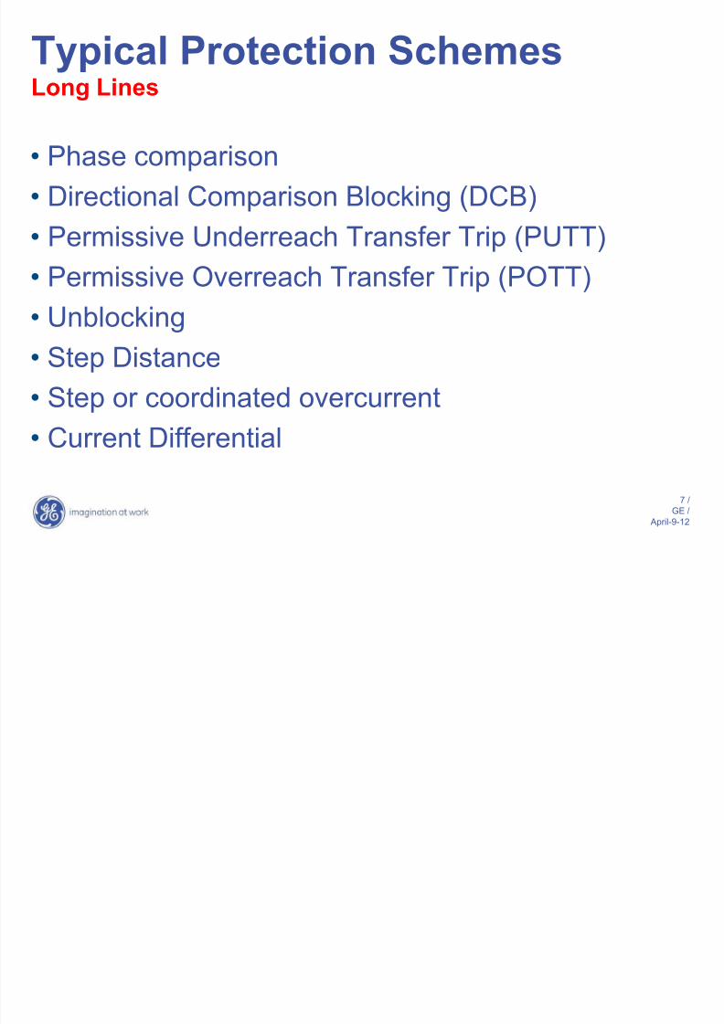
Typical Protection SchemesLong Lines
• Phase comparison
• Directional Comparison Blocking (DCB)
• Permissive Underreach Transfer Trip (PUTT)
• Permissive Overreach Transfer Trip (POTT)
• Unblocking
• Step Distance
• Step or coordinated overcurrent
• Current Differential

8/14/2019 88665474 Transmission Line Protection
http://slidepdf.com/reader/full/88665474-transmission-line-protection 8/111
8 /
GE /
April-9-12
What is distance protection?
For internal faults:> IZ – V and V approximately
in phase (mho)
> IZ – V and IZ approximately in phase(reactance)
RELAY (V,I)
Intended
REACH point
Z
F1
I*Z
V=I*ZF
I*Z - V

8/14/2019 88665474 Transmission Line Protection
http://slidepdf.com/reader/full/88665474-transmission-line-protection 9/111
9 /
GE /
April-9-12
What is distance protection?
For external faults:> IZ – V and V approximately
out of phase (mho)
> IZ – V and IZ approximately out of phase(reactance)
RELAY (V,I)
Intended
REACH point
Z I*Z
V=I*ZF
I*Z - V
F2

8/14/2019 88665474 Transmission Line Protection
http://slidepdf.com/reader/full/88665474-transmission-line-protection 10/111
10 /
GE /
April-9-12
What is distance protection?
RELAY
Intended
REACH point
Z
8/14/2019 88665474 Transmission Line Protection
http://slidepdf.com/reader/full/88665474-transmission-line-protection 11/111
11 /
GE /
April-9-12
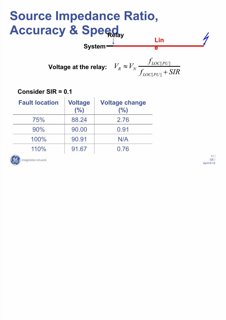
Source Impedance Ratio,Accuracy & Speed
LineSystem
Relay
Voltage at the relay:SIR f
f V V
PU LOC
PU LOC
N R
][
][
Consider SIR = 0.1
Fault location Voltage
(%)
Voltage change
(%)
75% 88.24 2.76
90% 90.00 0.91
100% 90.91 N/A
110% 91.67 0.76
8/14/2019 88665474 Transmission Line Protection
http://slidepdf.com/reader/full/88665474-transmission-line-protection 12/111
12 /
GE /
April-9-12
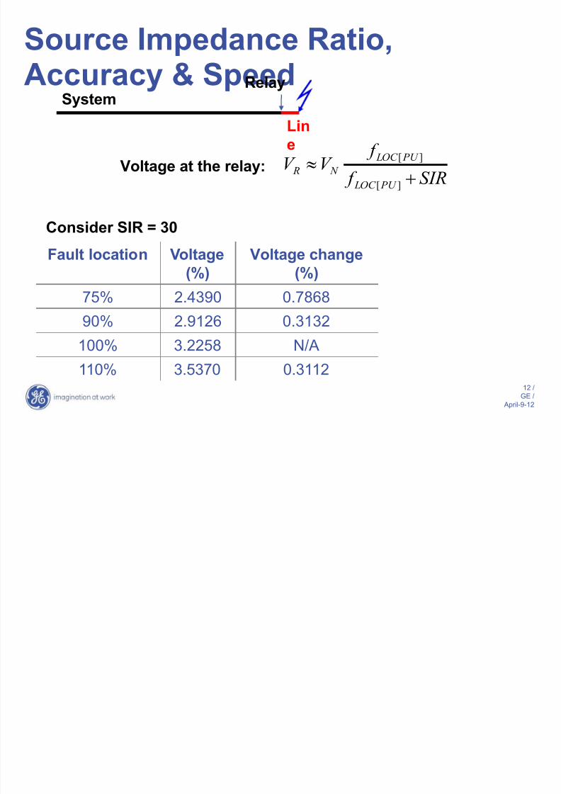
Source Impedance Ratio,Accuracy & Speed
Lin
e
System
Relay
Voltage at the relay:SIR f
f V V
PU LOC
PU LOC
N R
][
][
Consider SIR = 30
Fault location Voltage
(%)
Voltage change
(%)
75% 2.4390 0.7868
90% 2.9126 0.3132
100% 3.2258 N/A
110% 3.5370 0.3112

8/14/2019 88665474 Transmission Line Protection
http://slidepdf.com/reader/full/88665474-transmission-line-protection 13/111
13 /
GE /
April-9-12
Challenges in relay design
> Transients:
– High frequency
– DC offset in currents
– CVT transients involtages
CVT output
0 1 2 3 4
steady-state output
power cycles
-30
-20
-10
0
10
20
30
v o l t a g e ,
V
C1
C2
2
3 5
6
1
4
7
High Voltage Line
S e c o n d a r
y V o l t a g e
O u t p u t
8

8/14/2019 88665474 Transmission Line Protection
http://slidepdf.com/reader/full/88665474-transmission-line-protection 14/111
14 /
GE /
April-9-12
Challenges in relay design
> Transients:
– High frequency
– DC offset in currents
– CVT transients involtages
C1
C2
2
3 5
6
1
4
7
High Voltage Line
S e c o n d a r
y V o l t a g e
O u t p u t
8
CVToutput
0 1 2 3 4
steady-state output
-60
-40
-20
0
20
40
power cycles
v o l t a g e ,
V
60

8/14/2019 88665474 Transmission Line Protection
http://slidepdf.com/reader/full/88665474-transmission-line-protection 15/111
15 /
GE /
April-9-12
Challenges in relay design
-0.5 0 0.5 1 1.5-100
-80
-60
-40
-20
0
20
40
60
80
100
V o l t a g e [ V ]
-0.5 0 0.5 1 1.5-3
-2
-1
0
1
2
3
4
5
C u r r e n t
[ A ]
v A
vB v
C
i A
iB, i
C
-0.5 0 0.5 1 1.5 -100
-50
0
50
100
R e a c t a
n c e c o m p a r a t o r [ V ]
power cycles
S POL
S OP
Sorry… Future (unknown)
> In-phase = internal
fault
> Out-of-phase =external fault

8/14/2019 88665474 Transmission Line Protection
http://slidepdf.com/reader/full/88665474-transmission-line-protection 16/111
16 /
GE /
April-9-12
Transient Overreach
• Fault current generally contains dc offset in
addition to ac power frequency component
• Ratio of dc to ac component of currentdepends on instant in the cycle at which fault
occurred
• Rate of decay of dc offset depends onsystem X/R

8/14/2019 88665474 Transmission Line Protection
http://slidepdf.com/reader/full/88665474-transmission-line-protection 17/111
17 /
GE /
April-9-12
Zone 1 and CVT Transients
Capacitive Voltage Transformers (CVTs) create certainproblems for fast distance relays applied to systems with
high Source Impedance Ratios (SIRs):
> CVT-induced transient voltage components may
assume large magnitudes (up to 30-40%) and last fora comparatively long time (up to about 2 cycles)
> 60Hz voltage for faults at the relay reach point may be
as low as 3% for a SIR of 30
> the signal may be buried under noise

8/14/2019 88665474 Transmission Line Protection
http://slidepdf.com/reader/full/88665474-transmission-line-protection 18/111
18 /
GE /
April-9-12
CVT transients can cause distance relays to overreach.Generally, transient overreach may be caused by:
> overestimation of the current (the magnitude of the
current as measured is larger than its actual value,
and consequently, the fault appears closer than it isactually located),
> underestimation of the voltage (the magnitude of the
voltage as measured is lower than its actual value)
> combination of the above
Zone 1 and CVT Transients
8/14/2019 88665474 Transmission Line Protection
http://slidepdf.com/reader/full/88665474-transmission-line-protection 19/111
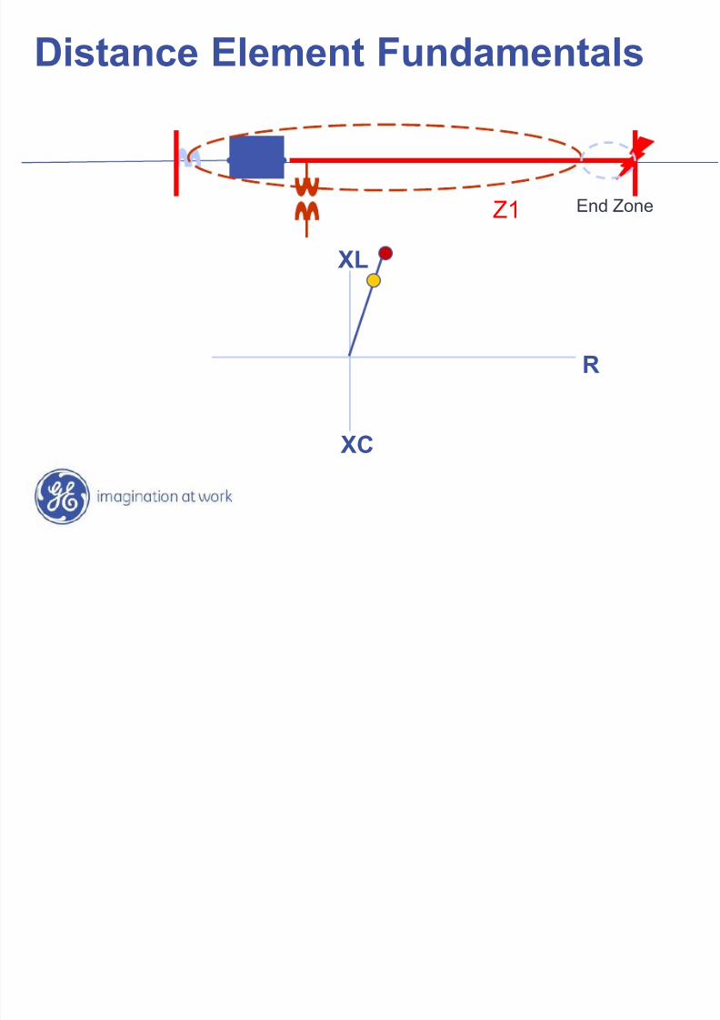
Distance Element Fundamentals
XL
XC
R
Z1 End Zone
8/14/2019 88665474 Transmission Line Protection
http://slidepdf.com/reader/full/88665474-transmission-line-protection 20/111
20 /
GE /
April-9-12
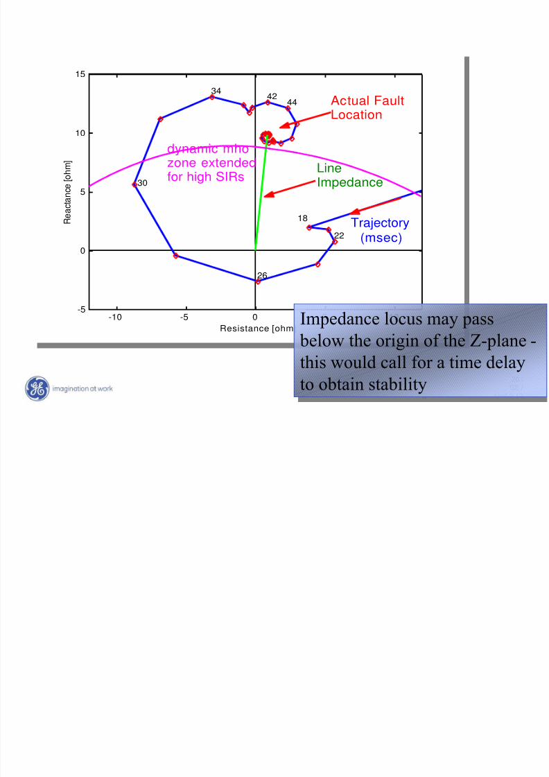
-10 -5 0 5 10-5
0
5
10
15
R e a c t a n c e [ o h m ]
Resistance [ohm]
18
22
26
30
3442 44 Actual Fault
Location
LineImpedance
Trajectory(msec)
dynamic mhozone extendedfor high SIRs
Impedance locus may pass
below the origin of the Z-plane -
this would call for a time delay
to obtain stability

8/14/2019 88665474 Transmission Line Protection
http://slidepdf.com/reader/full/88665474-transmission-line-protection 21/111
21 /
GE /
April-9-12
> apply delay (fixed or adaptable)> reduce the reach
> adaptive techniques and better filtering
algorithms
CVT Transient OverreachSolutions
8/14/2019 88665474 Transmission Line Protection
http://slidepdf.com/reader/full/88665474-transmission-line-protection 22/111
22 /
GE /
April-9-12
> Optimize signal filtering:
– currents - max 3% error due to the dc component
– voltages - max 0.6% error due to CVT transients
> Adaptive double-reach approach
– filtering alone ensures maximum transient
overreach at the level of 1% (for SIRs up to 5) and
20% (for SIRs up to 30)
– to reduce the transient overreach even further an
adaptive double-reach zone 1 has been
implemented
CVT Transients – AdaptiveSolution

8/14/2019 88665474 Transmission Line Protection
http://slidepdf.com/reader/full/88665474-transmission-line-protection 23/111
23 /
GE /
April-9-12
The outer zone 1:
> is fixed at the actual reach
> applies certain security delay to cope with CVT transients
Delayed
Trip
Instantaneous
Trip
R
XThe inner zone 1:
> has its reach dynamically
controlled by the voltage
magnitude
> is instantaneous
CVT Transients – AdaptiveSolution
8/14/2019 88665474 Transmission Line Protection
http://slidepdf.com/reader/full/88665474-transmission-line-protection 24/111
24 /
GE / April-9-12
Desirable Distance RelayAttributesFilters:
> Prefiltering of currents to remove dc decaying transients
– Limit maximum transient overshoot (below 2%)
> Prefiltering of voltages to remove low frequency transients
caused by CVTs – Limit transient overreach to less than 5% for an SIR of
30
> Accurate and fast frequency tracking algorithm
> Adaptive reach control for faults at reach points

8/14/2019 88665474 Transmission Line Protection
http://slidepdf.com/reader/full/88665474-transmission-line-protection 25/111
25 /
GE / April-9-12
Distance Relay Operating Times

8/14/2019 88665474 Transmission Line Protection
http://slidepdf.com/reader/full/88665474-transmission-line-protection 26/111
26 /
GE / April-9-12
Distance Relay Operating Times
20ms
15ms
25ms 30ms
35ms

8/14/2019 88665474 Transmission Line Protection
http://slidepdf.com/reader/full/88665474-transmission-line-protection 27/111
27 /
GE / April-9-12
Distance Relay Operating Times
SLG faults LL faults
3P faults
8/14/2019 88665474 Transmission Line Protection
http://slidepdf.com/reader/full/88665474-transmission-line-protection 28/111
28 /
GE / April-9-12
0 5 10 15 20 25 300
10
20
30
40
50
60
70
80
90
100
M a x i m u m R
a c h [ % ]
SIR
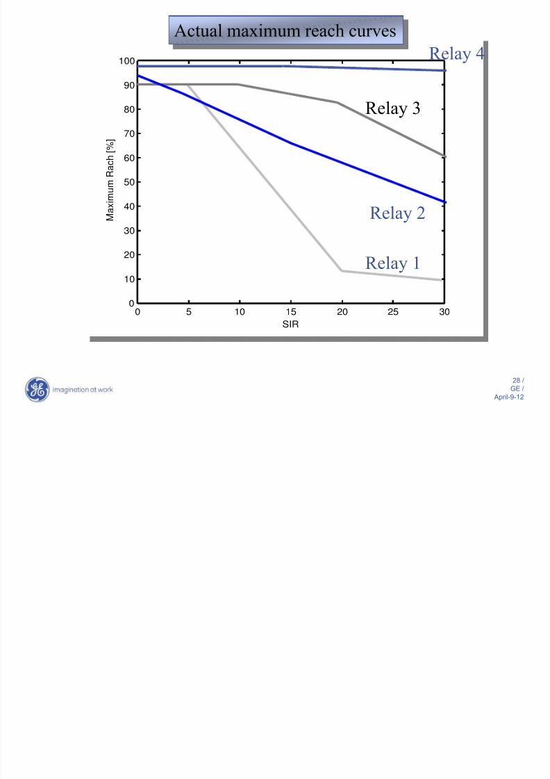
Actual maximum reach curves
Relay 1
Relay 3
Relay 2
Relay 4

8/14/2019 88665474 Transmission Line Protection
http://slidepdf.com/reader/full/88665474-transmission-line-protection 29/111
29 /
GE / April-9-12
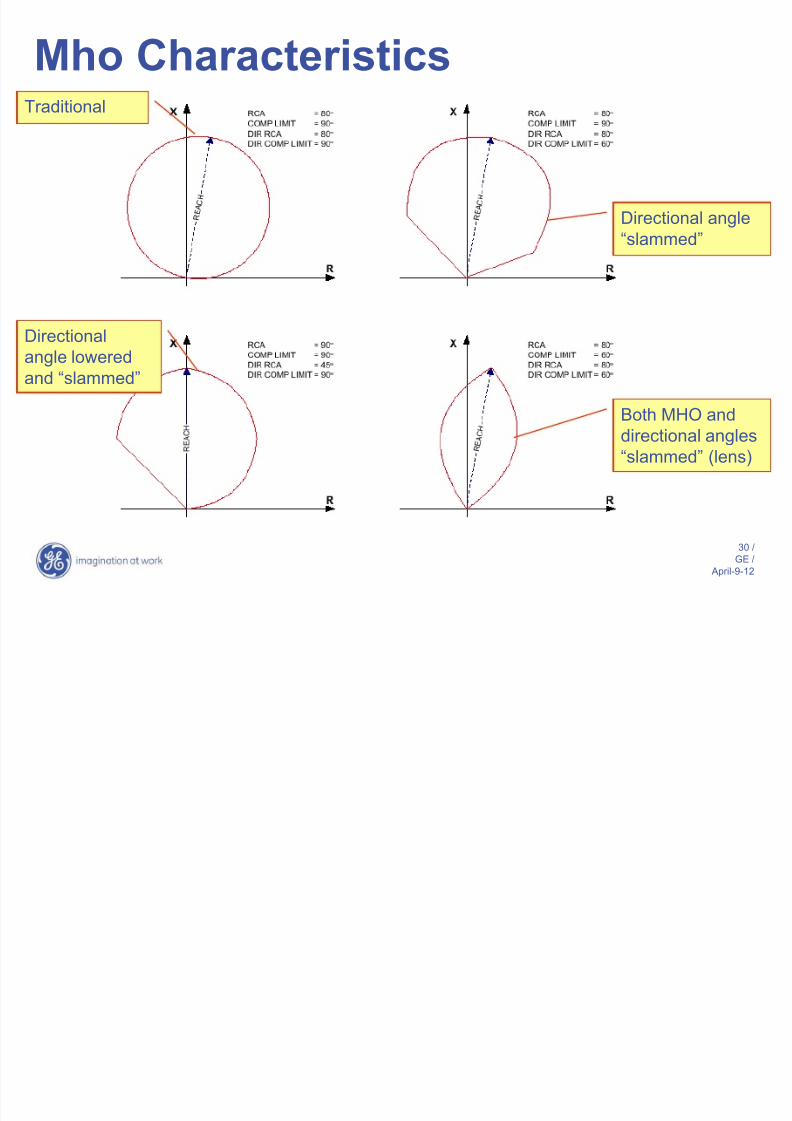
Maximum Torque Angle
• Angle at which mho element has maximum
reach
• Characteristics with smaller MTA willaccommodate larger amount of arc resistance
8/14/2019 88665474 Transmission Line Protection
http://slidepdf.com/reader/full/88665474-transmission-line-protection 30/111
30 /
GE / April-9-12
Traditional
Directional
angle lowered
and “slammed”
Directional angle
“slammed”
Both MHO anddirectional angles
“slammed” (lens)
Mho Characteristics

8/14/2019 88665474 Transmission Line Protection
http://slidepdf.com/reader/full/88665474-transmission-line-protection 31/111
31 /
GE / April-9-12
Typical load characteristic
impedance
+R
Operate
area
No Operate area
+XL
+ = LOOKING INTO LINE
normally considered
forward
Load
Trajectory
Load Swings

8/14/2019 88665474 Transmission Line Protection
http://slidepdf.com/reader/full/88665474-transmission-line-protection 32/111
32 /
GE / April-9-12
Load swing
“Lenticular”Characteristic
Load Swings
8/14/2019 88665474 Transmission Line Protection
http://slidepdf.com/reader/full/88665474-transmission-line-protection 33/111
33 /
GE / April-9-12
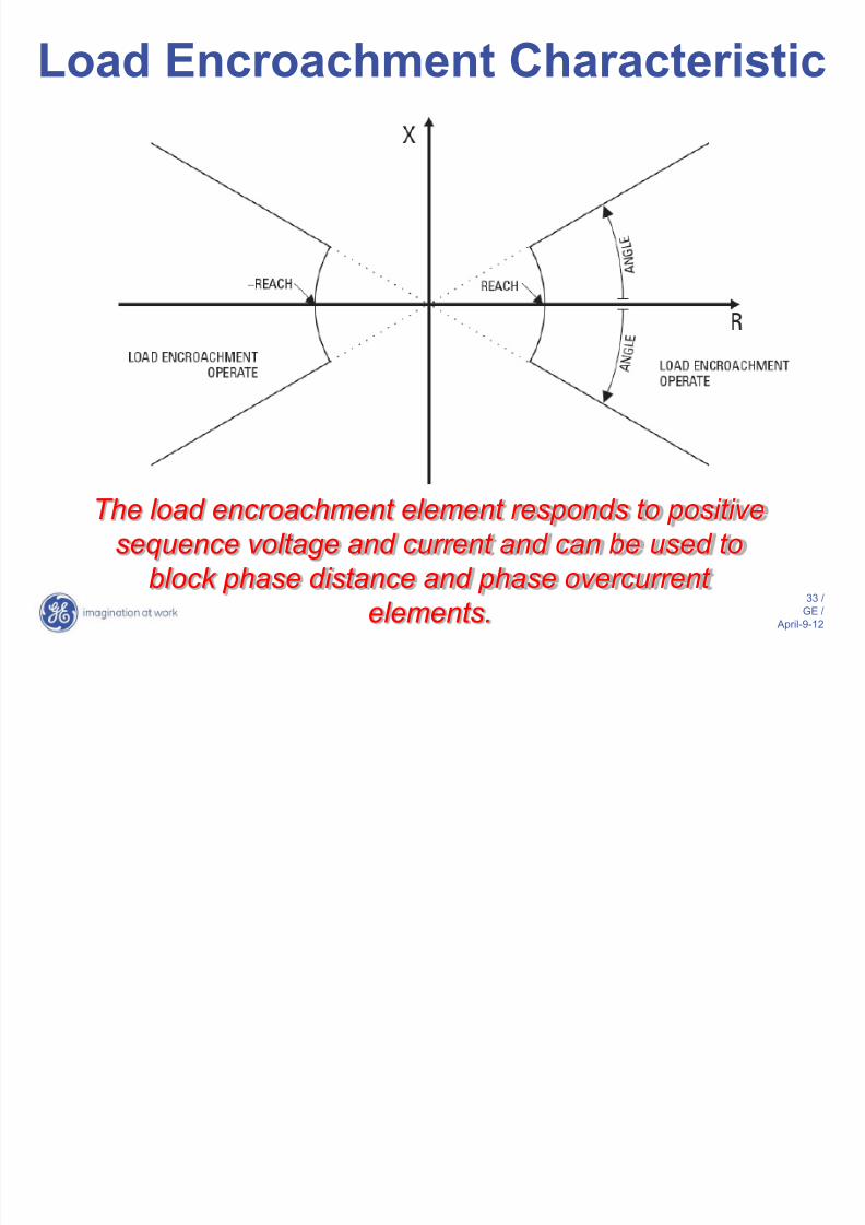
Load Encroachment Characteristic
The load encroachment element responds to positive
sequence voltage and current and can be used to
block phase distance and phase overcurrent
elements.

8/14/2019 88665474 Transmission Line Protection
http://slidepdf.com/reader/full/88665474-transmission-line-protection 34/111
34 /
GE / April-9-12
Blinders
• Blinders limit the operation of distance relays
(quad or mho) to a narrow region that parallels
and encompasses the protected line
• Applied to long transmission lines, where
mho settings are large enough to pick up on
maximum load or minor system swings
8/14/2019 88665474 Transmission Line Protection
http://slidepdf.com/reader/full/88665474-transmission-line-protection 35/111
35 /
GE / April-9-12
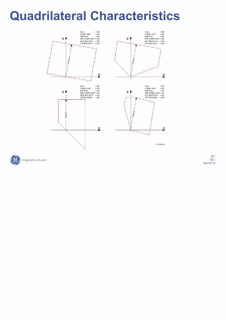
Quadrilateral Characteristics

8/14/2019 88665474 Transmission Line Protection
http://slidepdf.com/reader/full/88665474-transmission-line-protection 36/111
36 /
GE / April-9-12
Ground Resistance
(Conductor falls on ground)
R Resultant impedance outside of
the mho operating region
Quadrilateral Characteristics

8/14/2019 88665474 Transmission Line Protection
http://slidepdf.com/reader/full/88665474-transmission-line-protection 37/111
37 /
GE / April-9-12
Mho Quadrilateral
Better coverage for
ground faults due
to resistance added
to return path
Lenticular
Used for phase elements
with long heavily loaded
lines heavily loaded
Standard for phase
elements
JX
R
Distance Characteristics -Summary

8/14/2019 88665474 Transmission Line Protection
http://slidepdf.com/reader/full/88665474-transmission-line-protection 38/111
38 /
GE / April-9-12
Distance Element Polarization
The following polarization quantities are commonly
used in distance relays for determining directionality:
• Self-polarized
• Memory voltage
• Positive sequence voltage
• Quadrature voltage
• Leading phase voltage

8/14/2019 88665474 Transmission Line Protection
http://slidepdf.com/reader/full/88665474-transmission-line-protection 39/111
39 /
GE / April-9-12
Memory Polarization
> Positive-sequence memorized voltage is used for
polarizing:
– Mho comparator (dynamic, expanding Mho)
– Negative-sequence directional comparator (Ground
Distance Mho and Quad)
– Zero-sequence directional comparator (Ground
Distance MHO and QUAD)
– Directional comparator (Phase Distance MHO and
QUAD)
> Memory duration is a common distance settings (all zones,
phase and ground, MHO and QUAD)

8/14/2019 88665474 Transmission Line Protection
http://slidepdf.com/reader/full/88665474-transmission-line-protection 40/111
40 /
GE / April-9-12
Memory Polarization jX
R
Dynamic MHO characteristic for a reverse faul
Dynamic MHO characteristic for a forward fa
Impedance During Close-up Faults
Static MHO characteristic (memory not established or
expired)
ZL
ZS

8/14/2019 88665474 Transmission Line Protection
http://slidepdf.com/reader/full/88665474-transmission-line-protection 41/111
41 /
GE / April-9-12
Memory Polarization
Memory Polarization…Improved ResistiveCovera e
Dynamic MHO characteristic for a forward faul
Static MHO characteristic (memory not established or
expired)
jX
R
ZL
ZS
RL
8/14/2019 88665474 Transmission Line Protection
http://slidepdf.com/reader/full/88665474-transmission-line-protection 42/111
42 /
GE / April-9-12
Choice of Polarization
• In order to provide flexibility modern distance
relays offer a choice with respect to
polarization of ground overcurrent direction
functions:
–Voltage polarization
–Current polarization
–Dual polarization

8/14/2019 88665474 Transmission Line Protection
http://slidepdf.com/reader/full/88665474-transmission-line-protection 43/111
43 /
GE / April-9-12
Ground Directional Elements> Pilot-aided schemes using ground mho distance relays
have inherently limited fault resistance coverage> Ground directional over current protection using either
negative or zero sequence can be a useful supplement togive more coverage for high resistance faults
> Directional discrimination based on the ground quantities is
fast:
– Accurate angular relations between the zero andnegative sequence quantities establish very quicklybecause:
During faults zero and negative-sequencecurrents and voltages build up from very lowvalues (practically from zero)
The pre-fault values do not bias the developing
fault components in any direction
S

8/14/2019 88665474 Transmission Line Protection
http://slidepdf.com/reader/full/88665474-transmission-line-protection 44/111
44 /
GE / April-9-12
Distance Schemes
Pilot Aided
Schemes
No Communicationbetween Distance
Relays
Communicationbetween Distance
relays
Non-Pilot Aided
Schemes
(Step Distance)

8/14/2019 88665474 Transmission Line Protection
http://slidepdf.com/reader/full/88665474-transmission-line-protection 45/111
45 /
GE / April-9-12
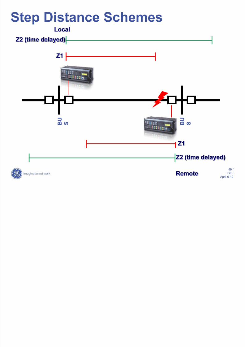
Step Distance Schemes• Zone 1:
– Trips with no intentional time delay – Underreaches to avoid unnecessary operation for faults
beyond remote terminal
– Typical reach setting range 80-90% of ZL
• Zone 2: – Set to protect remainder of line
– Overreaches into adjacent line/equipment
– Minimum reach setting 120% of ZL
– Typically time delayed by 15-30 cycles• Zone 3:
– Remote backup for relay/station failures at remoteterminal
– Reaches beyond Z2, load encroachment a consideration

8/14/2019 88665474 Transmission Line Protection
http://slidepdf.com/reader/full/88665474-transmission-line-protection 46/111
46 /
GE / April-9-12
Z1
Z1
Local
Remote
Step Distance Schemes

8/14/2019 88665474 Transmission Line Protection
http://slidepdf.com/reader/full/88665474-transmission-line-protection 47/111
47 /
GE / April-9-12
Z1
Z1
End
Zone
End
Zone
Local
Remote
Step Distance Schemes

8/14/2019 88665474 Transmission Line Protection
http://slidepdf.com/reader/full/88665474-transmission-line-protection 48/111
48 /
GE / April-9-12
Z1
Z1
Breaker
Tripped
Breaker
Closed
Local
Remote
Step Distance Schemes
8/14/2019 88665474 Transmission Line Protection
http://slidepdf.com/reader/full/88665474-transmission-line-protection 49/111
49 /
GE / April-9-12
Z1
Z1
Z2 (time delayed)
Remote
Local
Step Distance Schemes
Z2 (time delayed)

8/14/2019 88665474 Transmission Line Protection
http://slidepdf.com/reader/full/88665474-transmission-line-protection 50/111
50 /
GE / April-9-12
Z1
Z2 (time delayed)
Step Distance Schemes
Z3 (remote backup)

8/14/2019 88665474 Transmission Line Protection
http://slidepdf.com/reader/full/88665474-transmission-line-protection 51/111
51 /
GE / April-9-12
Step Distance Protection

8/14/2019 88665474 Transmission Line Protection
http://slidepdf.com/reader/full/88665474-transmission-line-protection 52/111
52 /
GE / April-9-12
Local Relay –
Z2
Zone 2 PKP
Local Relay Remote Relay
Remote Relay –
Z4
Zone 4 PKP
Over Lap
Distance Relay Coordination

8/14/2019 88665474 Transmission Line Protection
http://slidepdf.com/reader/full/88665474-transmission-line-protection 53/111
53 /
GE / April-9-12
Communication
Channel
Local
Relay
Remote Relay
Need For Pilot Aided Schemes

8/14/2019 88665474 Transmission Line Protection
http://slidepdf.com/reader/full/88665474-transmission-line-protection 54/111
54 /
GE / April-9-12
Pilot Communications Channels
• Distance-based pilot schemes traditionally utilizesimple on/off communications between relays, butcan also utilize peer-to-peer communications andGOOSE messaging over digital channels
• Typical communications media include: – Pilot-wire (50Hz, 60Hz, AT)
– Power line carrier
– Microwave
– Radio
– Optic fiber (directly connected or multiplexedchannels)

8/14/2019 88665474 Transmission Line Protection
http://slidepdf.com/reader/full/88665474-transmission-line-protection 55/111
55 /
GE / April-9-12
Distance-based Pilot Protection
Pil t Aid d Di t B d S h

8/14/2019 88665474 Transmission Line Protection
http://slidepdf.com/reader/full/88665474-transmission-line-protection 56/111
56 /
GE / April-9-12
Pilot-Aided Distance-Based Schemes
DUTT – Direct Under-reaching Transfer Trip
PUTT – Permissive Under-reaching Transfer
Trip
POTT – Permissive Over-reaching Transfer Trip
Hybrid POTT – Hybrid Permissive Over-
reaching Transfer Trip
DCB – Directional Comparison Blocking
Scheme
DCUB – Directional Comparison Unblocking
Scheme
Di t U d hi T f T i
8/14/2019 88665474 Transmission Line Protection
http://slidepdf.com/reader/full/88665474-transmission-line-protection 57/111
57 /
GE / April-9-12
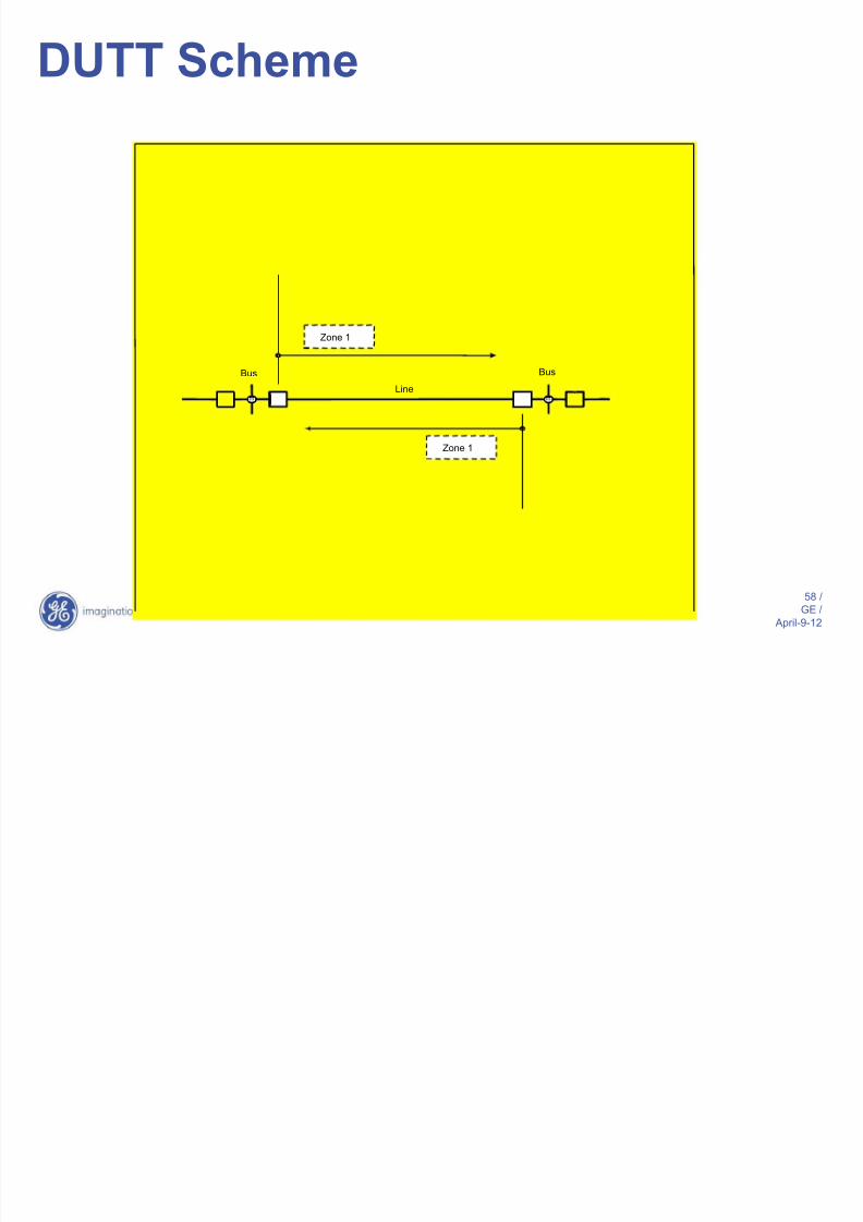
Direct Underreaching Transfer Trip(DUTT)
• Requires only underreaching (RU) functions whichoverlap in reach (Zone 1).
• Applied with FSK channel
– GUARD frequency transmitted during normalconditions
– TRIP frequency when one RU function operates
• Scheme does not provide tripping for faults beyond
RU reach if remote breaker is open or channel isinoperative.
• Dual pilot channels improve security
DUTT S h
8/14/2019 88665474 Transmission Line Protection
http://slidepdf.com/reader/full/88665474-transmission-line-protection 58/111
58 /
GE / April-9-12
Bus
Line
Bus
Zone 1
Zone 1
DUTT Scheme
P i i U d hi

8/14/2019 88665474 Transmission Line Protection
http://slidepdf.com/reader/full/88665474-transmission-line-protection 59/111
59 /
GE / April-9-12
Permissive UnderreachingTransfer Trip (PUTT)
• Requires both under (RU) and overreaching
(RO) functions
• Identical to DUTT, with pilot tripping signal
supervised by RO (Zone 2)
PUTT S h

8/14/2019 88665474 Transmission Line Protection
http://slidepdf.com/reader/full/88665474-transmission-line-protection 60/111
60 /
GE / April-9-12
Bus
Line
Bus
Zone 1
Zone 2
Zone 2
Zone 1
To protect end of line
& Local TripZone 2
Rx PKP
OR Zone 1
PUTT Scheme
P i i O hi T f
8/14/2019 88665474 Transmission Line Protection
http://slidepdf.com/reader/full/88665474-transmission-line-protection 61/111
61 /
GE / April-9-12
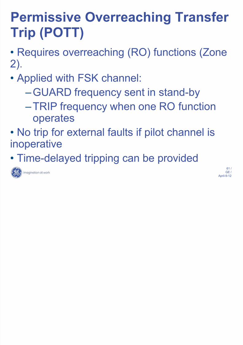
Permissive Overreaching TransferTrip (POTT)
• Requires overreaching (RO) functions (Zone2).
• Applied with FSK channel:
–GUARD frequency sent in stand-by
–TRIP frequency when one RO functionoperates
• No trip for external faults if pilot channel isinoperative
• Time-delayed tripping can be provided
POTT S h

8/14/2019 88665474 Transmission Line Protection
http://slidepdf.com/reader/full/88665474-transmission-line-protection 62/111
62 /
GE / April-9-12
Bus
Line
Bus
Zone 1
Zone 2
TripLine
Breakers
OR
t
Rx
Tx
AND
(Z1)
(Z1)
o
Zone 1
Zone 2
Zone 2
Zone 1
POTT Scheme
POTT Scheme

8/14/2019 88665474 Transmission Line Protection
http://slidepdf.com/reader/full/88665474-transmission-line-protection 63/111
63 /
GE / April-9-12
POTT Scheme
POTT – Permissive Over-reaching Transfer
TripEnd
Zone
CommunicationChannel
POTT Scheme

8/14/2019 88665474 Transmission Line Protection
http://slidepdf.com/reader/full/88665474-transmission-line-protection 64/111
64 /
GE / April-9-12
Local Relay Remote Relay
Remote
Relay FWD
IGND
Ground Dir OC Fwd
OR
Local Relay – Z2
ZONE 2 PKP
Local Relay
FWD IGND
Ground Dir OC Fwd
OR
TRIP
Remote Relay – Z2
POTT TX
ZONE 2 PKP
POTT RX
Communicatio
n Channel
POTT Scheme
POTT Scheme

8/14/2019 88665474 Transmission Line Protection
http://slidepdf.com/reader/full/88665474-transmission-line-protection 65/111
65 /
GE / April-9-12
POTT TX 4
POTT TX 3
POTT TX 2
POTT TX 1 A to G
B to G
C to G
Multi Phase
Local Relay Remote Relay
POTT RX 4
POTT RX 3
POTT RX 2
POTT RX 1
C om
m uni c a t i on s
C
h a nn e l ( s )
POTT Scheme
POTT Scheme

8/14/2019 88665474 Transmission Line Protection
http://slidepdf.com/reader/full/88665474-transmission-line-protection 66/111
66 /
GE / April-9-12
Local Relay Remote Relay
POTT TX ZONE 2 OR
GND DIR OC FWD
CommunicationChannel
TRIP
GND DIR OC REV GND DIR OC REV POTT RX
StartTimer TimerExpire
GND DIR OC FWD
POTT SchemeCurrent reversal example
POTT Scheme

8/14/2019 88665474 Transmission Line Protection
http://slidepdf.com/reader/full/88665474-transmission-line-protection 67/111
67 /
GE / April-9-12
Local Relay
Open
Remote Relay
Remote FWD
IGND
POTT TX
Remote –
Z2
Communication
Channel
POTT RX
OPEN
POTT TX
Communication
Channel
POTT RX
TRIP
POTT SchemeEcho example
Hybrid POTT

8/14/2019 88665474 Transmission Line Protection
http://slidepdf.com/reader/full/88665474-transmission-line-protection 68/111
68 /
GE / April-9-12
Hybrid POTT
• Intended for three-terminal lines and weak
infeed conditions
• Echo feature adds security during weak
infeed conditions
• Reverse-looking distance and oc elements
used to identify external faults
Hybrid POTT

8/14/2019 88665474 Transmission Line Protection
http://slidepdf.com/reader/full/88665474-transmission-line-protection 69/111
69 /
GE / April-9-12
Bus
Line
Bus
Zone 1
Zone 2
Zone 2
Zone 1 Zone 4
LocalRemote
Weak
system
Hybrid POTT
Directional Comparison Blocking

8/14/2019 88665474 Transmission Line Protection
http://slidepdf.com/reader/full/88665474-transmission-line-protection 70/111
70 /
GE / April-9-12
Directional Comparison Blocking(DCB)
• Requires overreaching (RO) tripping and blocking(B) functions
• ON/OFF pilot channel typically used (i.e., PLC)
– Transmitter is keyed to ON state when blockingfunction(s) operate
– Receipt of signal from remote end blockstripping relays
• Tripping function set with Zone 2 reach or greater• Blocking functions include Zone 3 reverse and low-set ground overcurrent elements
DCB Scheme

8/14/2019 88665474 Transmission Line Protection
http://slidepdf.com/reader/full/88665474-transmission-line-protection 71/111
71 /
GE / April-9-12
Bus
Line
Bus
Zone 1
Zone 2
Zone 2
Zone 1
LocalRemote
DCB Scheme
Directional Comparison Blocking

8/14/2019 88665474 Transmission Line Protection
http://slidepdf.com/reader/full/88665474-transmission-line-protection 72/111
72 /
GE / April-9-12
End Zone
Communication Channel
Directional Comparison Blocking
(DCB)
Directional Comparison Blocking
8/14/2019 88665474 Transmission Line Protection
http://slidepdf.com/reader/full/88665474-transmission-line-protection 73/111
73 /
GE / April-9-12
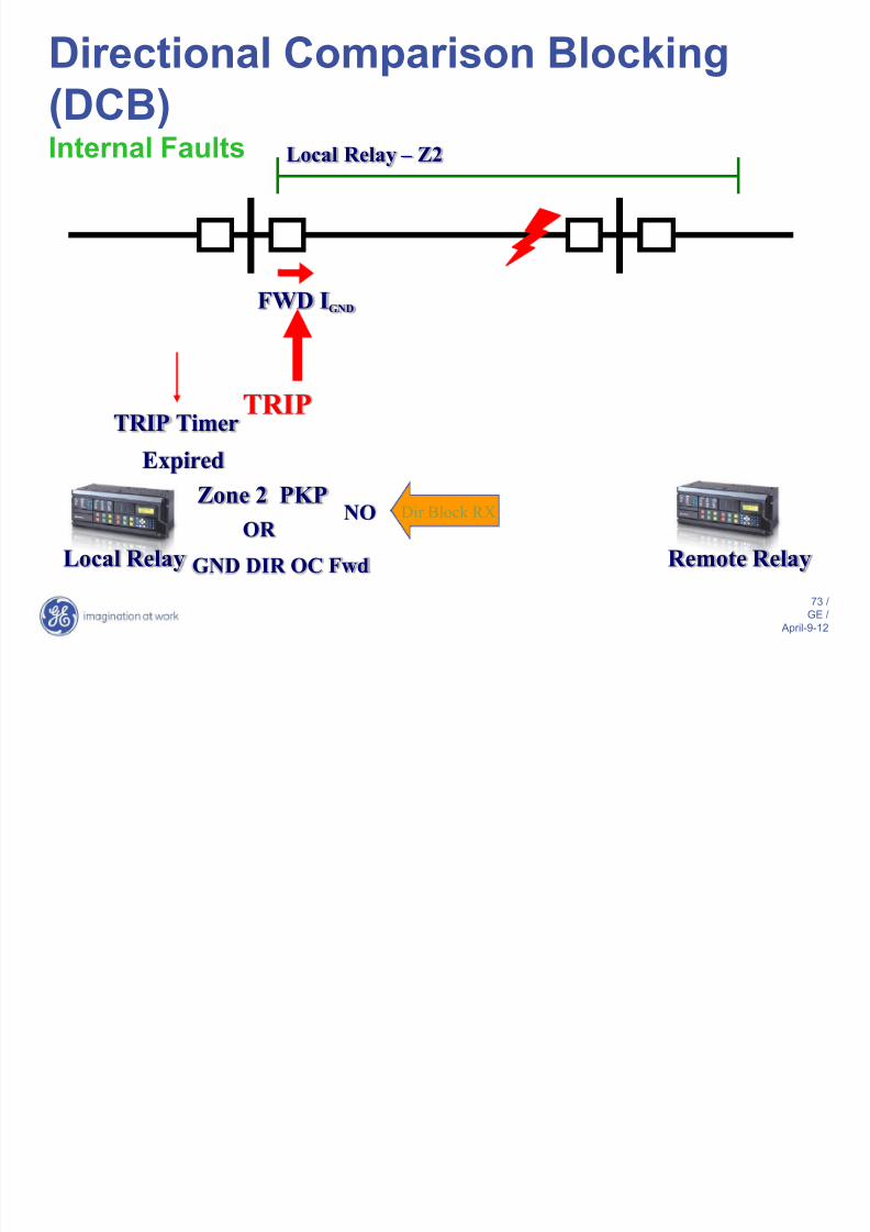
Directional Comparison Blocking
(DCB)Internal Faults
Local Relay Remote Relay
Local Relay –
Z2
Zone 2 PKP
TRIP Timer
Start
FWD IGND
GND DIR OC Fwd
ORDir Block RXNO
TRIP
Expired
Directional Comparison Blocking
8/14/2019 88665474 Transmission Line Protection
http://slidepdf.com/reader/full/88665474-transmission-line-protection 74/111
74 /
GE /
April-9-12
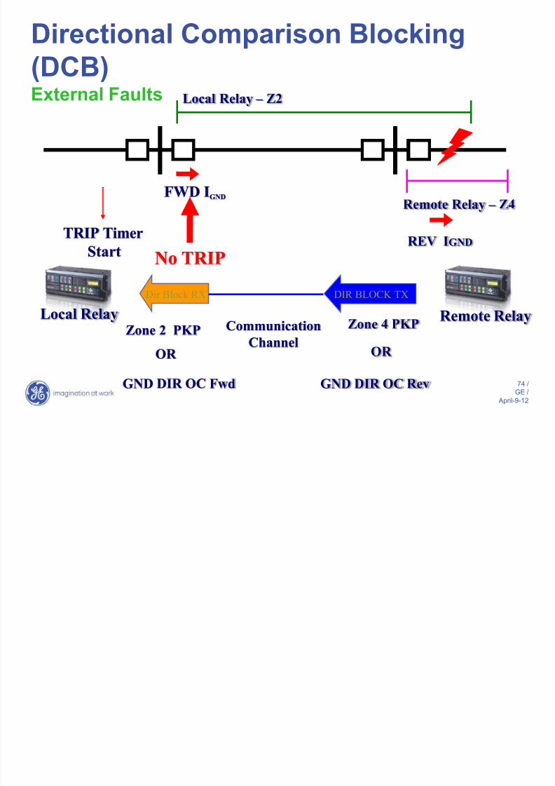
Local Relay Remote Relay
Remote Relay –
Z4
Zone 4 PKP
REV IGND
GND DIR OC Rev
OR
DIR BLOCK TX
Local Relay –
Z2
Zone 2 PKP
Dir Block RX
Communication
Channel
FWD IGND
GND DIR OC Fwd
OR
TRIP Timer
Start No TRIP
Directional Comparison Blocking
(DCB)External Faults
Directional Comparison

8/14/2019 88665474 Transmission Line Protection
http://slidepdf.com/reader/full/88665474-transmission-line-protection 75/111
75 /
GE /
April-9-12
Directional ComparisonUnblocking (DCUB)
• Applied to Permissive Overreaching (POR)schemes to overcome the possibility of carrier signalattenuation or loss as a result of the fault
• Unblocking provided in the receiver when signal islost:
– If signal is lost due to fault, at least onepermissive RO functions will be picked up
– Unblocking logic produces short-duration TRIPsignal (150-300 ms). If RO function not pickedup, channel lockout occurs until GUARD signalreturns
DCUB Scheme

8/14/2019 88665474 Transmission Line Protection
http://slidepdf.com/reader/full/88665474-transmission-line-protection 76/111
76 /
GE /
April-9-12
Bus
Line
Bus
TripLine
Breakers
Tx1(Un-Block)
Forward
Forward
Tx2(Block)
Forward
Rx2
Rx1
to
AND to
AND
AND
AND
Lockout
(Block)
(Un-Block)
DCUB Scheme
Directional Comparison Unblocking

8/14/2019 88665474 Transmission Line Protection
http://slidepdf.com/reader/full/88665474-transmission-line-protection 77/111
77 /
GE /
April-9-12
End Zone
Communication Channel
Directional Comparison Unblocking
(DCUB)
Directional Comparison Unblocking
8/14/2019 88665474 Transmission Line Protection
http://slidepdf.com/reader/full/88665474-transmission-line-protection 78/111
78 /
GE /
April-9-12
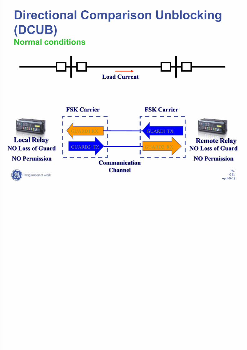
Directional Comparison Unblocking
(DCUB)Normal conditions
Local Relay Remote Relay GUARD1 TXGUARD1 RX
Communication
Channel
GUARD2 TX GUARD2 RXNO Loss of Guard
FSK Carrier FSK Carrier
NO Permission
NO Loss of Guard
NO Permission
Load Current
Directional Comparison Unblocking

8/14/2019 88665474 Transmission Line Protection
http://slidepdf.com/reader/full/88665474-transmission-line-protection 79/111
79 /
GE /
April-9-12
Directional Comparison Unblocking
(DCUB)Normal conditions, channel failure
Local Relay Remote Relay GUARD1 TXGUARD1 RX
Communication
Channel
GUARD2 TX GUARD2 RX
FSK Carrier FSK Carrier
Loss of Guard
Block Timer Started
Loss of Guard
Block Timer Started
Load Current
NO RX
NO RX
Block DCUB
until Guard OK
Expired
Block DCUB
until Guard OK
Expired
Loss of Channel
Directional Comparison Unblocking

8/14/2019 88665474 Transmission Line Protection
http://slidepdf.com/reader/full/88665474-transmission-line-protection 80/111
80 /
GE /
April-9-12
Directional Comparison Unblocking
(DCUB)Internal fault, healthy channel
Local Relay Remote Relay GUARD1 TXGUARD1 RX
Communication
Channel
GUARD2 TX GUARD2 RX
FSK Carrier FSK Carrier
Loss of Guard
Permission
TRIP1 TX
Local Relay – Z2
Zone 2 PKP
TRIP1 RX
TRIP2 TX
TRIP
Remote Relay – Z2
ZONE 2 PKP
TRIP Z1
TRIP2 RX

8/14/2019 88665474 Transmission Line Protection
http://slidepdf.com/reader/full/88665474-transmission-line-protection 81/111
Redundancy Considerations
8/14/2019 88665474 Transmission Line Protection
http://slidepdf.com/reader/full/88665474-transmission-line-protection 82/111
82 /
GE /
April-9-12
Redundancy Considerations
• Redundant protection systems increase dependability of the
system:Multiple sets of protection using same protection principle
and multiple pilot channels overcome individual elementfailure, or
Multiple sets of protection using different protection principles and multiple channels protects against failure ofone of the protection methods.
• Security can be improved using “voting” schemes (i.e., 2-out-of-3), potentially at expense of dependability.
• Redundancy of instrument transformers, battery systems, tripcoil circuits, etc. also need to be considered.
Redundant Communications

8/14/2019 88665474 Transmission Line Protection
http://slidepdf.com/reader/full/88665474-transmission-line-protection 83/111
83 /
GE /
April-9-12
End Zone
Communication Channel 1
Communication Channel 2
Loss of Channel 2
AND Channels:
POTT Less Reliable
DCB Less Secure
OR Channels:
POTT More Reliable
DCB More Secure
More Channel Security More Channel Dependability
Redundant Communications
Redundant Pilot Schemes

8/14/2019 88665474 Transmission Line Protection
http://slidepdf.com/reader/full/88665474-transmission-line-protection 84/111
84 /
GE /
April-9-12
Redundant Pilot Schemes
Pilot Relay Desirable Attributes

8/14/2019 88665474 Transmission Line Protection
http://slidepdf.com/reader/full/88665474-transmission-line-protection 85/111
85 /
GE /
April-9-12
• Integrated functions:
weak infeedecho
line pick-up (SOTF)
• Basic protection elements used to key thecommunication:
distance elements
fast and sensitive ground (zero and negative
sequence) directional IOCs with current,voltage, and/or dual polarization
Pilot Relay Desirable Attributes
Pilot Relay Desirable Attributes

8/14/2019 88665474 Transmission Line Protection
http://slidepdf.com/reader/full/88665474-transmission-line-protection 86/111
86 /
GE /
April-9-12
Pre-programmed distance-based pilot schemes:
Direct Under-reaching Transfer Trip (DUTT)
Permissive Under-reaching Transfer Trip (PUTT)
Permissive Overreaching Transfer Trip (POTT)
Hybrid Permissive Overreaching Transfer Trip (HYBPOTT)
Blocking scheme (DCB)
Unblocking scheme (DCUB)
Pilot Relay Desirable Attributes
Security for dual-breaker terminals

8/14/2019 88665474 Transmission Line Protection
http://slidepdf.com/reader/full/88665474-transmission-line-protection 87/111
87 /
GE /
April-9-12
Security for dual breaker terminals
• Breaker-and-a-half and ring bus terminals arecommon designs for transmission lines.
• Standard practice has been to:
– sum currents from each circuit breaker
externally by paralleling the CTs – use external sum as the line current for
protective relays
• For some close-in external fault events, poor CT
performance may lead to improper operation of linerelays.
Security for dual-breaker terminals

8/14/2019 88665474 Transmission Line Protection
http://slidepdf.com/reader/full/88665474-transmission-line-protection 88/111
88 /
GE /
April-9-12
Security for dual breaker terminals
Accurate CTs preserve thereverse current direction
under weak remote infeed
Security for dual-breaker terminals
8/14/2019 88665474 Transmission Line Protection
http://slidepdf.com/reader/full/88665474-transmission-line-protection 89/111
89 /
GE /
April-9-12
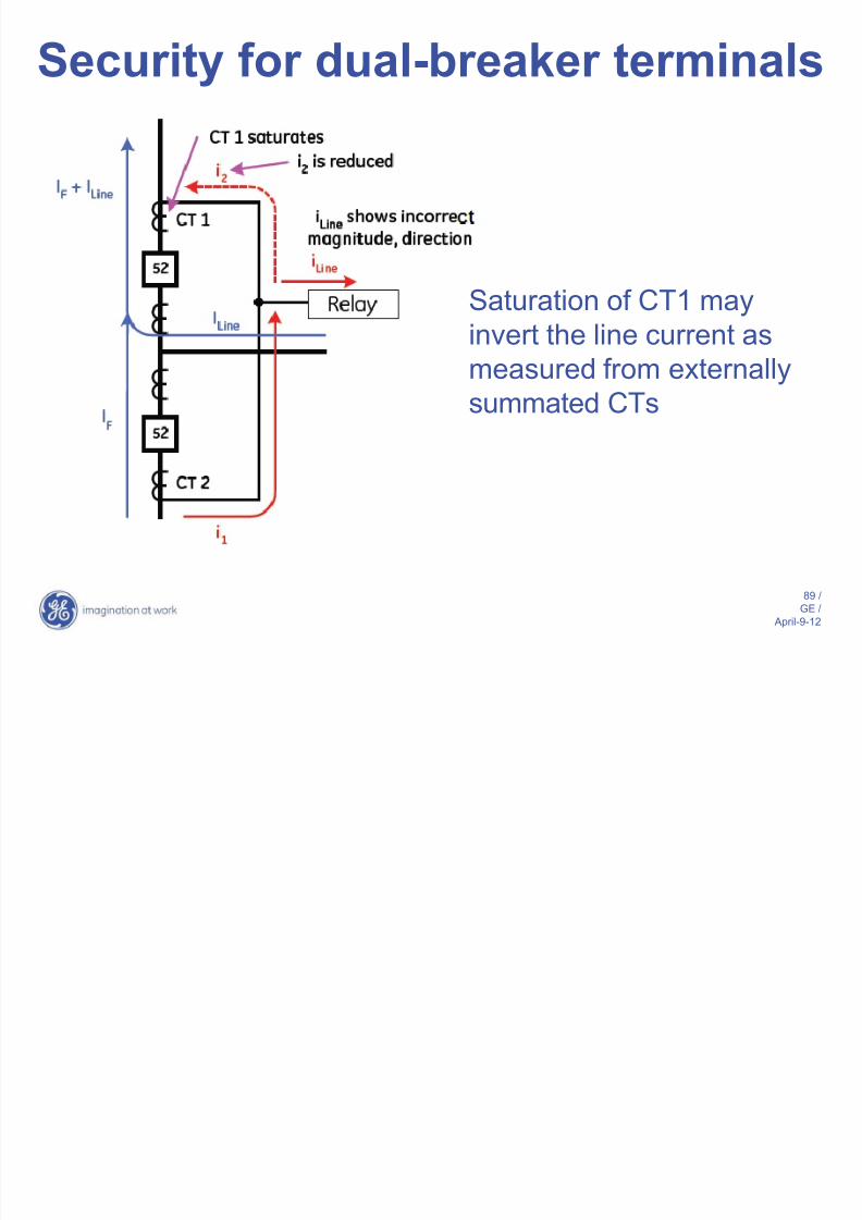
Security for dual breaker terminals
Saturation of CT1 may
invert the line current as
measured from externally
summated CTs
Security for dual-breaker terminals
8/14/2019 88665474 Transmission Line Protection
http://slidepdf.com/reader/full/88665474-transmission-line-protection 90/111
90 /
GE /
April-9-12
Security for dual breaker terminals
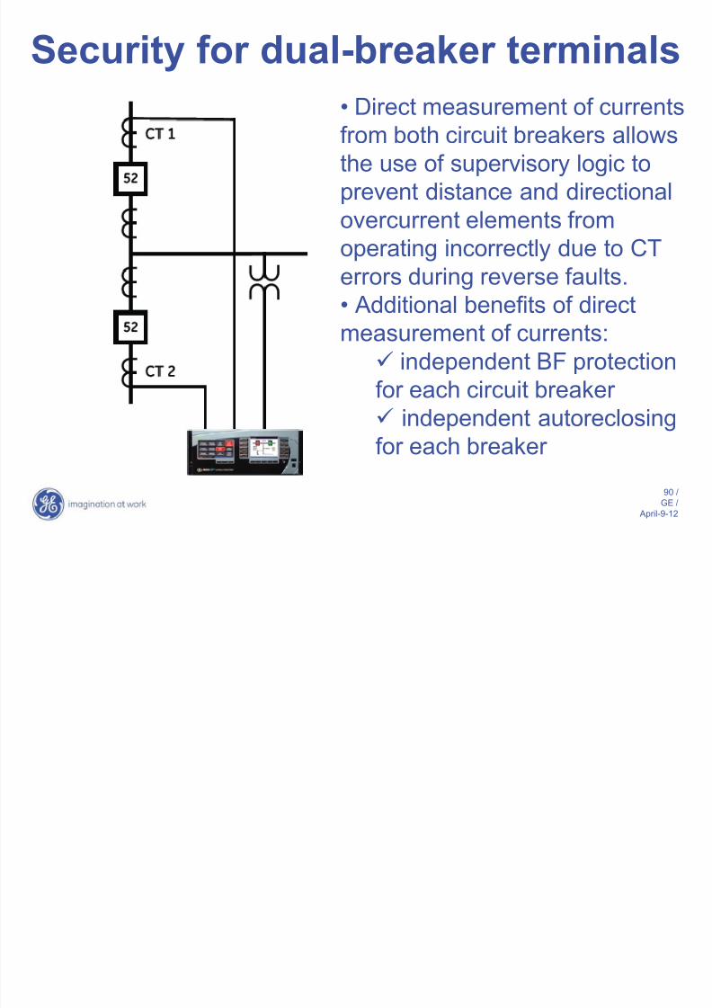
• Direct measurement of currents
from both circuit breakers allowsthe use of supervisory logic to
prevent distance and directional
overcurrent elements from
operating incorrectly due to CT
errors during reverse faults.
• Additional benefits of direct
measurement of currents:
independent BF protection
for each circuit breaker independent autoreclosing
for each breaker
Security for dual-breaker terminals
8/14/2019 88665474 Transmission Line Protection
http://slidepdf.com/reader/full/88665474-transmission-line-protection 91/111
91 /
GE /
April-9-12
Security for dual breaker terminalsSupervisory logic should:
– not affect speed or sensitivity of protection elements – correctly allow tripping during evolving external-to-
internal fault conditions
– determine direction of current flow through eachbreaker independently:
• Both currents in FWD direction internal fault
• One current FWD, one current REV external fault
– allow tripping during all forward/internal faults
– block tripping during all reverse/external faults
– initially block tripping during evolving external-to-internal faults until second fault appears in forwarddirection. Block is then lifted to permit tripping.
Single-pole Tripping

8/14/2019 88665474 Transmission Line Protection
http://slidepdf.com/reader/full/88665474-transmission-line-protection 92/111
92 /
GE /
April-9-12
Single pole Tripping
• Distance relay must correctly identify a SLG
fault and trip only the circuit breaker pole for
the faulted phase.
• Autoreclosing and breaker failure functions
must be initiated correctly on the fault event
• Security must be maintained on the healthy
phases during the open pole condition and anyreclosing attempt.
Out-of-Step Condition
8/14/2019 88665474 Transmission Line Protection
http://slidepdf.com/reader/full/88665474-transmission-line-protection 93/111
93 /
GE /
April-9-12
Out of Step Condition
• For certain operating conditions, a severe
system disturbance can cause system
instability and result in loss of synchronism
between different generating units on aninterconnected system.
Out-of-Step Relaying
8/14/2019 88665474 Transmission Line Protection
http://slidepdf.com/reader/full/88665474-transmission-line-protection 94/111
94 /
GE /
April-9-12
Out of Step Relaying
Out-of-step blocking relays
– Operate in conjunction with mho tripping relaysto prevent a terminal from tripping during severesystem swings & out-of-step conditions.
– Prevent system from separating in an
indiscriminate manner.
Out-of-step tripping relays
– Operate independently of other devices to
detect out-of-step condition during the first poleslip.
– Initiate tripping of breakers that separate systemin order to balance load with available
generation on any isolated part of the system.
Out-of-Step Tripping

8/14/2019 88665474 Transmission Line Protection
http://slidepdf.com/reader/full/88665474-transmission-line-protection 95/111
95 /
GE /
April-9-12
Out of Step TrippingThe locus must stay
for some time
between the outer
and middle
characteristics
Must move and stay
between the middle
and inner
characteristics
When the inner
characteristic is
entered the elementis ready to trip
Power Swing Blocking

8/14/2019 88665474 Transmission Line Protection
http://slidepdf.com/reader/full/88665474-transmission-line-protection 96/111
96 /
GE /
April-9-12
Power Swing Blocking
Applications:
> Establish a blocking signal for stable power swings (PowerSwing Blocking)
> Establish a tripping signal for unstable power swings (Out-
of-Step Tripping)
Responds to:> Positive-sequence voltage and current
Series-compensated lines
8/14/2019 88665474 Transmission Line Protection
http://slidepdf.com/reader/full/88665474-transmission-line-protection 97/111
97 /
GE /
April-9-12
Series compensated lines
EXs SC
XL Infinte
Bus
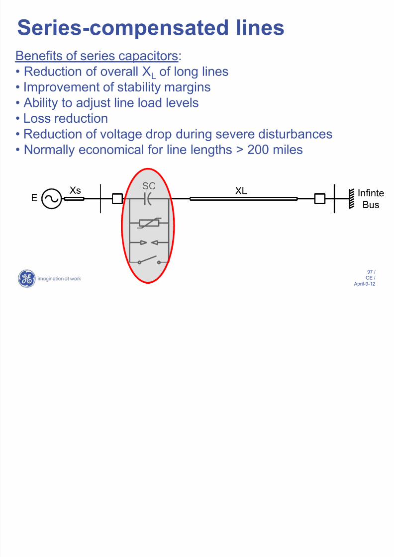
Benefits of series capacitors:
• Reduction of overall XL of long lines• Improvement of stability margins
• Ability to adjust line load levels
• Loss reduction
• Reduction of voltage drop during severe disturbances
• Normally economical for line lengths > 200 miles
Series-compensated lines
8/14/2019 88665474 Transmission Line Protection
http://slidepdf.com/reader/full/88665474-transmission-line-protection 98/111
98 /
GE /
April-9-12
p
EXs SC
XL Infinte
Bus
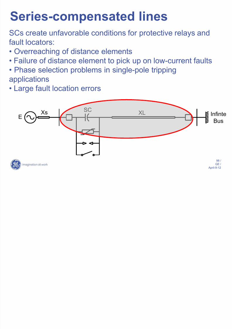
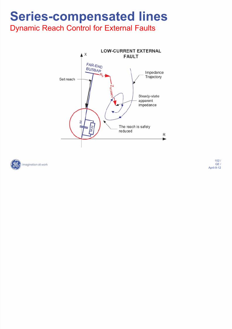
SCs create unfavorable conditions for protective relays and
fault locators:• Overreaching of distance elements
• Failure of distance element to pick up on low-current faults
• Phase selection problems in single-pole tripping
applications
• Large fault location errors
Series-compensated lines

8/14/2019 88665474 Transmission Line Protection
http://slidepdf.com/reader/full/88665474-transmission-line-protection 99/111
99 /
GE /
April-9-12
pSeries Capacitor with MOV
Series-compensated lines

8/14/2019 88665474 Transmission Line Protection
http://slidepdf.com/reader/full/88665474-transmission-line-protection 100/111
100 /
GE /
April-9-12
p
Series-compensated lines

8/14/2019 88665474 Transmission Line Protection
http://slidepdf.com/reader/full/88665474-transmission-line-protection 101/111
101 /
GE /
April-9-12
pDynamic Reach Control
Series-compensated lines
8/14/2019 88665474 Transmission Line Protection
http://slidepdf.com/reader/full/88665474-transmission-line-protection 102/111
102 /
GE /
April-9-12
pDynamic Reach Control for External Faults
Series-compensated lines

8/14/2019 88665474 Transmission Line Protection
http://slidepdf.com/reader/full/88665474-transmission-line-protection 103/111
103 /
GE /
April-9-12
pDynamic Reach Control for External Faults
Series-compensated lines

8/14/2019 88665474 Transmission Line Protection
http://slidepdf.com/reader/full/88665474-transmission-line-protection 104/111
104 /
GE /
April-9-12
pDynamic Reach Control for Internal Faults
Distance Protection Looking

8/14/2019 88665474 Transmission Line Protection
http://slidepdf.com/reader/full/88665474-transmission-line-protection 105/111
105 /
GE /
April-9-12
gThrough a Transformer
• Phase distance elements can be set to see beyond
any 3-phase power transformer
• CTs & VTs may be located independently on
different sides of the transformer• Given distance zone is defined by VT location (not
CTs)
• Reach setting is in sec, and must take into
account location & ratios of VTs, CTs and voltage
ratio of the involved power transformer
Transformer Group Compensation

8/14/2019 88665474 Transmission Line Protection
http://slidepdf.com/reader/full/88665474-transmission-line-protection 106/111
106 /
GE /
April-9-12
p p
Depending on locat ion o f VTs and CTs, distance relays need to
compensate for the phase shi f t and magni tude change caused by the
power transformer
Setting Rules
8/14/2019 88665474 Transmission Line Protection
http://slidepdf.com/reader/full/88665474-transmission-line-protection 107/111
107 /
GE /
April-9-12
g
• Transformer positive sequence impedance must beincluded in reach setting only if transformer liesbetween VTs and intended reach point
• Currents require compensation only if transformer
located between CTs and intended reach point• Voltages require compensation only if transformerlocated between VTs and intended reach point
• Compensation set based on transformer connection
& vector group as seen from CTs/VTs toward reachpoint
Distance Relay Desirable

8/14/2019 88665474 Transmission Line Protection
http://slidepdf.com/reader/full/88665474-transmission-line-protection 108/111
108 /
GE /
April-9-12
> Multiple reversible distance zones
> Individual per-zone, per-element characteristic: – Dynamic voltage memory polarization
– Various characteristics, including mho, quad,lenticular
> Individual per-zone, per-element current supervision(FD)
> Multi-input phase comparator:
– additional ground directional supervision
– dynamic reactance supervision
> Transient overreach filtering/control
> Phase shift & magnitude compensation for distanceapplications with power transformers
yAttributes
Distance Relay Desirable

8/14/2019 88665474 Transmission Line Protection
http://slidepdf.com/reader/full/88665474-transmission-line-protection 109/111
109 /
GE /
April-9-12
> For improved flexibility, it is desirable to have the following
parameters settable on a per zone basis: – Zero-sequence compensation
– Mutual zero-sequence compensation
– Maximum torque angle
– Blinders
– Directional angle
– Comparator limit angles (for lenticular characteristic)
– Overcurrent supervision
yAttributes
Distance Relay Desirable

8/14/2019 88665474 Transmission Line Protection
http://slidepdf.com/reader/full/88665474-transmission-line-protection 110/111
110 /
GE /
April-9-12
> Additional functions
– Overcurrent elements (phase, neutral, ground,directional, negative sequence, etc.)
– Breaker failure
– Automatic reclosing (single & three-pole)
– Sync check – Under/over voltage elements
> Special functions
– Power swing detection
– Load encroachment – Pilot schemes
Attributes

8/14/2019 88665474 Transmission Line Protection
http://slidepdf.com/reader/full/88665474-transmission-line-protection 111/111


