55
Touareg Electronic Diesel Control EDC 16 Design and Function Self-Study Program Course Number 89P303
| Date post: | 04-Jan-2016 |
| Category: |
Documents |
| Upload: | eduardorojas007 |
| View: | 325 times |
| Download: | 7 times |
Touareg Electronic Diesel Control EDC 16Design and Function
Volkswagen of America, Inc.3800 Hamlin RoadAuburn Hills, MI 48326Printed in U.S.A.March 2004
Self-Study ProgramCourse Number 89P303
Volkswagen of America, Inc.Service TrainingPrinted in U.S.A.Printed 03/2004Course Number 89P303
©2004 Volkswagen of America, Inc.
All rights reserved. All information containedin this manual is based on the latestinformation available at the time of printingand is subject to the copyright and otherintellectual property rights of Volkswagen ofAmerica, Inc., its affiliated companies and itslicensors. All rights are reserved to makechanges at any time without notice. No partof this document may be reproduced,stored in a retrieval system, or transmittedin any form or by any means, electronic,mechanical, photocopying, recording orotherwise, nor may these materials bemodified or reposted to other sites withoutthe prior expressed written permission ofthe publisher.
All requests for permission to copy andredistribute information should be referredto Volkswagen of America, Inc.
Always check Technical Bulletins and theVolkswagen Worldwide Repair InformationSystem for information that may supersedeany information included in this booklet.
Trademarks: All brand names and productnames used in this manual are trade names,service marks, trademarks, or registeredtrademarks; and are the property of theirrespective owners.
i
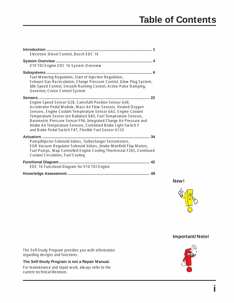
Table of Contents
The Self-Study Program provides you with informationregarding designs and functions.
The Self-Study Program is not a Repair Manual.
For maintenance and repair work, always refer to thecurrent technical literature.
Important/Note!
New!
Introduction ................................................................................................... 1
Electronic Diesel Control, Bosch EDC 16
System Overview .......................................................................................... 4
V10 TDI Engine EDC 16 System Overview
Subsystems ................................................................................................... 6
Fuel Metering Regulation, Start of Injection Regulation,Exhaust Gas Recirculation, Charge Pressure Control, Glow Plug System,Idle Speed Control, Smooth Running Control, Active Pulse Damping,Governor, Cruise Control System
Sensors ........................................................................................................ 22
Engine Speed Sensor G28, Camshaft Position Sensor G40,Accelerator Pedal Module, Mass Air Flow Sensors, Heated OxygenSensors, Engine Coolant Temperature Sensor G62, Engine CoolantTemperature Sensor (on Radiator) G83, Fuel Temperature Sensors,Barometric Pressure Sensor F96, Integrated Charge Air Pressure andIntake Air Temperature Sensors, Combined Brake Light Switch Fand Brake Pedal Switch F47, Flexible Fuel Sensor G133
Actuators ..................................................................................................... 34
Pump/Injector Solenoid Valves, Turbocharger Servomotors,EGR Vacuum Regulator Solenoid Valves, Intake Manifold Flap Motors,Fuel Pumps, Map Controlled Engine Cooling Thermostat F265, ContinuedCoolant Circulation, Fuel Cooling
Functional Diagram..................................................................................... 42
EDC 16 Functional Diagram for V10 TDI Engine
Knowledge Assessment ............................................................................. 49


Introduction
1
Electronic Diesel Control
Greater complexity in the hardware andsoftware for diesel engine managementsystems is necessary to meet theincreasing demand for improvementsin comfort and driveability characteristics,and to reduce fuel consumption andexhaust emissions.
With the advent of electronic diesel controlEDC 16, an engine management system isavailable to meet this demand. This has
been achieved by improving engine controlmodule processing performance and usinga new signal processing system.
This Self-Study Programintroduces the EDC 16 enginemanagement system usingthe V10 TDI engine of theTouareg.
SSP304/301

Introduction
2
Bosch EDC 16
Bosch EDC 16 is a torque-orientatedengine management system. As is thecase with gasoline engines, in the EDC 16system all torque demands are evaluatedby the engine control modules.
This enhances adaptability between vehiclesystems such as the engine managementsystem, brake system, automatictransmission control system, and airconditioning system.
SSP304/062
Internal Torque Demands
• Start• Idle Speed Control• Full Throttle• Power Limitation• Speed Governor• Driving Comfort• Component Protection
Engine Control Module 1 J623
External torque demands
Turbocharger 2 Servomotor V281
Turbocharger 1 Servomotor V280
Valve for Pump/Injector, Cylinder 1 N240Valve for Pump/Injector, Cylinder 2 N241Valve for Pump/Injector, Cylinder 3 N242Valve for Pump/Injector, Cylinder 4 N243Valve for Pump/Injector, Cylinder 5 N244
EGR Vacuum RegulatorSolenoid Valve N18
Realization of torque demands
Climatronic Control Module J255
ABS Control Module withEDL/ASR/ESP J104
TransmissionControl Module J217
Cruise Control System
Accelerator Pedal Module

3
The Bosch EDC 16 engine managementsystem is designed for use in bothsingle and dual engine control moduleconfigurations. The configuration useddepends on the number of cylindersin the engine.
On the V10 TDI engine, Engine ControlModule 1 J623 fulfills the basic functionsfor cylinder bank I and Engine ControlModule 2 J624 for cylinder bank II. Basicfunctions are, for example, actuation of thesolenoid valves for pump/injectors andexhaust gas recirculation.
Some of the functions that cover bothcylinder banks, such as the coolant supply,are carried out by Engine Control Module 1J623; others, like the smooth runningcontrol by Engine Control Module 2 J624.
Information received by Engine ControlModule 1 J623 is sent to Engine ControlModule 2 J624 via an internal CAN data bus.
Introduction
After encoding, the enginecontrol modules can no longerbe interchanged.
Engine Control Modules in
the Drivetrain CAN Data Bus
Both engine control modules are identical.
The differentiation between Engine ControlModule 1 J623 and Engine Control Module 2J624 is made by a coding link in theconnector for Engine Control Module 2 J624.
Engine ControlModule 1 J623
SSP304/071
SSP304/026
Control Modulewith IndicatorUnit in InstrumentPanel Insert J285
AirbagControl ModuleJ234
Turbocharger 2ServomotorV281
Steering ColumnElectronicSystems ControlModule J527
Engine ControlModule 2J624
Access/StartControl ModuleJ518
TransmissionControl ModuleJ217
Turbocharger 1ServomotorV280
ABS ControlModule withEDL/ASR/ESPJ104
Engine ControlModule 1J623
Engine ControlModule 2 J624
Inte
rnal
CA
N D
ata
Bus

System Overview
4
V10 TDI Engine EDC 16System Overview
Sensors
Engine Speed Sensor G28
Additional Input Signals
Flexible Fuel Sensor G133
Brake Light Switch FBrake Pedal Switch F47
Charge Air Pressure Sensor G31Intake Air Temperature Sensor G42
Fuel Temperature Sensor G81
Engine Coolant Temperature Sensor(on Radiator) G83
Heated Oxygen Sensor G39
Mass Air Flow Sensor G70
Throttle Position Sensor G79Kick Down Switch F8Closed Throttle Position Switch F60
Engine Coolant Temperature Sensor C62

System Overview
Glow Plug Relay 2 J495Glow Plug 6 Q15Glow Plug 7 Q16Glow Plug 8 Q17Glow Plug 9 Q18Glow Plug 10 Q19
Oxygen Sensor Heater 2 Z28
Intake Flap Motor 2 V275
Valve 2 for EGR N213
Valve for Pump/Injector, Cylinder 6 N245Valve for Pump/Injector, Cylinder 7 N303Valve for Pump/Injector, Cylinder 8 N304Valve for Pump/Injector, Cylinder 9 N305Valve for Pump/Injector, Cylinder 10 N306
5
Turbocharger 2Servomotor V281
ABS Control Module withEDL/ASR/ESP J104Transmission Control Module J217Control Module with Indicator Unitin Instrument Panel Insert J285Airbag Control Module J234
Eng
ine
Spe
ed
Camshaft PositionSensor G40
Barometric PressureSensor F96
Engine ControlModule 2 J624
16-Pin Connector(DiagnosisConnection) T16
Engine ControlModule 1 J623
Fuel TemperatureSensor 2 G248
Intake Air TemperatureSensor 2 G299Charge Air PressureSensor 2 G447
Heated OxygenSensor 2 G108
Mass Air FlowSensor 2 G246
Turbocharger 1Servomotor V280 EGR Vacuum Regulator Solenoid Valve N18
Actuators
Valve for Pump/Injector, Cylinder 1 N240Valve for Pump/Injector, Cylinder 2 N241Valve for Pump/Injector, Cylinder 3 N242Valve for Pump/Injector, Cylinder 4 N243Valve for Pump/Injector, Cylinder 5 N244
SSP304/003Additional Output Signals
Glow Plug Relay J52Glow Plug 1 Q10Glow Plug 2 Q11Glow Plug 3 Q12Glow Plug 4 Q13Glow Plug 5 Q14
Oxygen Sensor Heater Z19
Relay for Pump, Fuel Cooling J445Pump for Fuel Cooler V166
Auxiliary Engine Coolant Pump Relay J496After-Run Coolant Pump V51
Map Controlled Engine Cooling Thermostat F265
Fuel Pump Relay J17Fuel Pump G6Transfer Fuel Pump G23
Motor for Intake Flap V157

6
Subsystems
The illustrations in the subsystemexamples show cylinder bank I ofthe V10 TDI engine.
Subsystem operation is similarfor cylinder bank II as well.
Only components relevant to thesubsystems are called out.
Fuel Metering Regulation
The quantity of fuel injected into thecylinders influences such engine propertiesas torque, power output, fuel consumption,exhaust gas emissions, and mechanicaland thermal stress.
Fuel metering regulation enablesoptimal fuel combustion under all engineoperating conditions.
Subsystem Operation
The specified torque is calculated from theinternal and external torque demands.
To reach the required torque specificationfor this engine, a set quantity of fuel isrequired.
Example
The quantity of fuel is calculated by theengine control module based upon thefollowing inputs:
• Driver requirements• Engine speed• Amount of air drawn• Coolant temperature• Fuel temperature• Intake air temperature
To protect the engine against mechanicaldamage and to prevent black smoke,there must be limitations on the quantityof fuel injected.
For this reason, the engine control modulecalculates a limit value for this quantity.
The fuel quantity limit value depends onthe following inputs:
• Engine speed• Air mass• Air pressure

M
7
Subsystems
F8 Kick Down SwitchF60 Closed Throttle Position SwitchF96 Barometric Pressure Sensor
G28 Engine Speed SensorG42 Intake Air Temperature SensorG62 Engine Coolant Temperature SensorG70 Mass Air Flow SensorG79 Throttle Position SensorG81 Fuel Temperature Sensor
J623 Engine Control Module 1 (Cylinder Bank I)J624 Engine Control Module 2 (Cylinder Bank II)
N240, N241, N242, N243, N244Valves for Pump/Injectors, Cylinders 1through 5 (Cylinder Bank I)
SSP304/079
Air Intake, Normal
Air Intake, Compressed
Exhaust Gas
Input Signal
Output Signal
Drivetrain CAN Data Bus
F96
G79F8F60J623J624
G28
G81
G62
N240,N241,N242,N243,N244
G70
G42

Subsystems
8
Start of Injection Regulation
The start of injection regulation influences anumber of engine properties, includingengine performance, fuel consumption,noise levels, and exhaust emissions.
Start of injection regulation determines thecorrect timing for fuel delivery and injectionat each cylinder.
Subsystem Operation
The engine control module calculates thestart of injection from:
• Engine speed
• Calculated quantity of fuel to be injectedfrom the fuel metering regulation.
Additional influencing factors include:
• Coolant temperature
• Air pressure
The engine control module monitors theelectrical current that actuates the solenoidvalves at the pump/injectors.
This provides feedback to the engine controlmodule of the actual point in time wheninjection begins.
The engine control module uses thisfeedback to regulate the beginning ofinjection periods (BIP) during subsequentcombustion cycles and to detectmalfunctions of the pump/injectorsolenoid valves.
SSP304/073
M
t
I M
BIP
F96 Barometric Pressure Sensor
G28 Engine Speed SensorG42 Intake Air Temperature SensorG62 Engine Coolant Temperature Sensor
J623 Engine Control Module 1J624 Engine Control Module 2
N240, N241, N242, N243, N244Valves for Pump/Injectors, Cylinders 1through 5 (Cylinder Bank I)
Air Intake, Normal
Air Intake, Compressed
Exhaust Gas
Input Signal
Output Signal
Drivetrain CAN Data Bus
J624
G28
G62
N240, N241,N242, N243,N244
G42
F96
J623

9
Current Pattern — Pump/Injector Solenoid Valve
Subsystems
IM – Solenoid Valve Actuating Currentt – TimeBIP – Beginning of Injection Period (Valve Closes)
SSP304/072
Start of injection is initiated when thepump/injector solenoid valve is actuated.
Actuating current applied to a pump/injectorsolenoid valve creates a magnetic field. Asthe applied current intensity increases, thevalve closes; the magnetic coil presses thesolenoid valve needle into its valve seat. Thiscloses off the path from the fuel supply lineto the pump/injector high-pressure chamberand the injection period begins.
As the solenoid valve needle contacts itsvalve seat, the distinctive signature of analternately dropping and rising current flowis detected by the engine control module.This point is called the beginning of injectionperiod (BIP). It indicates the completeclosure of the pump/injector solenoid valveand the starting point of fuel delivery.
“Start of injection”
is the point in time when theactuating current to the pump/injector solenoid valve is initiated.
”Beginning of
injection period (BIP)”
is the point in time when thesolenoid valve needle contactsthe valve seat.
With the solenoid valve closed, a holdingcurrent is maintained at a constant levelby the engine control module to keep itclosed. Once the required time period forfuel delivery has elapsed, the actuatingcurrent is switched off and the solenoidvalve opens.
The actual moment at which the pump/injector solenoid valve closes (BIP) isused by the engine control module tocalculate the point of actuation for thenext injection period.
If the actual BIP deviates from the mappeddetails stored in the engine control module,the engine control module will correct thepoint of valve actuation (start of injection)for the next combustion cycle.
To detect pump/injector solenoid valvefaults, the engine control module evaluatesthe BIP position from the current flowpattern. If there are no faults, BIP will bewithin the control limit. If this is not thecase, the valve is faulty.
Effects of failure
If a fault is detected at the solenoid valve,start of injection is determined based onfixed values from the control map.Regulation is no longer possible andperformance is impaired.
IM
PickupCurrent
Control Limit
Holding Current
t
BIP
End of ValveActuation
Start of ValveActuation(Start of Injection)

10
Subsystems
Exhaust Gas Recirculation
When exhaust gas recirculation (EGR)occurs, some of the exhaust emissionsfrom the combustion process are usedagain. Because the exhaust gases containvery little oxygen, the peak combustiontemperature is lowered and nitrogen oxideemissions (NOX) are reduced. Exhaust gasrecirculation occurs up to an engine speedof approximately 3000 rpm.
Subsystem Operation
The amount of recirculated exhaust gasdepends on the engine speed, the amountof fuel injected, the amount of air drawnin, the intake air temperature, and theair pressure.
Heated oxygen sensor control
for exhaust gas recirculation
On the V10 TDI engine, the amount ofrecirculated exhaust gas is determined andcorrected by oxygen sensor control. Withthis system, the oxygen content in theexhaust gas is constantly monitored and asensor signal is sent to the engine controlmodule.
If the actual oxygen content deviatesfrom the specification requirements in thecontrol map, the engine control moduleactuates the EGR Vacuum RegulatorSolenoid Valve N18 and increases ordecreases the amount of recirculatedexhaust gas. With oxygen sensor control,the amount of recirculated exhaust gas canbe determined precisely.
• If the oxygen content is too high,the amount of recirculated exhaust gasis increased.
• If the oxygen content is too low, theamount of recirculated exhaust gasis lowered.

11
Subsystems
SSP304/044
M
F96 Barometric Pressure SensorG28 Engine Speed SensorG39 Heated Oxygen SensorG62 Engine Coolant Temperature SensorG70 Mass Air Flow SensorJ623 Engine Control Module 1J624 Engine Control Module 2N18 EGR Vacuum Regulator Solenoid ValveN240, N241, N242, N243, N244
Valves for Pump/Injectors, Cylinders 1through 5 (Cylinder Bank I)
V157 Motor for Intake Flap
A Intake Manifold FlapB EGR ValveC Catalytic ConverterD Vacuum PumpE Charged Air Cooler
Air Intake, Normal
Air Intake, Compressed
Exhaust Gas
Coolant
Vacuum
Input Signal
Output Signal
Drivetrain CAN Data Bus
G39G28
G62
N240, N241,N242, N243, N244
ED
C
B A
G70V157
N18J623J624
F96

12
Charge Pressure Control
The charge pressure is controlled by a mapthat is stored in the engine control module.
Subsystem Operation
The engine control module sends a signalvia the drivetrain CAN data bus to theturbocharger servomotors.
The signal generated by the engine controlmodule determines a turbocharger vanesetting value between 0% and 100%.
The turbocharger servomotors adjust theangles of the turbocharger vanes asinstructed, which results in a correspondingadjustment in turbocharger impeller speed.
Subsystems
The charge pressure is increased orreduced accordingly.
Charge pressure control depends on thedemand for torque.
To control the charge pressure, signals fromthe charge air pressure sensors are used.The signals from the intake air temperaturesensors, Engine Coolant TemperatureSensor G62 and Barometric Pressure SensorF96, are used as correction factors.
The charge pressure is reduced graduallywhen the vehicle is travelling at highaltitudes to protect the turbocharger.

13
Subsystems
M
Air Intake, Normal
Air Intake, Compressed
Exhaust Gas
Input Signal
Output Signal
Drivetrain CAN Data Bus
SSP304/045
F96 Barometric Pressure Sensor
G31 Charge Air Pressure SensorG42 Intake Air Temperature SensorG62 Engine Coolant Temperature SensorG70 Mass Air Flow Sensor
J623 Engine Control Module 1J624 Engine Control Module 2
N240, N241, N242, N243, N244Valves for Pump/Injectors, Cylinders 1through 5 (Cylinder Bank I)
V280 Turbocharger 1 Servomotor
A Charged Air Cooler
B Turbocharger
V280
G62
N240, N241, N242,N243, N244
B
A
G70G31G42
J623J624
F96

14
Glow Plug System
The glow plug system makes it easierto start the engine at low outsidetemperatures. The system is controlled bythe engine control module at coolanttemperatures below 48°F (9°C).
The glow plug relays are actuated by theengine control module. Once actuatedthey distribute the current required for theglow plugs.
Glow Period
The glow plugs are activated when theignition is switched on and outsidetemperature is below 48°F (9°C). The GlowPlug Indicator Light K29 will light up.
When the glow plug period has elapsed,the Glow Plug Indicator Light K29 will goout and the engine can be started.
Subsystems
Extended Glow Period
Once the engine starts, there is anextended glow period. This helps to lowerthe combustion noise. It also improvesthe idle speed quality and the carbondioxide emissions are reduced.
The extended glow period lasts fora maximum of four minutes and isdeactivated at engine speeds above2500 rpm.
There is no extended glow period if thebattery voltage is too low to support it.

15
Subsystems
SSP304/043
Driv
etra
in C
AN
Dat
a B
us
Glow Plug IndicatorLight K29
Glow Plug Relay 2 J495Glow Plug 6 Q15Glow Plug 7 Q16Glow Plug 8 Q17Glow Plug 9 Q18Glow Plug 10 Q19
Glow Plug Relay J52Glow Plug 1 Q10Glow Plug 2 Q11Glow Plug 3 Q12Glow Plug 4 Q13Glow Plug 5 Q14
Engine ControlModule 1 J623
Engine ControlModule 2 J624
Engine CoolantTemperatureSensor G62
Engine SpeedSensor G28

16
Subsystems
Idle Speed Control
Idle speed control sets a predeterminedengine idle speed depending upon theoperating conditions. For example, a coldengine will have a higher idle speed than awarm engine.
Additional performance demands are alsoconsidered, such as:
• Electrical system requirements at lowengine speeds.
• Power steering pump operation.
• The high pressures required fordiesel injection.
• The energy required to overcome theinternal friction of the engine.
• Torque converter operation atdifferent loads.
Subsystem Operation
The specified engine idle speedis regulated by a map in the enginecontrol module.
The map draws on information from:
• Engine Coolant Temperature Sensor G62.
• Load on the generator.
• Load on the vehicle electrical system.
The engine control module continuallyadapts the amount of fuel injected until theactual engine idle speed matches thespecified value.
To avoid unnecessary emissions, the idlespeed is kept to a minimum level, thoughduring this process, demands on smoothrunning also play a role.

17
Subsystems
SSP304/074
Engine ControlModule 1 J623
Valves for Pump/Injectors,Cylinders 1 through 5N240, N241, N242, N243, N244(Cylinder Bank I)
Valves for Pump/Injectors,Cylinders 6 through 10N245, N303, N304, N305, N306(Cylinder Bank II)
Engine ControlModule 2 J624
AdditionalRequirements
Generator Load(DFM Signal)
Engine CoolantTemperatureSensor G62
Engine SpeedSensor G28
Throttle PositionSensor G79Closed ThrottlePosition Switch F60

+
=
+
+
=
+
590
550
580
540
600
J623
J624
600
580
530
590
540
18
Smooth Running Control
Smooth running control improves enginerunning at idle speed.
Different cylinders in an engine can oftengenerate different levels of torque eventhough the same amount of fuel has beeninjected.
Possible causes of this include differencesin any combination of the following:
• Tolerances of the parts.• Cylinder compression.• Friction in the cylinders.• Hydraulic injector components.
The effects of these differences intorque include:
• Unbalanced engine running.• Increased exhaust gas emissions.
The smooth running control is designed todetect the pulses in speed that are causedas a result. The pulses in speed are then
Subsystems
balanced by targeted control of the amountinjected at the affected cylinders.
Subsystem Operation
Detection works at idle speed using asignal from the Engine Speed Sensor G28.
If the signals are received in a balancedrhythm, the cylinders are all working thesame way.
If the performance of one cylinder isslower than the others, the crankshaftwill need more time to reach the nextpoint of ignition.
A cylinder that performs faster than theothers will need less time than the othersto reach the next point of ignition.
If the Engine Control Module 2 J624detects a deviation, the affected cylinderwill receive a smaller or greater amount offuel until the engine runs smoothly again.
Example: Necessary changes in the amount
of fuel injected at specified speeds of 580 rpm.
SSP304/058Change in Quantity of Fuel InjectedActual Speed

0.0007 (12)
0.0012 (20)
0.0015 (25)
Fu
el Q
uan
tity
In
jecte
d
800
1000
En
gin
e S
peed
(rp
m)
0 1 2
Time (Seconds)
in3 (mm3)
0.0007 (12)
0.0012 (20)
0.0015 (25)
Fu
el Q
uan
tity
In
jecte
d
800
1000
En
gin
e S
peed
(rp
m)
0 1 2
Time (Seconds)
in3 (mm3)
19
Active Pulse Damping
The active pulse damping systemreduces the jerking movements that canbe generated by engine load changesunder acceleration.
Without Active Pulse DampingWithout active pulse damping, when theaccelerator pedal is pressed, a largeamount of fuel (blue curve) is injected fora brief period.
This sudden load change can lead topulsations (red curve) in the vehicledrivetrain due to changes in engine torque.
These pulsations are perceived by thevehicle occupants as jerking movements.
With Active Pulse Damping
With active pulse damping, when theaccelerator pedal is pressed, the amount offuel injected (blue curve) is not the fullamount demanded at the start by theaccelerator pedal position.
Instead, injected fuel is reduced by abouthalf and gradually increased over the firstsecond or so of acceleration.
If there are pulsations in the vehicledrivetrain during that time, they are detectedby evaluation of the engine speed signal.
When engine speed increases, the amountof fuel injected is reduced.
When engine speed decreases, fuelinjected is increased.
These damped pulsations (red curve)are less noticeable by the occupants ofthe vehicle.
Subsystems
Without Active Pulse Damping
With Active Pulse Damping
SSP304/054
SSP304/053

20
Governor
The governor protects the engine fromover-speed damage. The engine isgoverned to a maximum permissiblespeed that cannot be exceeded for longperiods of time.
Subsystem Operation
Engine speed regulation starts just beforemaximum permissible speed is reached.Once regulation starts, the amount of fuelinjected is continually reduced.
Subsystems
Engine SpeedSensor G28
When the maximum permissible enginespeed is reached, the amount of fuelinjected remains constant until the drivingconditions change.
The adaptive function of the governoris kept as smooth as possible to preventsurges in the amount of fuel injectedduring acceleration.
Engine ControlModule 1 J623
Maximum SpeedStart of Regulation
Valves for Pump/Injectors,Cylinders 1 through 5 N240, N241,N242, N243, N244 (Cylinder Bank I)
Valves for Pump/Injectors,Cylinders 6 through 10 N245, N303,N304, N305, N306 (Cylinder Bank II)
SSP304/069
Time (Seconds)
En
gin
e S
peed
(rp
m)
Engine ControlModule 2 J624

21
Cruise Control System
The cruise control system (CCS) allowsthe vehicle to be driven at a constant speedwithout the driver having to press theaccelerator pedal.
Cruise control on the Touareg starts in thereduction gear at 3.7 mph (6 km/h) and innormal operation at 12.4 mph (20 km/h).
Subsystems
Subsystem Operation
The specified speed is set using a button onthe multi-function steering wheel. The signalis sent to Engine Control Module 1 J623 andpassed on to Engine Control Module 2 J624via an internal CAN data bus.
The engine control modules adapt theamount of fuel injected so that the actualspeed is the same as the specified speed.
Engine ControlModule 1 J623
SSP304/066
Valves for Pump/Injectors,Cylinders 1 through 5 N240, N241,N242, N243, N244 (Cylinder Bank I)
ABS Control Modulewith EDL/ASR/ESP J104
Airbag ControlModule J234
Control Module withIndicator Unit in InstrumentPanel Insert J285
Valves for Pump/Injectors,Cylinders 6 through 10 N245,N303, N304, N305, N306(Cylinder Bank II)
Engine ControlModule 2 J624
Multi-FunctionSteering Wheelwith CCS Buttons
Engine SpeedSensor G28
Brake Light Switch FBrake Pedal Switch F47Throttle PositionSensor G79

22
Sensors
Engine Speed Sensor G28
The Engine Speed Sensor G28 is bolted tothe side of the cylinder block. It picks upthe position of the crankshaft by reading areference gap in the spacing of the teethon an engine speed sensor wheel.
Signal Application
The signal from Engine Speed Sensor G28is used to determine the speed of theengine and the precise position of thecrankshaft. With this information, theamount of fuel injected and start ofinjection is calculated.
Effects of failure
In the case of signal loss, the engine willswitch off and cannot be restarted.
The signal from the Engine SpeedSensor G28 is sent directly toEngine Control Module 1 J623.Engine Control Module 2 J624receives the signal indirectly butsimultaneously from EngineControl Module 1 J623 via aseparate wire connection.
Engine SpeedSensor G28
Engine Speed Sensor G28
SSP304/008
SSP304/059Reference Gap
Engine SpeedSensor Wheel

23
Sensors
Camshaft Position Sensor G40
The Camshaft Position Sensor G40 is aHall-effect sensor. It is bolted to thecylinder head of cylinder bank I below themechanical fuel pump.
Camshaft Position Sensor G40 scans thequick-start sender wheel to determine theposition of the camshaft.
Signal Application
Using the Camshaft Position Sensor G40signal, the relative position of the camshaftto the crankshaft is picked up quickly whenthe engine is started.
Together with the signal from the EngineSpeed Sensor G28, the system can detectwhich cylinder is at top-dead-center (TDC).
Effects of failure
If the Camshaft Position Sensor G40 signalfails, the signal from the Engine SpeedSensor G28 is used in its place.
Because the position of the camshaft andthe cylinders cannot be detectedimmediately, starting of the engine couldtake slightly longer than normal.
On the V10 TDI engine, just oneCamshaft Position Sensor G40is installed. The signal is sent toboth engine control modules.
Camshaft PositionSensor G40
Camshaft Position Sensor G40
SSP304/007
Quick-Start Sender Wheel
SSP304/020

24
Accelerator Pedal Module
The Throttle Position Sensor G79, the KickDown Switch F8, and the Closed ThrottlePosition Switch F60 are all incorporated intoa single housing. This accelerator pedalmodule is mounted on the pedal cluster.
Accelerator Pedal Module
Signal Application
Throttle Position Sensor G79
The Throttle Position Sensor G79 detectsthe position of the accelerator pedal acrossits entire range of movement.
It is a main input signal to calculate theamount of fuel to be injected.
Closed Throttle Position Switch F60
The Closed Throttle Position Switch F60detects when there is no pressure on theaccelerator pedal and sends a signal thatinitiates idle speed control.
Kick Down Switch F8
The Kick Down Switch F8 sends amessage to Engine Control Module 1 J623when the accelerator pedal is pressed allthe way to the full extent of its travel.
This information is sent by the EngineControl Module 1 J623 via the drivetrainCAN data bus to the Transmission ControlModule J217 and the kick-down function isactivated.
Effects of failure
If the Throttle Position Sensor G79 signalfails, the position of the accelerator pedalwill no longer be detected.
The engine will only run at increased idlespeed and the Glow Plug Indicator LightK29 will flash.
Sensors
Throttle PositionSensor G79
SSP304/017
SSP304/017a
Closed ThrottlePosition Switch F60
Kick DownSwitch F8

25
Mass Air Flow Sensors
Each cylinder bank has its own hot filmmass air flow sensor with backflowdetection.
• Mass Air Flow Sensor G70 (bank I)
• Mass Air Flow Sensor 2 G246 (bank II)
These sensors are installed in the intakepassages in front of the intake manifoldbridges. They determine the actual air massdrawn in for each cylinder bank.
Sensors
Intake Manifold Bridge
Air Cleaner
Mass Air FlowSensor G70
Mass Air FlowSensor 2 G246
SSP304/060
Signal Application
The signals from the two mass air flowsensors are used by their respective enginecontrol modules to calculate the amount offuel to be injected and the amount ofexhaust gas to be recirculated for eachcylinder bank.
Effects of failure
If the signal from a mass air flow sensorfails, its respective engine control moduleoperates using a predeterminedreplacement value and exhaust gasrecirculation is switched off.

Sensors
Heated Oxygen Sensors
On the V10 TDI engine, broadband heatedoxygen sensors are located in the exhaustsystem in front of the starter catalyst, onefor each cylinder bank.
• Heated Oxygen Sensor G39 (bank I)
• Heated Oxygen Sensor 2 G108 (bank II)
The remaining oxygen content in theexhaust gas is measured by these sensors.
26
Heated OxygenSensor G39
SSP304/033
Heated OxygenSensor 2 G108
Signal Application
Using the signals from both heated oxygensensors, the amount of recirculatedexhaust gas is corrected.
Effects of failure
If the heated oxygen sensor signals fail, theamount of recirculated exhaust gas will bedetermined by the mass air flow sensors.Because this method of regulation is not asprecise, nitrogen oxide emissions levelsmay rise.

Sensors
27
Engine Coolant TemperatureSensor G62
The Engine Coolant Temperature SensorG62 is mounted in the coolant connectingpipe between the cylinder heads. It sendsthe coolant temperature to Engine ControlModule 1 J623.
Signal Application
The coolant temperature is used by theengine control modules as a correctionvalue to calculate such variables as theamount of fuel to be injected, the chargepressure, start of fuel delivery, and theamount of exhaust gas to be recirculated.
Engine CoolantTemperatureSensor G62
SSP304/035
This information is also used to regulate thecoolant temperature depending on theoperating conditions.
Effects of failure
If the Engine Coolant TemperatureSensor G62 signal fails, the Engine ControlModule 1 J623 uses the signals from theEngine Coolant Temperature Sensor (onRadiator) G83 and the Fuel TemperatureSensor G81; Engine Control Module 2 J624uses the signal from Fuel TemperatureSensor 2 G248.
CoolantConnectingPipe

28
Engine Coolant TemperatureSensor (on Radiator) G83
The Engine Coolant Temperature Sensor(on Radiator) G83 measures the coolanttemperature at the radiator outlet.
Signal Application
By comparing signals from both EngineCoolant Temperature Sensor G62 andEngine Coolant Temperature Sensor (onRadiator) G83, the Engine Control Module 1J623 can determine when to actuate theradiator-mounted coolant fans.
Effects of failure
If the signal from Engine CoolantTemperature Sensor (on Radiator) G83fails, coolant fan output stage 1 remainsconstantly active.
Coolant temperature regulation is continued.
Engine Coolant TemperatureSensor (on Radiator) G83
Sensors
SSP304/035
29
Sensors
Fuel Filter Module
SSP304/006
Fuel TemperatureSensor G81
Fuel TemperatureSensor 2 G248
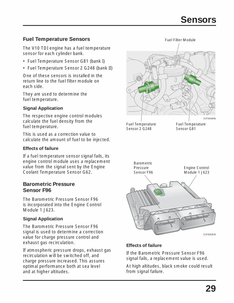
Fuel Temperature Sensors
The V10 TDI engine has a fuel temperaturesensor for each cylinder bank.
• Fuel Temperature Sensor G81 (bank I)• Fuel Temperature Sensor 2 G248 (bank II)
One of these sensors is installed in thereturn line to the fuel filter module oneach side.
They are used to determine thefuel temperature.
Signal Application
The respective engine control modulescalculate the fuel density from thefuel temperature.
This is used as a correction value tocalculate the amount of fuel to be injected.
Effects of failure
If a fuel temperature sensor signal fails, itsengine control module uses a replacementvalue from the signal sent by the EngineCoolant Temperature Sensor G62.
Barometric PressureSensor F96
The Barometric Pressure Sensor F96is incorporated into the Engine ControlModule 1 J623.
Signal Application
The Barometric Pressure Sensor F96signal is used to determine a correctionvalue for charge pressure control andexhaust gas recirculation.
If atmospheric pressure drops, exhaust gasrecirculation will be switched off, andcharge pressure increased. This assuresoptimal performance both at sea leveland at higher altitudes.
BarometricPressureSensor F96
SSP304/039
Engine ControlModule 1 J623
Effects of failure
If the Barometric Pressure Sensor F96signal fails, a replacement value is used.
At high altitudes, black smoke could resultfrom signal failure.

Integrated Charge Air Pressureand Intake Air Temperature Sensors
Charge Air Pressure Sensor G31 and IntakeAir Temperature Sensor G42 are integratedas one component, which is installed in theintake manifold for cylinder bank I.
Charge Air Pressure Sensor 2 G447 andIntake Air Temperature Sensor 2 G299
SSP304/024
30
Sensors
The Charge Air Pressure Sensor 2 G447and Intake Air Temperature Sensor 2 G299are also integrated into a single component,installed in the intake manifold for cylinderbank II.
Charge Air Pressure Sensors
• Charge Air Pressure Sensor G31 (bank I)
• Charge Air Pressure Sensor 2 G447(bank II)
Signal Application
The signals from Charge Air PressureSensor G31 and Charge Air PressureSensor 2 G447 are required to regulate andmonitor the charge air pressure.
The calculated values are compared bytheir respective engine control modules
with the specifications from the chargeair pressure maps.
If the actual values deviate from thespecification, the charge air pressure isaltered accordingly by signals from theEngine Control Module 1 J623 via thedrivetrain CAN data bus to Turbocharger 1Servomotor V280 for cylinder bank I andTurbocharger 2 Servomotor V281 forcylinder bank II.
Effects of failure
If a charge air pressure sensor fails, thecharge air pressure is controlled at anextremely low level to protect the enginefrom damage. Because of this,performance is impaired considerably.
Intake Air Temperature Sensors
• Intake Air Temperature Sensor G42(bank I)
• Intake Air Temperature Sensor 2 G299(bank II)
Signal Application
The signals from Intake Air TemperatureSensor G42 and Intake Air TemperatureSensor 2 G299 are required by theirrespective engine control modules tocalculate a correction value for the chargeair pressure.
When the signal from these senders isevaluated, the influence of the temperatureon the density of the fuel is also considered.
Effects of failure
If an intake air temperature sensor signalfails, the engine control modules will use afixed replacement value. The result couldbe impaired performance.

31
Sensors
SSP304/017b
Brake Light Switch F andBrake Pedal Switch F47
Combined Brake Light Switch Fand Brake Pedal Switch F47
The Brake Light Switch F and Brake PedalSwitch F47 are combined in a singlecomponent mounted on the pedal cluster.Both switches send a signal to EngineControl Module 1 J623 when the brakeis applied.
Signal Application
When the brake is applied, the cruisecontrol system is switched off.
If actuation of the accelerator pedal andthe brake pedal is detected, idle speedis increased.
Effects of failure
If the signal fails from one of these sensors,the amount of fuel injected will be reducedand the engine will have less output.
In addition, the cruise control system willbe switched off.

32
Sensors
Flexible Fuel Sensor G133
The Flexible Fuel Sensor G133 is bolted tothe fuel filter module. Using two sensorcontact pins immersed in the fuel at thebottom of the fuel filter module, it monitorsthe composition of the fuel to detectexcessive water levels and sends acorresponding signal to Engine ControlModule 1 J623.
Signal Application
If the signal from Flexible Fuel Sensor G133indicates too much water is present in thefuel filter module, the Glow Plug IndicatorLight K29 flashes on and off to alert theoperator to shut down the engine as soonas possible to prevent water from enteringthe fuel injection system.
Water in the systemcould result incorrosion damage.
Fuel Filter Module
Drainage Connection forContaminated Fuel Removal
SSP304/082
SSP304/047
Fuel FilterModule
Flexible FuelSensor G133

33
Sensors
Sensor Operation
A constant voltage is applied to FlexibleFuel Sensor G133 by Engine ControlModule 1 J623.
With acceptable water level
When the water level in the fuel filtermodule is low, the Flexible Fuel SensorG133 contact pins are surrounded bydiesel fuel.
Because diesel fuel has a relativelylow level of conductivity, there is a highsignal response.
This signal indicates to the Engine ControlModule 1 J623 that the water level iswithin acceptable limits.
The Engine Control Module 1 J623 sendsthis information to the instrument cluster.
The Glow Plug Indicator Light K29 does notlight up.
With water level too high
When the water level is too high, thecontact pins are surrounded by water.
Because water has a high level ofconductivity, there is a low signal response.
This signal indicates to the Engine ControlModule 1 J623 that the water level is toohigh and sends the information to theinstrument cluster.
The Glow Plug Indicator Light K29 willflash. This flashing light indicates a fault inthe engine management system.
Contact Pins
450
V
450
V
SSP304/050Water
Fuel
Contact Pins
SSP304/055Water
Fuel
With Acceptable Water Level
Positive
Ground
Input Signal
Drivetrain CAN Data Bus
With Water Level Too High

34
Pump/Injector Solenoid Valves
There is one pump/injector for eachcylinder. The pump/injector solenoid valvesare secured to the pump/injector bodies byunion nuts.
• Valves for Pump/Injectors, Cylinders 1through 5 N240, N241, N242, N243,N244 for cylinder bank I.
• Valves for Pump/Injectors, Cylinders 6through 10 N245, N303, N304, N305,N306 for cylinder bank II.
These solenoid valves are actuated by theirrespective engine control modules, whichcontrol start of fuel delivery and the amountof fuel injected.
Function
As soon as a pump/injector solenoid valveis actuated by its engine control module,the valve needle is pushed onto its seat bythe magnetic coil. This closes the path offuel to the compression chamber of thepump/injector and injection starts.
The amount of fuel injected is determinedby the length of time that the solenoid valveis actuated. As long as the pump/injectorsolenoid valve is closed, fuel is injected intothe combustion chamber.
Effects of failure
If a pump/injector solenoid valve fails, theengine will not run smoothly. Performancewill be impaired.
If the valve stays open, pressure cannotbe built up in the pump/injector. If the valvestays closed, the pump/injector compressionchamber cannot be filled. In either case, fuelcannot be injected into the cylinder.
TypicalPump/InjectorSolenoid Valve
Typical Pump/InjectorSolenoid Valve
SSP304/032
SSP304/022
Actuators

35
Actuators
Turbocharger 2Servomotor V281
Turbocharger Servomotors
The turbocharger servomotors arepositioning motors for the turbochargervanes. They are bolted to brackets beneaththeir respective turbochargers.
• Turbocharger 1 Servomotor V280
• Turbocharger 2 Servomotor V281
Each of these positioning motors has itsown internal control module.
Function
The turbocharger servomotors are actuatedby their respective engine control modulesvia the drivetrain CAN data bus.
Their engine control modules also receivefeedback indicating vane position and anyfaults detected. This improves regulation andfault diagnosis.
The turbocharger vanes are actuated by arod assembly.
Effects of failure
If the turbocharger servomotors fail in theirfunction, charge pressure control is nolonger possible.
Control of the amount of fuel injected isthen determined only according to theengine speed.
Engine performance will be impaired.
Turbocharger servomotors aredesigned specifically for use withtheir respective turbochargers.Removal and installation asassemblies is required. Pleaserefer to the Repair Manual foradditional information.
SSP304/010
Turbocharger 1Servomotor V280

36
Actuators
EGR Vacuum RegulatorSolenoid Valves
The electro-pneumatic EGR vacuumregulator solenoid valves for exhaust gasrecirculation are located on the suspensionstrut towers.
• EGR Vacuum Regulator SolenoidValve N18
• Valve 2 for EGR N213
Function
The two EGR vacuum regulator solenoidvalves are actuated with duty cyclesdepending on internal control maps in their
respective engine control modules.This sets the control pressure for theexhaust gas recirculation valve.
The cross section of the exhaust manifoldis changed in the exhaust gas recirculationvalve depending on the control pressureand the amount of recirculated exhaustgas set.
Effects of failure
If the signal fails, exhaust gas recirculationmay no longer be possible.
SSP304/012b
SSP304/012a
EGR VacuumRegulatorSolenoidValve N18
Valve 2 forEGR N213
SSP304/012
Exhaust GasRecirculation Valve

37
Actuators
Intake ManifoldFlap Motors
The V10 TDI engine has two adjustableintake manifold flaps with electric motors tocontrol the flap positions.
• Motor for Intake Flap V157
• Intake Flap Motor 2 V275
They are located just upstream of theirrespective exhaust gas recirculation valves.
Function
With the electrically adjustable intakemanifold flaps, differences between airintake pressure and exhaust gas pressureare generated during certain operating
Motor for IntakeFlap V157
conditions. These differences in pressurecreate the conditions for effective exhaustgas recirculation.
When the engine is switched off, the flapsare closed and the flow of air is interrupted.As a result, less air is drawn into thecylinders and compressed, which helpssmooth the run-down of the engine.
Effects of failure
If an intake manifold flap motor fails,effective exhaust gas recirculation is nolonger possible.
SSP304/011
Intake FlapMotor 2 V275
38
Actuators
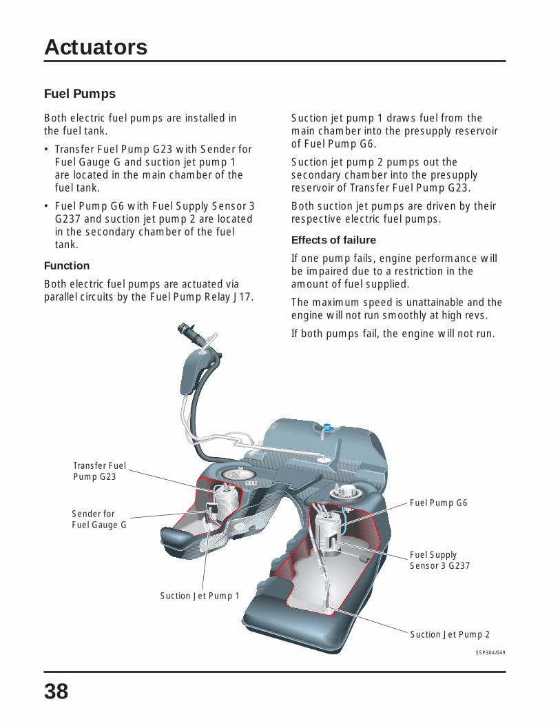
Fuel Pumps
Both electric fuel pumps are installed inthe fuel tank.
• Transfer Fuel Pump G23 with Sender forFuel Gauge G and suction jet pump 1are located in the main chamber of thefuel tank.
• Fuel Pump G6 with Fuel Supply Sensor 3G237 and suction jet pump 2 are locatedin the secondary chamber of the fueltank.
Function
Both electric fuel pumps are actuated viaparallel circuits by the Fuel Pump Relay J17.
Suction jet pump 1 draws fuel from themain chamber into the presupply reservoirof Fuel Pump G6.
Suction jet pump 2 pumps out thesecondary chamber into the presupplyreservoir of Transfer Fuel Pump G23.
Both suction jet pumps are driven by theirrespective electric fuel pumps.
Effects of failure
If one pump fails, engine performance willbe impaired due to a restriction in theamount of fuel supplied.
The maximum speed is unattainable and theengine will not run smoothly at high revs.
If both pumps fail, the engine will not run.
SSP304/049
Transfer FuelPump G23
Sender forFuel Gauge G
Suction Jet Pump 1
Suction Jet Pump 2
Fuel SupplySensor 3 G237
Fuel Pump G6
39
Actuators
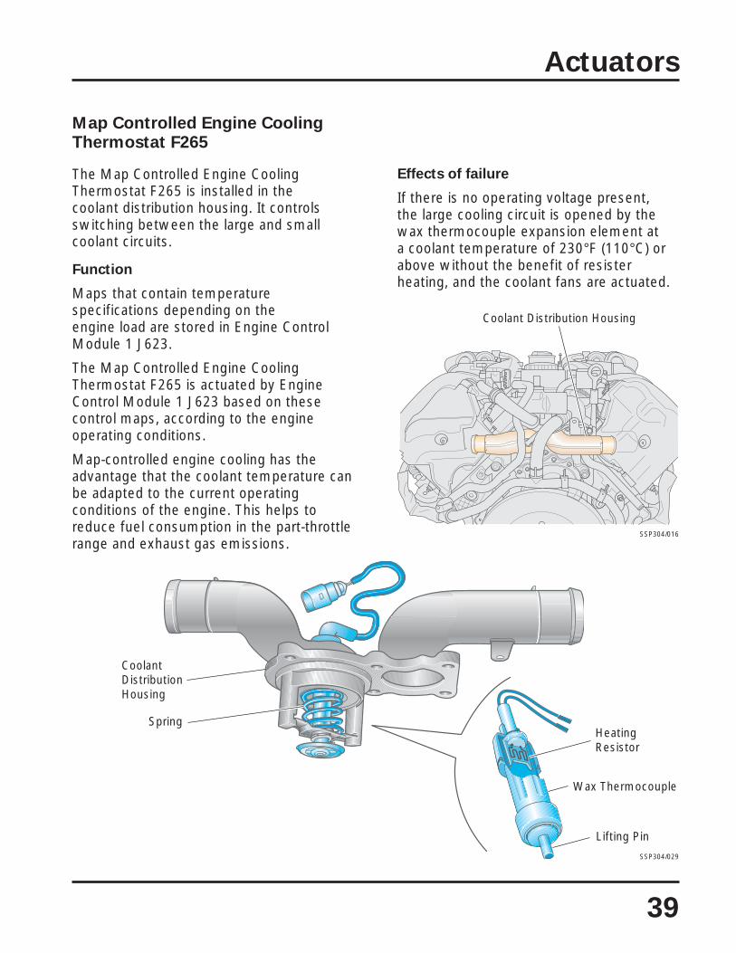
Map Controlled Engine CoolingThermostat F265
The Map Controlled Engine CoolingThermostat F265 is installed in thecoolant distribution housing. It controlsswitching between the large and smallcoolant circuits.
Function
Maps that contain temperaturespecifications depending on theengine load are stored in Engine ControlModule 1 J623.
The Map Controlled Engine CoolingThermostat F265 is actuated by EngineControl Module 1 J623 based on thesecontrol maps, according to the engineoperating conditions.
Map-controlled engine cooling has theadvantage that the coolant temperature canbe adapted to the current operatingconditions of the engine. This helps toreduce fuel consumption in the part-throttlerange and exhaust gas emissions.
Coolant Distribution Housing
SSP304/016
Effects of failure
If there is no operating voltage present,the large cooling circuit is opened by thewax thermocouple expansion element ata coolant temperature of 230°F (110°C) orabove without the benefit of resisterheating, and the coolant fans are actuated.
SSP304/029
CoolantDistributionHousing
Lifting Pin
Wax Thermocouple
HeatingResistor
Spring

M
40
Actuators
Continued Coolant Circulation
The After-Run Coolant Pump V51 is locatedon cylinder bank I of the V10 TDI engine onthe vibration damper side.
The After-Run Coolant Pump V51 isactuated by Auxiliary Engine Coolant PumpRelay J496.
The Auxiliary Engine Coolant Pump RelayJ496 is installed in the electronics box inthe plenum chamber.
Function
When the engine is switched off, theAfter-Run Coolant Pump V51 will remainactivated for a maximum of 10 minutes.In this way, controlled cooling of the engineis achieved.
Effects of failure
If either the Auxiliary Engine Coolant PumpRelay J496 or the After-Run Coolant PumpV51 fails, continued coolant circulation willno longer be possible.
If the Auxiliary Engine Coolant Pump RelayJ496 is defective, a fault will be stored.
A defective After-Run Coolant Pump V51cannot be detected.
Electrical circuit
J623 Engine Control Module 1
J496 Auxiliary Engine Coolant Pump Relay
V51 After-Run Coolant Pump
After-RunCoolantPump V51
SSP304/027
VibrationDamper
J623
V51
J496
SSP304/067

41
Actuators
Fuel Cooling
The Pump for Fuel Cooler V166 islocated on cylinder bank I on thevibration damper side of the engine.
The Pump for Fuel Cooler V166 is actuatedby Relay for Pump, Fuel Cooling J445.
The Relay for Pump, Fuel Cooling J445 isinstalled in the electronics box in theplenum chamber.
Function
The Engine Control Module 1 J623actuates the Relay for Pump, Fuel CoolingJ445 at and above a fuel temperature ofapproximately 158°F (70°C).
The Engine Control Module 1 J623 sends aworking current to the Pump for FuelCooler V166 and the fuel cooler is thensurrounded by engine coolant.
Fuel temperature will drop.
Effects of failure
If the Relay for Pump, Fuel Cooling J445 orPump for Fuel Cooler V166 fails, fuel will nolonger be cooled.
The fuel tank and the Sender for FuelGauge G could become damaged.
A defective Relay for Pump, Fuel CoolingJ445 is stored as a fault.
A defective Pump for Fuel Cooler V166cannot be detected.
Electrical circuit
J623 Engine Control Module 1
J445 Relay for Pump, Fuel Cooling
V166 Pump for Fuel Cooler
Pump forFuel CoolerV166
SSP304/009
VibrationDamper
M
SSP304/068
V166
J445
J623

42
Functional Diagram
EDC 16 Functional Diagramfor V10 TDI Engine
Components
F Brake Light SwitchF8 Kick Down SwitchF47 Brake Pedal SwitchF60 Closed Throttle Position SwitchF265 Map Controlled Engine Cooling Thermostat
G6 Fuel Pump (Presupply Pump)G23 Transfer Fuel PumpG28 Engine Speed SensorG31 Charge Air Pressure SensorG39 Heated Oxygen SensorG40 Camshaft Position SensorG42 Intake Air Temperature SensorG62 Engine Coolant Temperature SensorG70 Mass Air Flow SensorG79 Throttle Position SensorG81 Fuel Temperature SensorG83 Engine Coolant Temperature Sensor
(on Radiator)G133 Flexible Fuel Sensor
J17 Fuel Pump RelayJ52 Glow Plug RelayJ317 Power Supply (Terminal 30, B+) RelayJ445 Relay for Pump, Fuel CoolingJ496 Auxiliary Engine Coolant Pump RelayJ623 Engine Control Module 1
N18 EGR Vacuum Regulator Solenoid ValveN240 Valve for Pump/Injector, Cylinder 1N241 Valve for Pump/Injector, Cylinder 2N242 Valve for Pump/Injector, Cylinder 3N243 Valve for Pump/Injector, Cylinder 4N244 Valve for Pump/Injector, Cylinder 5
Q10 Glow Plug 1Q11 Glow Plug 2Q12 Glow Plug 3Q13 Glow Plug 4Q14 Glow Plug 5
V51 After-Run Coolant PumpV157 Motor for Intake FlapV166 Pump for Fuel CoolerV280 Turbocharger 1 ServomotorV281 Turbocharger 2 Servomotor
Z19 Oxygen Sensor Heater
Additional Signals
1 Drivetrain CAN Data Bus (High)
2 Drivetrain CAN Data Bus (Low)
3 Radiator Fan Output Stage 1
4 Radiator Fan Output Stage 2
5 16-Pin Connector (Diagnosis Connection) T16
6 Cruise Control Switch E45 (On/Off)
7 Road Speed Signal
8 Generator Terminal DFM
9 Starter Relay J53
A
B
C
D
E
F
G
H
Color Coding
Input Signal
Output Signal
Positive
Ground
CAN Data Bus
Bidirectional
Connections WithinFunctional Diagram

43
M M M
J623
30
15
6 7 8 9N240 N241 N242 N243 N244 G81
43
J317
λ
G39 Z19
B
M
V157
M
V280 V281
N18
C
F265
M
M
J496
V51
J445
V166
G62 G83 G133
+
G40G31 G42
F
G28 F60/F8 G79
J17
G23
H
G
G70
FF47
C
A
J52
5
E
Q10...Q14
1
2
D
G6
Functional Diagram
SSP304/001a

44
Functional Diagram
Components
G108 Heated Oxygen Sensor 2G246 Mass Air Flow Sensor 2G248 Fuel Temperature Sensor 2G299 Intake Air Temperature Sensor 2G447 Charge Air Pressure Sensor 2
J495 Glow Plug Relay 2J624 Engine Control Module 2J689 Power Supply Relay (Terminal 30, B+)
Relay 2
N213 Valve 2 for EGRN245 Valve for Pump/Injector, Cylinder 6N303 Valve for Pump/Injector, Cylinder 7N304 Valve for Pump/Injector, Cylinder 8N305 Valve for Pump/Injector, Cylinder 9N306 Valve for Pump/Injector, Cylinder 10
Q15 Glow Plug 6Q16 Glow Plug 7Q17 Glow Plug 8Q18 Glow Plug 9Q19 Glow Plug 10
V275 Intake Flap Motor 2
Z28 Oxygen Sensor Heater 2
Additional Signals
1 Drivetrain CAN Data Bus (High)
2 Drivetrain CAN Data Bus (Low)
5 16-Pin Connector (Diagnosis Connection)T16
A
B
C
D
E
F
G
H
Color Coding
Input Signal
Output Signal
Positive
Ground
CAN Data Bus
Bidirectional
Connections WithinFunctional Diagram

45
Functional Diagram
SSP304/001b
N213
C
J624
N245 N303 N304 N305 N306 G248 G447 G299
1 2
J689
λ
G108 Z28
MH
V275
E F
A
B
30
15
J495
D
5
Q15...Q19
G246
G

46
Notes

47
Notes

48
Notes

49
Knowledge Assessment
An on-line Knowledge Assessment (exam) is available for this Self-Study Program.
The Knowledge Assessment may or may not be required for Certification.
You can find this Knowledge Assessment at:
www.vwwebsource.com
From the vwwebsource.com Homepage, do the following:
– Click on the Certification tab
– Type the course number in the Search box
– Click “Go!” and wait until the screen refreshes
– Click “Start” to begin the Assessment
For Assistance, please call:
Certification Program Headquarters
1 – 877 – CU4 – CERT(1 – 877 – 284 – 2378)
(8:00 a.m. to 8:00 p.m. EST)
Or, E-Mail:


Touareg Electronic Diesel Control EDC 16Design and Function
Volkswagen of America, Inc.3800 Hamlin RoadAuburn Hills, MI 48326Printed in U.S.A.March 2004
Self-Study ProgramCourse Number 89P303


