+ All Categories
Home > Documents > 8th Workshop on Electronics for LHC Experiment, Colmar, France, 10 Sep. 2002 R.Ichimiya, ATLAS Japan...

8th Workshop on Electronics for LHC Experiment, Colmar, France, 10 Sep. 2002 R.Ichimiya, ATLAS Japan...

Date post: 19-Dec-2015
Category:
View: 214 times
Download: 0 times
Share this document with a friend
Popular Tags:
20
8th Workshop on Electronics for LHC Experiment, Colmar, France, 10 Sep. 2002 R.Ichimiya, ATLAS Japan 1 Sector Logic Sector Logic Implementation for the Implementation for the ATLAS Endcap Level-1 ATLAS Endcap Level-1 Muon Trigger Muon Trigger Contents ATLAS Level-1 Trigger system Endcap Muon Trigger system Sector Logic Design Prototype Test Results Summary R. Ichimiya (Kobe university)
Transcript

8th Workshop on Electronics for LHC Experiment, Colmar, France, 10 Sep. 2002 R.Ichimiya, ATLAS Japan 1

Sector Logic Implementation Sector Logic Implementation for the ATLAS Endcap Level-1 for the ATLAS Endcap Level-1

Muon TriggerMuon Trigger

Contents

• ATLAS Level-1 Trigger system

• Endcap Muon Trigger system

• Sector Logic Design

• Prototype

• Test Results

• Summary

R. Ichimiya(Kobe university)

8th Workshop on Electronics for LHC Experiment, Colmar, France, 10 Sep. 2002 R.Ichimiya, ATLAS Japan 2

ATLAS Trigger and DAQ systemATLAS Trigger and DAQ systemATLAS Trigger & DAQ System Level-1 Trigger System

8th Workshop on Electronics for LHC Experiment, Colmar, France, 10 Sep. 2002 R.Ichimiya, ATLAS Japan 3

TGC M2

TGC M3

TGC M1

Toroidal Field

TGC EI/FI

Muon Trigger system

Muon Trigger system

Muon Trigger:based on momentum measurement in

the magnetic field.

Trigger Chambers:• For endcap region (|| >1.05):

Thin Gap Chamber(TGC)

• For barrel region (|| <1.05):

Resistive Plate Chamber(RPC)

|| =1.05

Muon Trigger Chambers

R

Z

B

InteractionPoint (IP)

8th Workshop on Electronics for LHC Experiment, Colmar, France, 10 Sep. 2002 R.Ichimiya, ATLAS Japan 4

Endcap Muon TriggerEndcap Muon TriggerEndcap Muon Triggerfinds muon’s tracks using 7

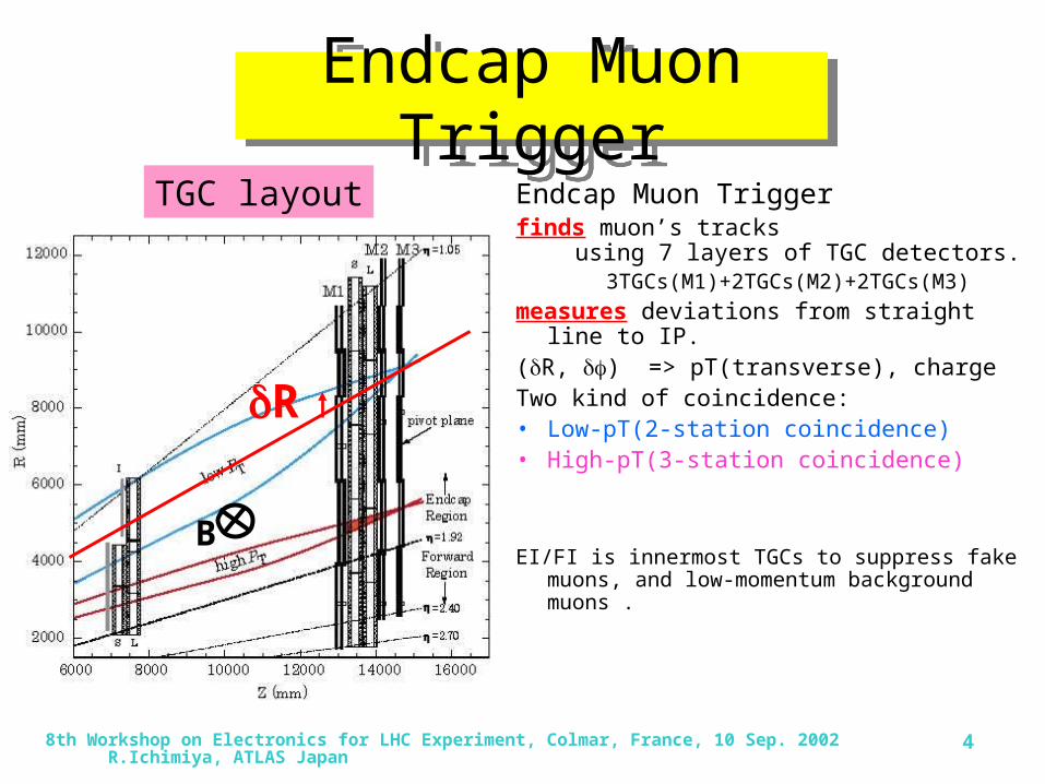
layers of TGC detectors. 3TGCs(M1)+2TGCs(M2)+2TGCs(M3)

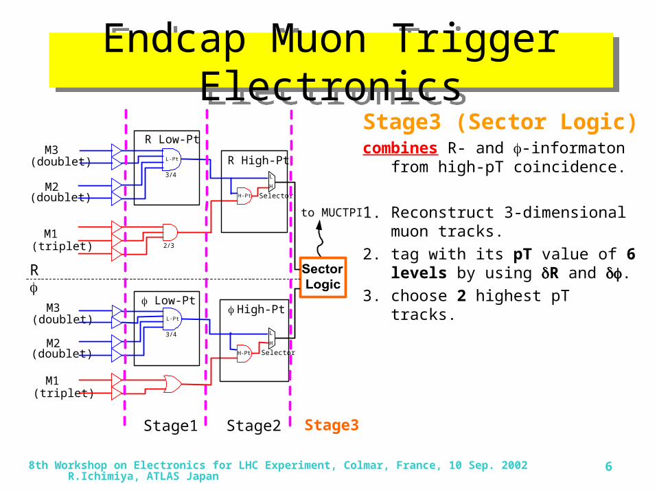
measures deviations from straight line to IP. (R, ) => pT(transverse), chargeTwo kind of coincidence:• Low-pT(2-station coincidence)• High-pT(3-station coincidence)

EI/FI is innermost TGCs to suppress fake muons, and low-momentum background muons .

R

TGC layout

B

8th Workshop on Electronics for LHC Experiment, Colmar, France, 10 Sep. 2002 R.Ichimiya, ATLAS Japan 5

Endcap Muon Trigger ElectronicsEndcap Muon Trigger ElectronicsStage1 (low-pT block)• 2-station coincidence between

the hits in the Doublets.

Stage2 (high-pT block)• 3-station coincidence between

Low-pT and the hits in the Triplet.

Measure R, in parallel.

M3(doublet)

R Low-Pt

Sector Logic

R High-Pt

High-Pt

Selector

SelectorH-Pt

H-Pt

L

H

H

L

to MUCTPI

M2(doublet)

M1(triplet)

M3(doublet)

M2(doublet)

M1(triplet)

L-Pt

3/4

2/3

Low-Pt

R

L-Pt

3/4

Stage1 Stage2 Stage3

8th Workshop on Electronics for LHC Experiment, Colmar, France, 10 Sep. 2002 R.Ichimiya, ATLAS Japan 6

Endcap Muon Trigger ElectronicsEndcap Muon Trigger Electronics

Stage3 (Sector Logic)combines R- and -informaton from

high-pT coincidence.

1. Reconstruct 3-dimensional muon tracks.

2. tag with its pT value of 6 levels by using R and .

3. choose 2 highest pT tracks.

M3(doublet)

R Low-Pt

R High-Pt

High-Pt

Selector

SelectorH-Pt

H-Pt

L

H

H

L

to MUCTPI

M2(doublet)

M1(triplet)

M3(doublet)

M2(doublet)

M1(triplet)

L-Pt

3/4

2/3

Low-Pt

R

L-Pt

3/4

Stage1 Stage2 Stage3

8th Workshop on Electronics for LHC Experiment, Colmar, France, 10 Sep. 2002 R.Ichimiya, ATLAS Japan 7

Trigger SectorTrigger SectorAn Trigger Sectorisa segment of the trigger electronics.

– 96 Endcap Trigger Sectors (|| <2.06)

– 48 Forward Trigger Sectors (|| >2.06)consists of

– 148 Sub-Sectors (Endcap Trigger Sector)– 64 Sub-Sectors (Forward Trigger

Sector)

An Sub-Sectorisa unit for position of tracks (RoI).

8th Workshop on Electronics for LHC Experiment, Colmar, France, 10 Sep. 2002 R.Ichimiya, ATLAS Japan 8

ATLAS Troidal MagnetsATLAS Troidal Magnets

Non-uniformity of magnetic field

Map of Magnetic FieldsHitmap on the TGC for the same pT muons

R and vary point by point.

To keep momentum resolution high,

We divide TGC plane into sub-sectors, where pT measurement is performed independently.

8th Workshop on Electronics for LHC Experiment, Colmar, France, 10 Sep. 2002 R.Ichimiya, ATLAS Japan 9

Track Finding & pT measurementTrack Finding & pT measurement• Input: (R, R)+(, )

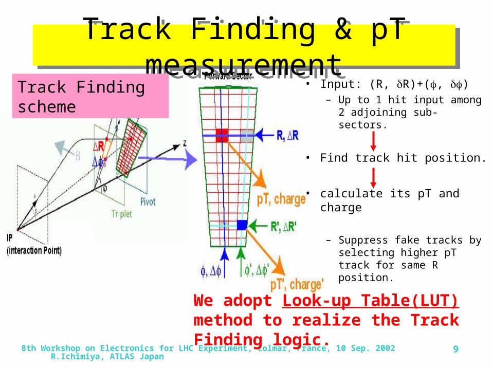
– Up to 1 hit input among 2 adjoining sub-sectors.

• Find track hit position.

• calculate its pT and charge

– Suppress fake tracks by selecting higher pT track for same R position.

Track Finding scheme

We adopt Look-up Table(LUT) method to realize the Track Finding logic.

8th Workshop on Electronics for LHC Experiment, Colmar, France, 10 Sep. 2002 R.Ichimiya, ATLAS Japan 10

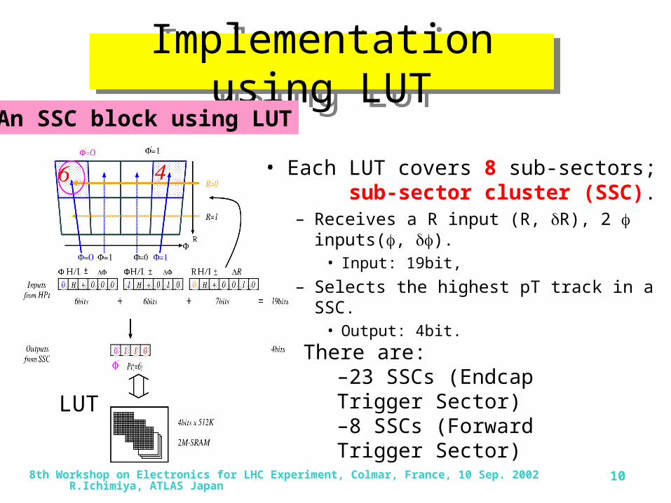
Implementation using LUTImplementation using LUT

• Each LUT covers 8 sub-sectors; sub-sector cluster (SSC).

– Receives a R input (R, R), 2 inputs(, ).• Input: 19bit,

– Selects the highest pT track in a SSC.• Output: 4bit.

LUT

An SSC block using LUT

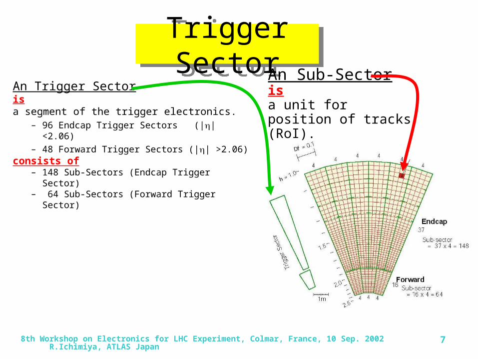
There are:–23 SSCs (Endcap Trigger Sector)–8 SSCs (Forward Trigger Sector)

8th Workshop on Electronics for LHC Experiment, Colmar, France, 10 Sep. 2002 R.Ichimiya, ATLAS Japan 11

Track Selection LogicTrack Selection Logic

• Track Selection Logic selects 2 highest-pT tracks from the SSC outputs.

Track Selection Logic scheme

Divide into 2 stages:•6 Pre-Selectors:

Collects same pT tracks and choose 2 lowest tracks.

•Final-Selector:Picks up 2 highest pT tracks among 12 candidates of 6 pre-selectors.

8th Workshop on Electronics for LHC Experiment, Colmar, France, 10 Sep. 2002 R.Ichimiya, ATLAS Japan 12

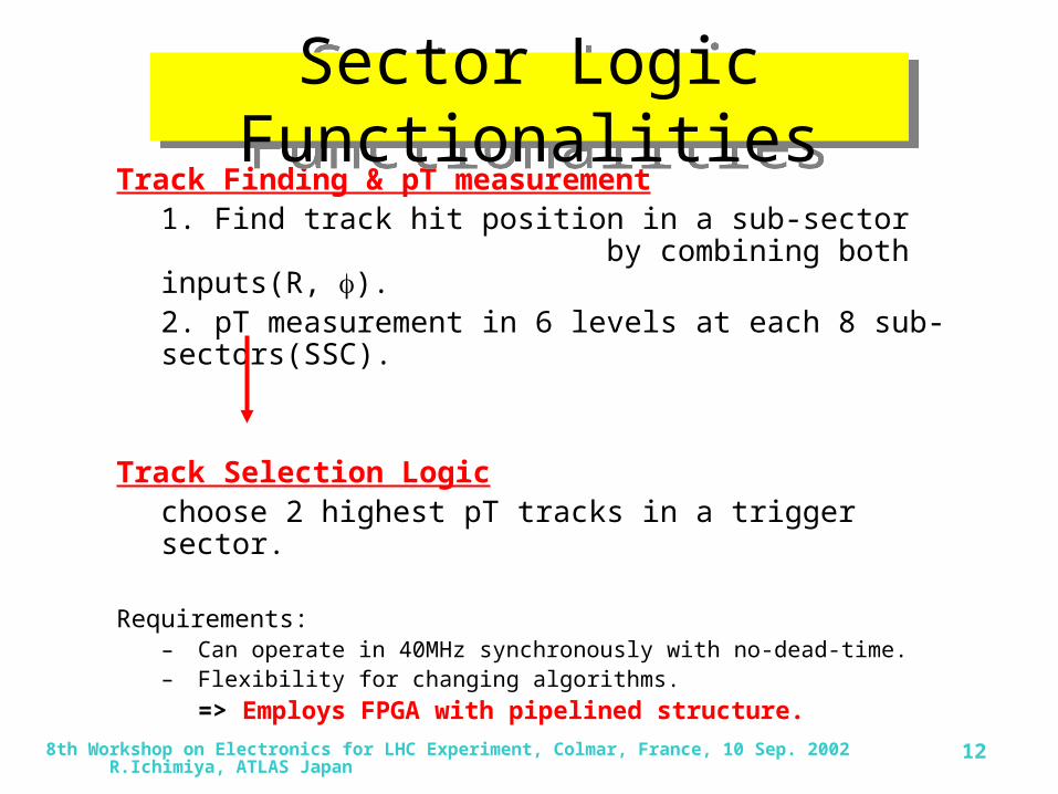
Track Finding & pT measurement1. Find track hit position in a sub-sector by combining both inputs(R, ).2. pT measurement in 6 levels at each 8 sub-sectors(SSC).

Track Selection Logicchoose 2 highest pT tracks in a trigger sector.

Requirements:– Can operate in 40MHz synchronously with no-dead-time.– Flexibility for changing algorithms.

=> Employs FPGA with pipelined structure.

Sector Logic FunctionalitiesSector Logic Functionalities

8th Workshop on Electronics for LHC Experiment, Colmar, France, 10 Sep. 2002 R.Ichimiya, ATLAS Japan 13

Prototype-0: FPGA(Virtex-EM)Prototype-0: FPGA(Virtex-EM)

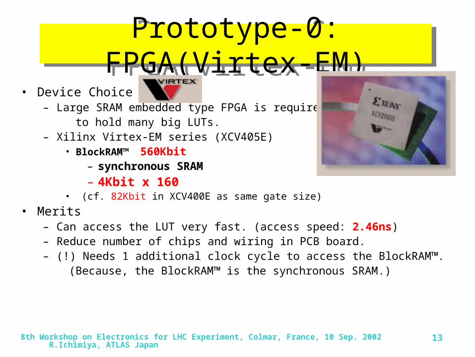
• Device Choice– Large SRAM embedded type FPGA is required to hold many big LUTs.– Xilinx Virtex-EM series (XCV405E)

• BlockRAM™ 560Kbit– synchronous SRAM

– 4Kbit x 160• (cf. 82Kbit in XCV400E as same gate size)

• Merits – Can access the LUT very fast. (access speed: 2.46ns)– Reduce number of chips and wiring in PCB board.– (!) Needs 1 additional clock cycle to access the BlockRAM™. (Because, the BlockRAM™ is the synchronous SRAM.)

8th Workshop on Electronics for LHC Experiment, Colmar, France, 10 Sep. 2002 R.Ichimiya, ATLAS Japan 14

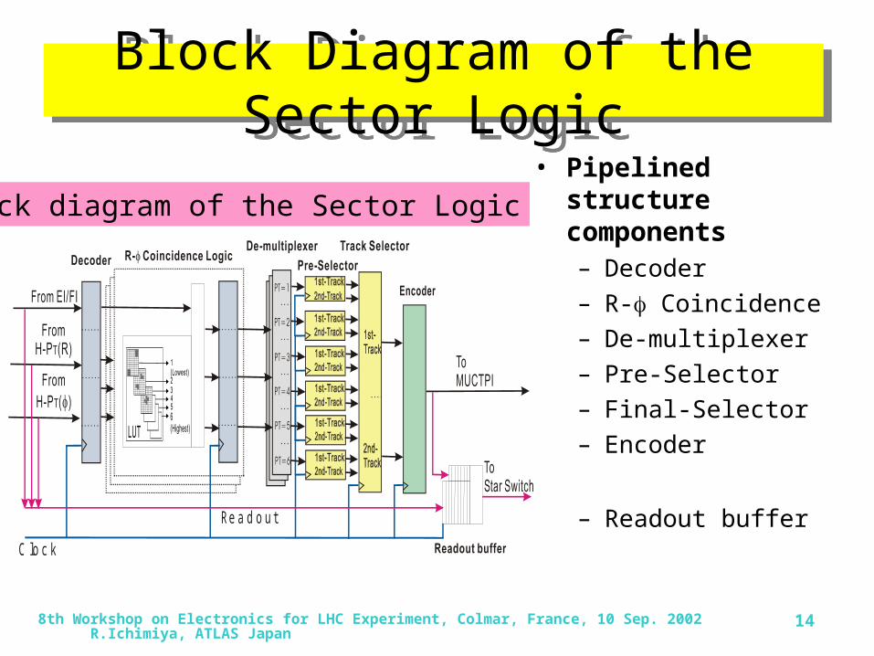
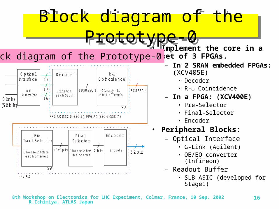
Block Diagram of the Sector LogicBlock Diagram of the Sector Logic• Pipelined structure

components– Decoder

– R- Coincidence

– De-multiplexer

– Pre-Selector

– Final-Selector

– Encoder

– Readout buffer

C lo c k

Re a d o u t

Block diagram of the Sector Logic

8th Workshop on Electronics for LHC Experiment, Colmar, France, 10 Sep. 2002 R.Ichimiya, ATLAS Japan 15

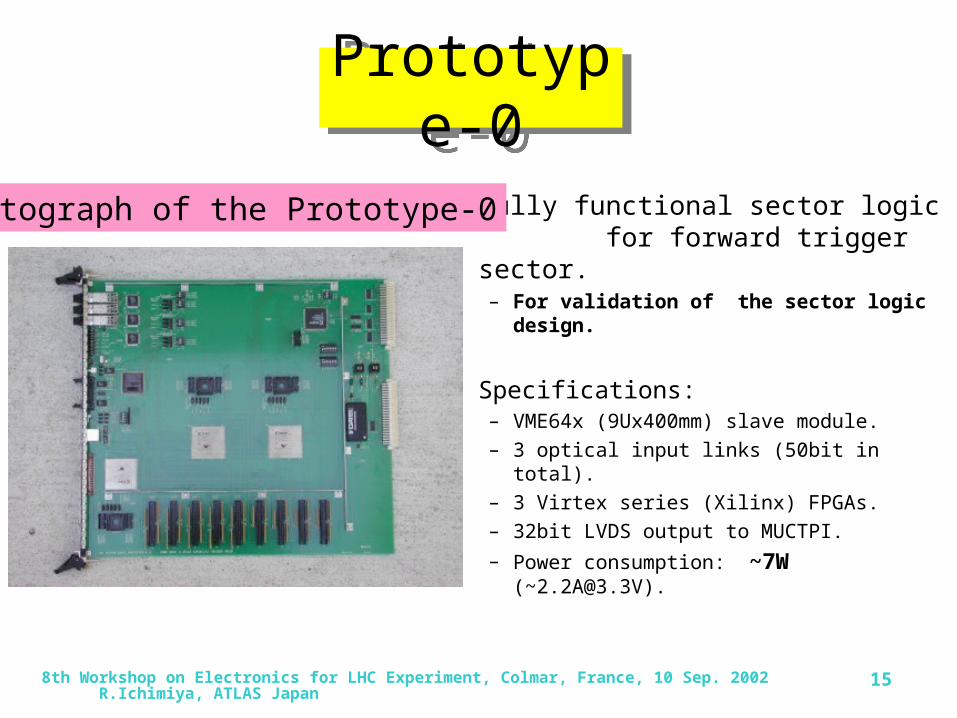
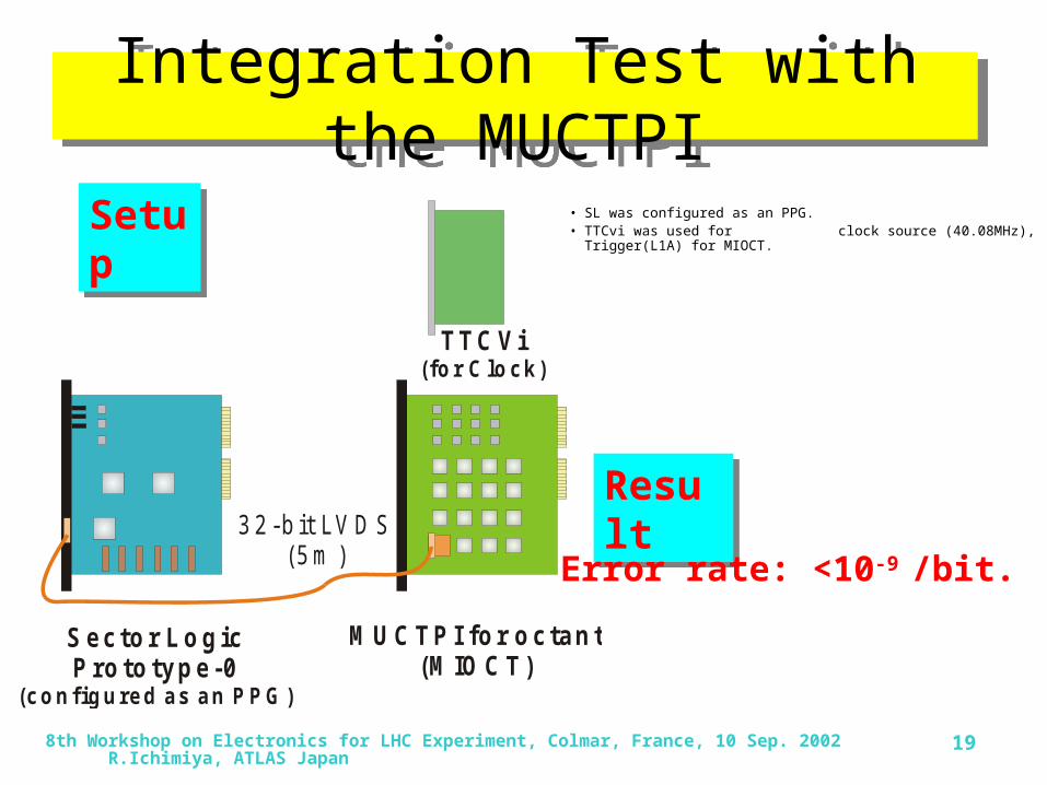
Prototype-0Prototype-0

Fully functional sector logic for forward trigger sector.– For validation of the sector logic design.

Specifications:– VME64x (9Ux400mm) slave module.

– 3 optical input links (50bit in total).

– 3 Virtex series (Xilinx) FPGAs.

– 32bit LVDS output to MUCTPI.

– Power consumption: ~7W ([email protected]).

Photograph of the Prototype-0

8th Workshop on Electronics for LHC Experiment, Colmar, France, 10 Sep. 2002 R.Ichimiya, ATLAS Japan 16

Block diagram of the Prototype-0

Block diagram of the Prototype-0

• Implement the core in a set of 3 FPGAs.– In 2 SRAM embedded FPGAs:

(XCV405E)• Decoder• R- Coincidence

– In a FPGA: (XCV400E)• Pre-Selector• Final-Selector• Encoder

• Peripheral Blocks:– Optical Interface

• G-Link (Agilent) • OE/EO converter (Infineon)

– Readout Buffer• SLB ASIC (developed for Stage1)

O p tic a lIn te rfa c e

3 lin ks(5 0 b it)

O ED e se ria lize

D e c o d e r

D isp a tc he a c h SSC s

R-C o in c id e n c e

C la ssify h its in to 6 p T le ve ls

1 9 x8 SSC s

X8

PreTra c k Se le c to r

C h o o se 2 h its ine a c h p T le ve l

Fin a l Se le c to r

C h o o se 2 h its in a Se c to r

1 6 x6 p Ts

En c o d e r

En c o d e2 h its

FPG A 0 (SSC 0 -SSC 5 ), FPG A 1 (SSC 6 -SSC 7 )

FPG A 2

8 X8 SSC s

3 2 b it

X6

1 7

1 7

1 6

Block diagram of the Prototype-0

8th Workshop on Electronics for LHC Experiment, Colmar, France, 10 Sep. 2002 R.Ichimiya, ATLAS Japan 17

Performance Test (timing margin)

Performance Test (timing margin)

• Input Data:– Data were fed through

Optical Link (20m) with G-Link Serializer.

• Output Data:– Read out by FIFO module,

instead of MUCTPI.

(*) Input and Output are synchronized to 40.08MHz.

P P G G -L in k T x

F IF O m o d u le

G -L in k(2 0 m )

S e c to r L o g icP ro to ty p e -0

SetupSetup data path

Can operate up to 51.5MHz.

ResultResult

timing margin > 5.5ns (@40MHz)

8th Workshop on Electronics for LHC Experiment, Colmar, France, 10 Sep. 2002 R.Ichimiya, ATLAS Japan 18

Performance Test (functional check)Performance Test (functional check)

• Outputs are compared with the test vectors which generated by the simulator.

• 1.3M events were tested. No error were found.

ResultResult

Simulate these blocks for generating Test Vectors fed to the Sector Logic.

Generate muon tracks (up to 6 tracks).

SetupSetup

8th Workshop on Electronics for LHC Experiment, Colmar, France, 10 Sep. 2002 R.Ichimiya, ATLAS Japan 19

Integration Test with the MUCTPIIntegration Test with the MUCTPI

• SL was configured as an PPG.• TTCvi was used for clock source (40.08MHz), Trigger(L1A)

for MIOCT.

S e c to r L o g icP ro to ty p e -0

(c o n f ig u re d a s a n P P G )

M U C T P I fo r o c ta n t(M IO C T )

3 2 -b i t LV D S(5 m )

T T C V i( fo r C lo c k )

SetupSetup

ResultResult

Error rate: <10-9 /bit.

8th Workshop on Electronics for LHC Experiment, Colmar, France, 10 Sep. 2002 R.Ichimiya, ATLAS Japan 20

SummarySummary• Designed the Sector Logic for endcap muon trigger.

– The core is R- coincidence and Track Selection Logic.

– SRAM embedded FPGA for the LUT of R- coincidence.

– Pipelined structure.

• Fabricated and Tested fully functional Sector Logic Prototype.– FPGA based design.

– It worked up to 51.5MHz; 5.5ns margin @40MHz.

– No error with 1.3M input patterns.

– Verified the data transmission from the Sector Logic to the MUCTPI.

The design and the prototype implementation satisfies requirements for the endcap muon Sector Logic.


Recommended