11
Data Center Water cooled chiller plant (cp/vs) Design Envelope application guide File No: 9.573 Date: december 16, 2014 Supersedes: 9.573 Date: november 14, 2014

7/21/2019 9 573 WaterCooledChillerPlantCPVS
http://slidepdf.com/reader/full/9-573-watercooledchillerplantcpvs 1/10
Data Center
Water cooled
chiller plant(cp/vs)
Design Envelope
application guide
File No: 9.573
Date: december 16, 2014
Supersedes: 9.573
Date: november 14, 2014
7/21/2019 9 573 WaterCooledChillerPlantCPVS
http://slidepdf.com/reader/full/9-573-watercooledchillerplantcpvs 2/10
design envelopeapplication guides
p
erformance improvements are among the top priorities of many building
professionals today. Whether you are a developer, design consultant, engineer,
contractor, facility manager or owner, chances are that you face increasingdemands to not only reduce costs, but also deliver performance improvements. Public
awareness on multiple levels – from the individual all the way through to government
bodies – has grown to the point that energy conservation, carbon reduction, tenant
comfort, and other health and environment-driven practices are key objectives for any
prominent, sizeable building project.
To support and sustain this paradigm shift, Armstrong has developed a suite of ad-
vanced fluid flow and HVAC offerings that we call ‘Design Envelope solutions’. Design
Envelope solutions integrating intelligent demand-based control to deliver optimal
performance and the lowest possible cost, both at commissioning and throughout their
full operating life.
This document is one of our Design Envelope Application Guides, a set of booklets that
discuss a broad range of real-world HVAC scenarios. In each scenario the use of DesignEnvelope technology can result in tremendous improvements in performance of your
HVAC installation (compared to standard industry practice) and ultimately your building
- technically, financially, and environmentally.
The intent of this Application Guide is to present HVAC System designers with an
alternative to standard practices for design layout, configuration, and design calculations
and help you leverage the full potential of Armstrong Design Envelope solutions. Each
Application Guide addresses a specific system configuration for HVAC or data center
applications. The system configurations cover heating and cooling scenarios, including
circuit configurations ranging from all constant flow, to full variable flow and variable
speed plant configurations. The Application Guides will present piping arrangements,
valving requirements, de-coupler configurations, instrumentation locations, control
system options, and the associated impact on first cost and life-cycle costs. The fullseries of application guides is available for download from Armstrong’s website at www.
armstrongfluidtechnology.com

7/21/2019 9 573 WaterCooledChillerPlantCPVS
http://slidepdf.com/reader/full/9-573-watercooledchillerplantcpvs 3/10
application directory
This guide covers:
hvac
cooling
9.561 – Water cooled chiller plant (all-variable)
9.562 – Water cooled chiller plant (cp/vs)
9.563 – Water cooled chiller plant with economizer
9.564 – Ground source heat pump system (vp)
heating
9.565 – Condensing boiler plant (vp)
9.566 – Condensing boiler plant (cp/vs)
9.567 – Closed circuit heat pump system (vp)
district cooling
9.568 – Water cooled central plant (all-variable) 9.569 – Water cooled central plant (cp/vs)
9.570 – Water cooled central plant (vp/vs)
data centres
cooling
9.571 – Water cooled chiller plant with economizer (vp)
9.572 – Water cooled chiller plant (all-variable)
9.573 – Water cooled chiller plant (cp/vs)
VP = Variable primary flow
CP/VS = Constant primary flow / variable secondary flow
VP/VS = Variable primary flow / variable secondary flow
All-variable = All variable chiller plant, variable primary flow, variable secondary flow, variable condenser flow

7/21/2019 9 573 WaterCooledChillerPlantCPVS
http://slidepdf.com/reader/full/9-573-watercooledchillerplantcpvs 4/10
design envelope
application guide
Data Center
Water cooled chiller plant (cp/vs)
4
This application guide considers a typical chilled water sys-
tem in a Tier III data center installation. This type of system is
a cost effective way of providing cooled water through crac (Computer Room Air Conditioning) units that are used to cool
the servers within the data center. The need for constant and
reliable service delivery from data centers demands a high level
of infrastructure availability as defined by the Uptime Institute.
Tier III classification requires N+1 redundancy where, in the case
of the chilled water system, the plant has duplicated distribution
pipework and standby equipment in case of failure. A character-
istic of Tier III data centers is that plant items are not required
to be concurrently maintainable and as such there will be a
shutdown period to enable major equipment maintenance.
application details
Equipment Water-cooled chillers 1-5
Economizers •
Use Data center •
Configuration Const. primary flow •
Var. secondary flow •
Const. condenser flow •
fig. 2
conventional plant layout.
with base mounted end suction pumps and wall
mounted VFD’s controlled by bms on secondary loop
fig. 1
design envelope plant layout.
design envelope benefits summary
Design Envelope benefit Design Envelope savingsover conventional plant
Lowest installed cost 32%
Lowest operating cost 14%
Lowest environmental
cost/impact
Annual reduction in greenhouse
gas emissions (tonnes): 690
Total Design Envelope
1st year savings 15%

7/21/2019 9 573 WaterCooledChillerPlantCPVS
http://slidepdf.com/reader/full/9-573-watercooledchillerplantcpvs 5/10
design envelope
application guide
Data Center
Water cooled chiller plant (cp/vs)
5
plant layoutdesign envelope vs. conventional
Design Envelope solution
fig. 1 describes a plant layout based on Armstrong DesignEnvelope Technology.
Primary pumps are Design Envelope 4300 vertical In-line featur-
ing integrated controls with optimized pairing and selection
for peak efficiency at part load. They are supplied with Suction
Guides and Flo-Trex triple duty valves for reduced installed cost.
They are sequenced with the chillers and their speeds recom-
mended by OptiVisor™ to balance the primary and secondary
flows while providing the flow required to maintain the storage
tank temperature, thus maximizing the delta T and maintaining
the minimum flow required by the running chillers. The primary
flow can be read from the Design Envelope pumps or from
existing flow sensors.
The optimum number of chillers to run is selected by OptiVisor
based on heat load. To improve efficiency, the load is distributed
among the chillers to maximize the exchange surfaces. When
the cooling towers and condenser pumps are dedicated, as in
this case, using more chillers than strictly needed allows lower
condenser temperatures, even using less fan energy. Combined
with variable condenser flow, this substantially reduces the
condenser pumping energy. The chilled water supply setpoint
is adjusted (if allowed by the loads) also based on heat load,
further reducing the required chiller energy use.
Secondary pumps are again Design Envelope 4300 vertical
inline fitted with Suction Guides and Flo-Trex valves. The bms
adjusts the speed of the pumps to satisfy the demand measured
by zone differential pressure sensors or zones return tempera-
tures. In all speed control modes the optimal number of pumps
to run is recommended by OptiVisor using Parallel Sensorless™
control. Each of these pumps alone can supply enough flow
to satisfy over 90% of the design heat load, which is in most
data centers all that’s seen in the first years of operation. The
secondary flow can be read from the Design Envelope pumps or
the existing flow sensors.
Design Envelope plant Conventional plant
Primary loop Design Envelope 4300 with Suction Guides
and Flo-Trex Valves
3 Constant speed chillers with one base mounted end suction
pump per chiller
Secondary loop Design Envelope 4300 with Suction Guides
and Flo-Trex Valves
3 Variable speed base mounted end suction pumps
Condenser loop Design Envelope 4300 with Suction Guides
and Flo-Trex Valves
3 Constant speed base mounted end suction pumps
Design Envelope 4300 pumps are sequenced with the chillers
and their speed is recommended by OptiVisor based on heatload. Adjusting the condenser flow not only reduces the pump-
ing energy use, but also increases the cooling tower efficiency
resulting in lower condenser water temperatures and/or less
fans energy use. Tower fans are sequenced with the chillers and
their speed recommended by OptiVisor to balance the fans and
chillers energy use, further increasing efficiency.
Conventional solution
A traditional design approach is shown in fig. 2 where a me-
chanical layout comprised of primary, secondary and condenser
loops is presented. Additionally, typical bms (Building Manage-ment System) connections are also illustrated.
The cooling plant is based on constant speed compressor type,
water cooled chillers. Cooled water on the evaporator side is
circulated by constant speed, base mounted end suction, circu-
lating pumps to a low loss header. Each chiller has a dedicated
primary pump.
An economizer system is provided, using a plate and frame heat
exchanger (one per chiller) with control valves to enable, during
cooler periods (generally about 40f, depending on wet bulb),
free cooling from the cooling tower to cool the chilled water
with the chiller taken out of the circuit and disabled, saving
power and reducing running costs.
Secondary cooling base mounted end suction circulating
pumps, taking their source from the same header, circulate the
water into the data center to cool the servers, through CRACs.
The secondary pumps can run at variable speed and their speed
is controlled by looking at the difference between the pres-
sure measured by a differential pressure transducer, located
at or near to the crac and the pressure setting of the set point
controller. The Set Point Controller will be programmed with pid
software to send an analogue signal to the pump drives to de-
termine the speed. There will be a standby pressure transducer.
7/21/2019 9 573 WaterCooledChillerPlantCPVS
http://slidepdf.com/reader/full/9-573-watercooledchillerplantcpvs 6/10
design envelope
application guide
Data Center
Water cooled chiller plant (cp/vs)
6
design envelope benefits summary
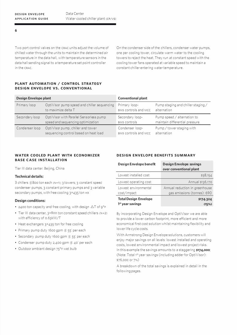
By incorporating Design Envelope and OptiVisor we are able
to provide a lower carbon footprint, more efficient and more
economical first cost solution whilst maintaining flexibility and
lower life cycle costs.
With Armstrong Design Envelope solutions, customers willenjoy major savings on all levels: lowest installed and operating
costs, lowest environmental impact and lowest project risks.
In this example the savings amounts to a staggering $174,000;
(Note: Total 1st year savings (including adder for OptiVisor):
$76,000 or 7%)
A breakdown of the total savings is explained in detail in the
following pages.
plant automation / control strategydesign envelope vs. conventional
Design Envelope plant Conventional plant
Primary loop OptiVisor pump speed and chiller sequencing
to maximize delta T
Primary loop-
bms controls and mcc
Pump staging and chiller staging /
alternation
Secondary loop OptiVisor with Parallel Sensorless pumpspeed and sequencing optimization
Secondary loop-bms controls
Pump speed / alternation tomaintain differential pressure
Condenser loop OptiVisor pump, chiller and tower
sequencing control based on heat load
Condenser loop-
bms controls and mcc
Pump / tower staging with
alternation
water cooled plant with economizerbase c ase installation
Tier III data center: Beijing, China
Technical details:
3 chillers @800 ton each (n+1); 3 towers; 3 constant speed
condenser pumps, 3 constant primary pumps and 3 variable
secondary pumps, with free cooling 3µ435 ton hx
Design conditions:
• 2400 ton capacity and free cooling, with design T of 9°f
• Tier III data center, 3µ800 ton constant speed chillers (n+2)
with efficiency of 0.63kW/T
• Heat exchangers 3µ435 ton for free cooling
• Primary pump duty 1600 gpm @ 55' per each
• Secondary pump duty 1600 gpm @ 55' per each
• Condenser pump duty 2,400 gpm @ 40' per each
• Outdoor ambient design 75°f wet bulb
Design Envelope benefit Design Envelope savings
over conventional plant
Lowest installed cost $38,154
Lowest operating cost Annual $136,170
Lowest environmental
cost/impact
Annual reduction in greenhouse
gas emissions (tonnes): 690
Total Design Envelope
1st year savings
$174.324
(15%)
Two port control valves on the crac units adjust the volume of
chilled water through the units to maintain the determined air
temperature in the data hall, with temperature sensors in thedata hall sending signal to a temperature set point controller
in the crac.
On the condenser side of the chillers, condenser water pumps,
one per cooling tower, circulate warm water to the cooling
towers to reject the heat. They run at constant speed with thecooling tower fans operated at variable speed to maintain a
constant chiller entering water temperature.
7/21/2019 9 573 WaterCooledChillerPlantCPVS
http://slidepdf.com/reader/full/9-573-watercooledchillerplantcpvs 7/10
design envelope
application guide
Data Center
Water cooled chiller plant (cp/vs)
7
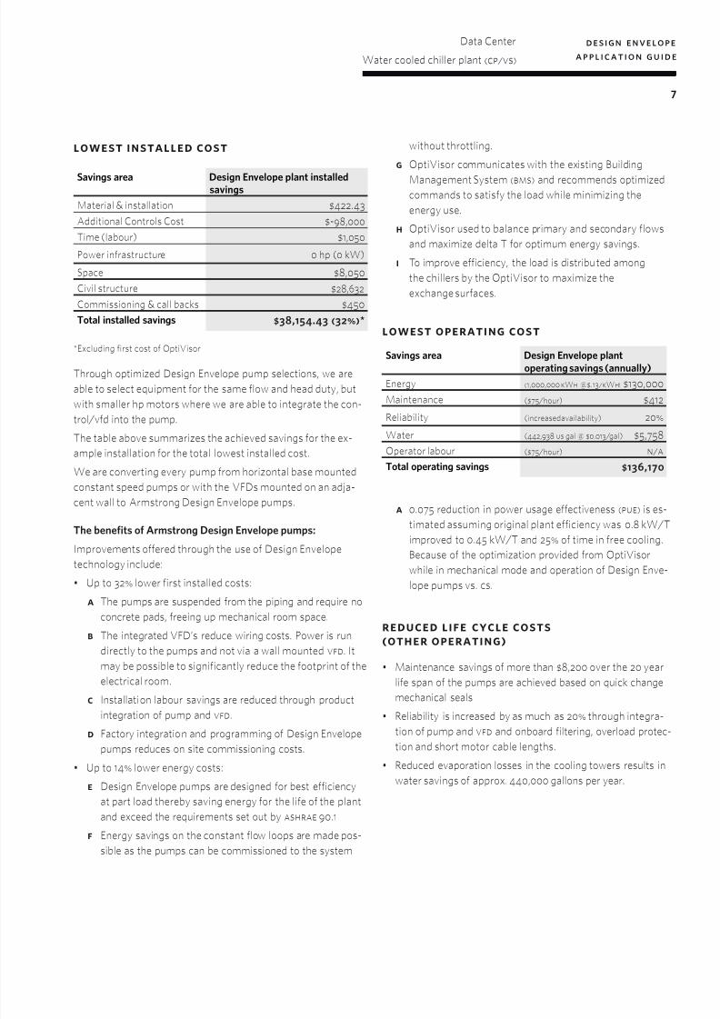
lowest installed cost
*Excluding first cost of OptiVisor
Through optimized Design Envelope pump selections, we are
able to select equipment for the same flow and head duty, but
with smaller hp motors where we are able to integrate the con-
trol/vfd into the pump.
The table above summarizes the achieved savings for the ex-
ample installation for the total lowest installed cost.
We are converting every pump from horizontal base mounted
constant speed pumps or with the VFDs mounted on an adja-
cent wall to Armstrong Design Envelope pumps.
The benefits of Armstrong Design Envelope pumps:Improvements offered through the use of Design Envelope
technology include:
• Up to 32% lower first installed costs:
a The pumps are suspended from the piping and require no
concrete pads, freeing up mechanical room space.
b The integrated VFD’s reduce wiring costs. Power is run
directly to the pumps and not via a wall mounted vfd. It
may be possible to significantly reduce the footprint of the
electrical room.
c Installation labour savings are reduced through product
integration of pump and vfd.
d Factory integration and programming of Design Envelope
pumps reduces on site commissioning costs.
• Up to 14% lower energy costs:
e Design Envelope pumps are designed for best efficiency
at part load thereby saving energy for the life of the plant
and exceed the requirements set out by ashrae 90.1
f Energy savings on the constant flow loops are made pos-
sible as the pumps can be commissioned to the system
without throttling.
g OptiVisor communicates with the existing Building
Management System (bms) and recommends optimizedcommands to satisfy the load while minimizing the
energy use.
h OptiVisor used to balance primary and secondary flows
and maximize delta T for optimum energy savings.
i To improve efficiency, the load is distributed among
the chillers by the OptiVisor to maximize the
exchange surfaces.
lowest operating cost
a 0.075 reduction in power usage effectiveness (pue) is es-
timated assuming original plant efficiency was 0.8 kW/T
improved to 0.45 kW/T and 25% of time in free cooling.
Because of the optimization provided from OptiVisor
while in mechanical mode and operation of Design Enve-
lope pumps vs. cs.
reduced life cycle costs(other operating)
• Maintenance savings of more than $8,200 over the 20 year
life span of the pumps are achieved based on quick change
mechanical seals
• Reliability is increased by as much as 20% through integra-tion of pump and vfd and onboard filtering, overload protec-
tion and short motor cable lengths.
• Reduced evaporation losses in the cooling towers results in
water savings of approx. 440,000 gallons per year.
Savings area Design Envelope plant installedsavings
Material & installation $422.43
Additional Controls Cost $-98,000
Time (labour) $1,050
Power infrastructure 0 hp (0 kW)
Space $8,050
Civil structure $28,632
Commissioning & call backs $450
Total installed savings $38,154.43 (32%)*
Savings area Design Envelope plantoperating savings (annually)
Energy (1,000,000 kWh @$.13/kWh) $130,000
Maintenance ($75 /hour) $412
Reliability (increased availability) 20%
Water (442,938 us gal @ $0.013 /gal) $5,758
Operator labour ($75 /hour) n/a
Total operating savings $136,170
7/21/2019 9 573 WaterCooledChillerPlantCPVS
http://slidepdf.com/reader/full/9-573-watercooledchillerplantcpvs 8/10
design envelope
application guide
Data Center
Water cooled chiller plant (cp/vs)
8
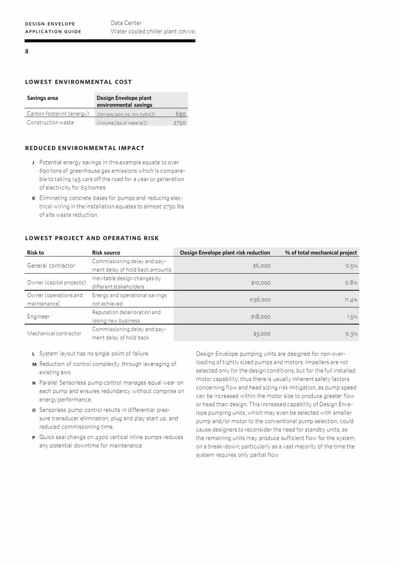
lowest environmental cost
reduced environmental impact
j Potential energy savings in this example equate to over
690 tons of greenhouse gas emissions which is compara-
ble to taking 145 cars off the road for a year or generation
of electricity for 63 homes.
k Eliminating concrete bases for pumps and reducing elec-trical wiring in the installation equates to almost 2750 lbs
of site waste reduction.
lowest project and operating risk
l System layout has no single point of failure
m Reduction of control complexity through leveraging of
existing bms
n Parallel Sensorless pump control manages equal wear on
each pump and ensures redundancy without comprise on
energy performance.
o Sensorless pump control results in differential pres-
sure transducer elimination, plug and play start up, and
reduced commissioning time.
p Quick seal change on 4300 vertical inline pumps reduces
any potential downtime for maintenance.
Design Envelope pumping units are designed for non-over-
loading of tightly sized pumps and motors. Impellers are not
selected only for the design conditions, but for the full installed
motor capability; thus there is usually inherent safety factors
concerning flow and head sizing risk mitigation, as pump speed
can be increased within the motor size to produce greater flowor head than design. This increased capability of Design Enve-
lope pumping units, which may even be selected with smaller
pump and/or motor to the conventional pump selection, could
cause designers to reconsider the need for standby units, as
the remaining units may produce sufficient flow for the system,
on a break-down; particularly as a vast majority of the time the
system requires only partial flow.
Savings area Design Envelope plantenvironmental savings
Carbon footprint (energy) (ton ghg [90% ng, 10% hydro]) 690
Construction waste (Volume [lbs of material]) 2750
Risk to Risk source Design Envelope plant risk reduction % of total mechanical project
General contractorCommissioning delay and pay-
ment delay of hold back amounts$6,000 0.5%
Owner (capital projects)Inevitable design changes by
different stakeholders$10,000 0.8%
Owner (operations andmaintenance)
Energy and operational savingsnot achieved
$136,000 11.4%
EngineerReputation deterioration and
losing new business$18,000 1.5%
Mechanical contractorCommissioning delay and pay-
ment delay of hold back$3,000 0.3%

7/21/2019 9 573 WaterCooledChillerPlantCPVS
http://slidepdf.com/reader/full/9-573-watercooledchillerplantcpvs 9/10
design envelope
application guide
Data Center
Water cooled chiller plant (cp/vs)
9
process & instrumentation diagr am
7/21/2019 9 573 WaterCooledChillerPlantCPVS
http://slidepdf.com/reader/full/9-573-watercooledchillerplantcpvs 10/10
t m
b u f f a l o
t o r o n t o
m a n c h e s t e r
b a n g a l o r e
s h a n g h a i
arms tro n gflui dtech n o lo gy.co m
#59, first floor, 3rd main
margosa road, malleswaram
bangalore, india
560 003
+91 (0) 80 4906 3555
wolverton street
manchester
united kingdom
m11 2et
+44 (0) 8444 145 145
93 east avenue
north tonawanda, new yorku.s.a.
14120-6594
+1 716 693 8813
23 bertrand avenue
toronto, ontario
canada
m1l 2p3
+1 416 755 2291
no. 1619 hu hang road, xi du township
feng xian district, shanghai
p.r.c.
201401
+86 21 3756 6696
arms tro n g flui d t ech n o lo gy
established 1934
b i r m i n g h a m
heywood wharf, mucklow hill
halesowen, west midlands
united kingdom
b62 8dj
+44 (0) 8444 145 145


