714 IEEE TRANSACTIONS ON POWER DELIVERY, VOL. 28, NO. 2, APRIL 2013
A Fault Detection Technique for theSeries-Compensated Line During
Power SwingParesh Kumar Nayak, Ashok Kumar Pradhan, Senior Member, IEEE, and Prabodh Bajpai, Member, IEEE
Abstract—A distance relaying scheme is susceptible to powerswing. To avoid unintended trip operation during such conditions,a power swing blocking function is utilized in distance relays. How-ever, if a fault occurs during power swing, the relay should detectthe fault and trip as soon as possible. The detection of fault in aseries-compensated line during the power swing is further com-plicated due to complex transients produced by series capacitorand the metal–oxide varistor (MOV) protecting it. This paper pro-poses a negative-sequence current-based technique for detectingall types of faults during the power swing in a series-compensatedline. The technique is tested for different series-compensated sys-tems including a 9-bus 3-machine power system. Different types offaults: symmetrical, asymmetrical, and high resistance occurringduring the power swing are simulated through EMTDC/PSCADto test the algorithm. The method is compared with available tech-niques and found to be accurate and fast.
Index Terms—Digital relaying, distance protection, fault detec-tion, power swing, series compensation.
I. INTRODUCTION
R ECENT regulatory developments, increased electricitydemand, and restrictions on building new transmission
lines result in enhanced transmission-line loading and neces-sitate optimized operation of transmission networks. To fulfillsuch requirements, the inclusion of a series capacitor in longtransmission lines is increasing day by day. However, a seriescapacitor in a line introduces protection problems [1]–[5].Power system at steady operation maintains a balance be-
tween the generation and load. System disturbances, such asline switching following the fault, generator disconnection, andswitching ON/OFF large loads cause oscillations in rotor anglesamong generators and can result in severe power-flow swings.As a consequence, the apparent impedance seen by a distancerelay may fall within its operating zone. This may be misinter-preted as a fault and the relay would trip the line unnecessarily.To ensure stability, the power-swing blocking (PSB) function isintegrated with the distance relay to block it during the powerswing [6]. However, if a fault occurs during the power swing,
Manuscript received January 27, 2012; revised May 21, 2012 and October05, 2012; accepted November 26, 2012. Date of publication January 03, 2013;date of current version March 21, 2013. Paper no. TPWRD-00099-2012.The authors are with the Department of Electrical Engineering, Indian Insti-
the relay must detect the fault and operate quickly. The detec-tion of faults in a series-compensated line during power swingsis more challenging due to the generation of different frequencycomponents in the fault signals which depend on the fault lo-cation, fault type, the level of compensation, and functioningof MOV [16]. This causes the apparent impedance seen by therelay to oscillate which imposes difficulty to distinguish faultsfrom the power swing. This paper proposes a technique for de-tecting faults in a series-compensated line during the powerswing.There are numerous techniques available to detect fault
during the power swing for transmission lines without seriescompensation [7]–[13]. A technique based on the magnitudeof swing-center voltage (SCV) and its rate is proposed todistinguish faults from the power swing [7]. A method basedon monitoring the voltage phase angle at the relay location isavailable for detecting high-impedance ground faults duringthe power swing [8]. A fault detector using superimposedcomponents of current is proposed in [9]. The rate of change ofresistance estimated at the relay location is used to distinguishfaults from the power swing [10]. In [11], a cross-blockingscheme on the basis of the derivative of the three-phase activeand reactive power is proposed to detect symmetrical faultsduring the power swing. A symmetrical fault detector is pro-posed based on the relative presence of decaying dc in thecurrent waveforms during the power swing [12]. A methodbased on adaptive neuro-fuzzy inference system is proposedin [13]. This method needs a large number of training patternsto be generated and has limited performance to distinguishfaults from fast power swing. The evaluation and perfor-mance comparison of different power swing detectors for aseries-compensated line has been studied in [14]. In [15], afault detection technique for a series-compensated line duringthe power swing is proposed using negative-sequence currentand is tested for an SMIB system.Techniques available to detect the fault during the power
swing in uncompensated lines find limitations in the presenceof series compensation due to the nonlinear functioning ofthe series capacitor combination. Though power swing is abalanced phenomenon, a small value of negative-sequencecomponent of current is observed as the conventional phasorestimation technique does not consider the signal modulation.During unbalanced faults, the negative-sequence componentsbecome significant and due to transients in current signals in theinitial period, a negative sequence component is noticed evenfor three-phase faults. To discriminate the faults during swing
NAYAK et al.: FAULT DETECTION TECHNIQUE FOR SERIES-COMPENSATED LINE 715
Fig. 1. Single-line diagram of the 400-kV power system.
in a series-compensated line, a cumulative sum (CUSUM)of change in the magnitude of the negative-sequence-cur-rent-based approach is proposed in this paper. The CUSUMtest is being employed widely as a technique for detectingabrupt changes in various fields [18]. The performance of thealgorithm is tested for numerous cases for an SMIB system anda 9-bus system simulated with EMTDC/PSCAD and found tobe accurate and fast. The method is compared with availablefault detection techniques.
II. FAULT DETECTION CHALLENGES DURING THE POWERSWING IN SERIES-COMPENSATED LINES
Series compensation imposes protection problems and are re-lated to the level of compensation, location, and the operationof its overvoltage protection devices like MOV and air gap. Theuse of series capacitors in transmission lines results in variousspecial phenomena, such as voltage/current inversion, subhar-monic oscillations, and transients caused by theMOV operationduring the fault period [1]–[5].The detection of the fault during the power swing in anMOV-
protected series-compensated line is difficult. The pattern of thefault current during such a period depends on the operation ofthe MOV. This imposes difficulty for the existing phasor esti-mation techniques to distinguish faults from the power swing.During the power swing when faults occur in a series-compen-sated line at the far end of a line or at a power angle close to180 or with high fault resistance, themagnitude of the fault cur-rent produced may be less than or at par with the swing current.Such a low fault current may prevent the capacitor bypassing.The presence of the series capacitor in the fault circuit results insubsynchronous oscillations which will cause variation in theestimated impedance. This also creates difficulty to distinguishfaults from the power swing.In order to demonstrate the fault detection issues during
power swing in a series-compensated line, a test system [19]shown in Fig. 1 is considered. Both Line-1 and Line-2 are40% compensated and the capacitors are placed at the relayend and the protection scheme of each series capacitor in-cluding an MOV as shown. The system details are providedin Appendix A. The system with the distributed line modelis simulated using EMTDC/PSCAD. The power angle hererefers to the angle between the voltages at buses M and N. Thedistance relay R for breaker B1 is considered for the study.A three-phase fault is created at the middle of Line-2 at 0.6
Fig. 2. (a) Current and (b) voltage waveforms of phase-a at the relay bus duringthe power swing.
Fig. 3. Current waveforms at the relay bus for a three-phase fault during thepower swing at 2.542 s at locations of (a) 64 km and (b) 240 km.
s and cleared at 0.7 s by opening breakers B3 and B4. Thiscauses a power swing condition in Line-1 and is observed bythe relay R. During this condition, phase-a current and voltagewaveforms are shown in Fig. 2(a) and (b), respectively. Fromthe figure, it is clearly observed that during swing current andvoltage waveforms are modulated with the swing frequency.As a result, the traditional fault detection techniques, such asthe sample-to-sample or cycle-to-cycle comparison of current(or voltage) signals [20] cannot be reliable during the powerswing.To study the variation in the current waveforms for faults
during the power swing, a three-phase fault is created at 2.542 sfor two different fault locations (64 and 240 km) from the relaybus in line-1 following the removal of line-2. The correspondingcurrent waveforms are shown in Fig. 3(a) and (b), respectively.It is clearly observed from Fig. 3(a) that in the case of the
fault being close to the relay, the current level as seen from theplot is higher than the swing current which causes the MOVto operate. As a result, in most portions of the fault, the seriescapacitor is bypassed and no oscillation is observed in the faultcurrent. However, in case of a fault at the far end [Fig. 3(b)],the level of fault current is lower than the swing current whichdoes not enableMOV conduction and results in subsynchronous
716 IEEE TRANSACTIONS ON POWER DELIVERY, VOL. 28, NO. 2, APRIL 2013
Fig. 4. (a) Three-phase current waveforms. (b) Current magnitude. (c) Nega-tive- and positive-sequence current magnitude for an ag-fault during the powerswing.
oscillation in the current waveforms. These issues result in morecomplexity to identify the fault.
III. PROPOSED FAULT DETECTION TECHNIQUE
The power swing is a balanced phenomenon [12], but a smallpercentage of negative-sequence components of current isfound due to signal modulation and the related phasor computa-tion technique. For unbalanced faults during the power swing, asignificant amount of negative-sequence current is observed. Incase of a three-phase fault during the power swing, negative-se-quence current is observed at the initial period of the fault dueto transients in the current signals and in the subsequent perioddue to the presence of modulated frequency components by thepower swing.To observe the variation of during swing and fault, an
ag-fault with a fault resistance of 0.1 and a three-phase faultare created at 3.51 s during the powerswing at a distance of 64 km from relay R toward bus N of Fig. 1,and the corresponding results are provided in Figs. 4 and 5, re-spectively. In case of the ag-fault, phase-a current only exceedsthe swing current as a result MOV of only phase-a operates.For the three-phase fault, MOVs of all three phases conduct.Figs. 4(c) and 5(c) clearly show the low value of that ispresent during the power swing. From Fig. 4(c), it is evidentthat during the ag-fault, becomes significant and oscillatesdue to modulating frequency components in the fault signals.From Fig. 5(c), it is observed that during the three-phase fault,
Fig. 5. (a) Three-phase current waveforms. (b) Current magnitude. (c) Nega-tive- and positive-sequence current magnitude for a three-phase fault during thepower swing.
varies rapidly at the inception of the fault due to the ini-tial transient and following that, it has a low value due to signalmodulation by the swing.It is evident from the previous discussion that negative-se-
quence current is available in the computation process duringthe swing. But with a small amount of remaining during theswing condition, a change in the magnitude of the negative-se-quence current -based technique suits the purpose. Witha suitable threshold, the cumulative sum of the -basedtechnique is selected in this paper for the fault detectionduring swing. CUSUM is a versatile technique used for abruptchange detection in various fields [18]. It is to be noted that theCUSUM-based approach is applied for transmission-line faultdetection using sampled values of the current signal [20] andhas limitations due to uneven variation in sample-to-samplemagnitude difference of current during power swing. In thispaper, CUSUM is applied to obtain a good index for faultdetection during the power swing where a change in nega-tive-sequence current is being used as the input signal. Thecomputation steps for the method are provided
(1)
where is the negative-sequence current; and ;and and are the phase currents.A derived signal is obtained as
(2)
For , the proposed CUSUM test is expressed as
(3)
NAYAK et al.: FAULT DETECTION TECHNIQUE FOR SERIES-COMPENSATED LINE 717
where the index represents the test statistics and is the driftparameter in it. A fault is registered if
(4)
where h is a constant and should be ideally zero. In (3), pro-vides the low-pass filtering effect and influences the perfor-mance of the detector. When , the value increasesby a factor of the difference between and . With further cur-rent samples available, the CUSUM process provides an easyway to decide on the fault situation by applying (4). After eachfault detection index, is reset to zero. For only the swing sit-uation, will be zero as . For the technique that isbased on the negative-sequence component for the single-poletripping condition, the method will also not be affected.The selection of and h is important for determining the
performance of the algorithm. It is already demonstrated thatthough the power swing is a balanced phenomenon, a smallamount of negative-sequence component of current is observedin the phasor extraction process which increases slowly withan increase of swing cycle slip frequency. In the proposedCUSUM-based fault detection technique, the value of is setto make 0 during swing (both stable and unstable) whichfinally helps to maintain the fault detector index 0. In thispaper, the setting of 0.05 serves the purpose for a powerswing with a slip frequency of 10 Hz. The slip frequency for atypical power system is within 7 Hz [19].The value of h is set such that the algorithm can maintain the
balance between dependability versus security and speed versusaccuracy requirements of the relaying scheme. In this paper, thevalue of h is set at 0.5, considering all extreme fault situationsduring the power swing, for example, high resistance faults oc-curring at the far end of the line when is close to 180 (thechange in magnitude of fault current is low; dependability issue)as well as nonfault situations such as load change and capac-itor switching (security issue) such that the proposed techniquecan distinguish faults from other events correctly. The proposedmethod is based on the CUSUM approach and, therefore, a dis-tinctly much higher index value is obtained during the fault.
IV. RESULTS
The algorithm for fault detection is tested for different condi-tions including balanced and unbalanced faults, high resistancefaults, close-in faults, and single pole-open condition during thepower swing. Using EMTDC/PSCAD with distributed param-eter line model data was generated. The inputs to the relay arefed from the secondary of a current transformer with a turnsratio of 1000:5. The nonlinear CT model is considered in thesimulations. A least-square technique with decaying dc compo-nent also in the model is used to estimate the fundamental com-ponent. For each phasor computation, a window of one-cycledata samples was considered. The data-sampling rate was main-tained at 1 kHz for the 50-Hz power system. Sequence com-ponents were estimated considering phase-a as reference. Theconvention used in this paper is such that the output of the algo-rithm should be ‘1’ for fault and ‘0’ for the no-fault situation.
Fig. 6. Performance during the line-to-ground fault.
During the power swing when is close to 180 , the currentsand voltages reach their maximum and minimum, respectively.If a fault occurs at that instant, the change in current and voltagesignals will be insignificant. As a result, the detection of faultsduring close to 180 is a much difficult issue. In order to testthe algorithm at critical conditions, all faults are created at afault inception time of 2.542 s which corresponds toand a slip frequency of 4 Hz. As mentioned in Section II, faultsoccurring far away from the series capacitor produce currentmagnitude less than the swing current when MOV does not op-erate. At this condition, the presence of series capacitor in thecircuit during the fault period results in subsynchronous oscil-lations which complicate the fault detection process. In orderto test the proposed technique for far-end faults, all faults arecreated at 240 km from the capacitor toward bus which cor-responds to 75% of the line length.
A. Line-to-Ground Fault in the Series-Compensated Line
The algorithm is tested for a line-to-ground fault of ag-typewith a fault resistance of 0.1 initiated at 2.542 s 175at a distance of 240 km from the relay location, and the resultsare shown in Fig. 6. With the fault being unbalanced, theobserved during the fault is significant and oscillating in naturedue to signal modulation. The index , which decides the outputof the algorithm, is zero before the inception of the fault andafter that its value grows. The output “1” clearly shows that thefault is detected after 5 ms of fault initiation.
B. Line-to-Ground Fault With High Fault Resistance
The detection of high-resistance ground faults during thepower swing with a large value of prefault current (i.e., near
is a difficult issue as the change in current is notsignificant. To test the technique, a line-to-ground fault ofan ag-type with fault resistance 100 is initiated at 2.542 s
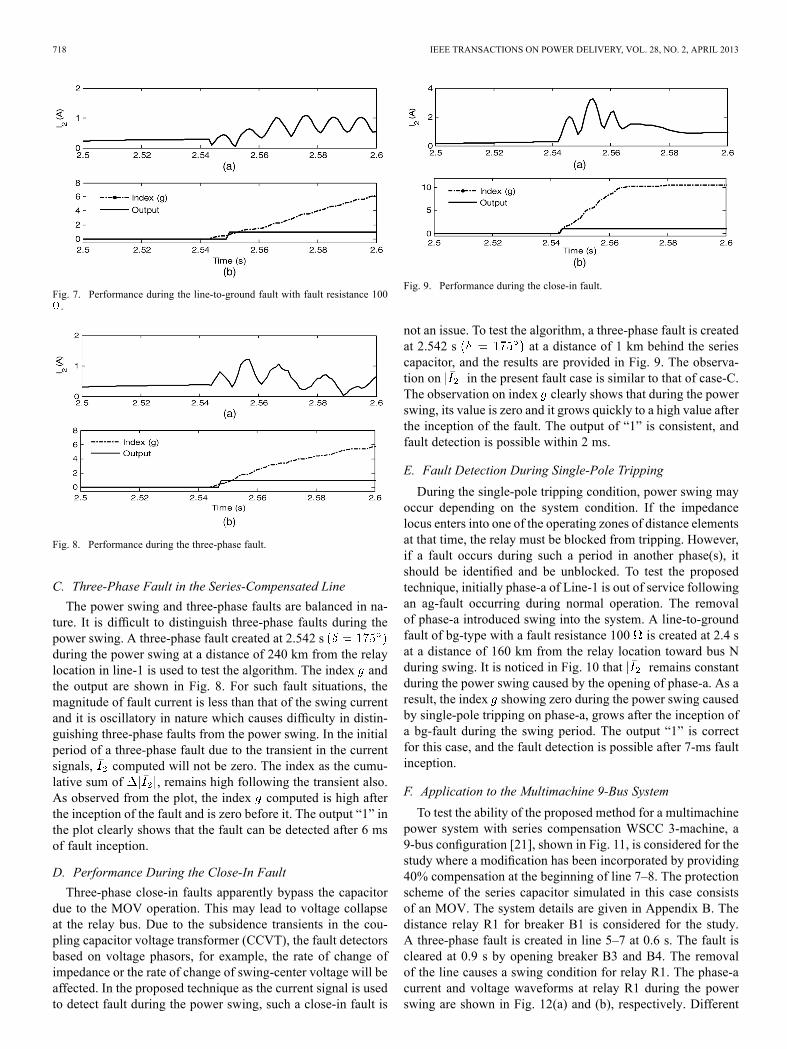
during the power swing at a distance of 240 kmfrom the relay location, and the results are shown in Fig. 7. It isclearly observed that the presence of high fault path resistancereduces compared to case-A during the fault, but thepattern of current is unaltered. The index grows but with alittle less of a rate than case-A. Since the proposed method isa CUSUM-based approach, the output “1” shows correct faultdetection after 8 ms of fault initiation.
718 IEEE TRANSACTIONS ON POWER DELIVERY, VOL. 28, NO. 2, APRIL 2013
Fig. 7. Performance during the line-to-ground fault with fault resistance 100.
Fig. 8. Performance during the three-phase fault.
C. Three-Phase Fault in the Series-Compensated Line
The power swing and three-phase faults are balanced in na-ture. It is difficult to distinguish three-phase faults during thepower swing. A three-phase fault created at 2.542 sduring the power swing at a distance of 240 km from the relaylocation in line-1 is used to test the algorithm. The index andthe output are shown in Fig. 8. For such fault situations, themagnitude of fault current is less than that of the swing currentand it is oscillatory in nature which causes difficulty in distin-guishing three-phase faults from the power swing. In the initialperiod of a three-phase fault due to the transient in the currentsignals, computed will not be zero. The index as the cumu-lative sum of , remains high following the transient also.As observed from the plot, the index computed is high afterthe inception of the fault and is zero before it. The output “1” inthe plot clearly shows that the fault can be detected after 6 msof fault inception.
D. Performance During the Close-In Fault
Three-phase close-in faults apparently bypass the capacitordue to the MOV operation. This may lead to voltage collapseat the relay bus. Due to the subsidence transients in the cou-pling capacitor voltage transformer (CCVT), the fault detectorsbased on voltage phasors, for example, the rate of change ofimpedance or the rate of change of swing-center voltage will beaffected. In the proposed technique as the current signal is usedto detect fault during the power swing, such a close-in fault is
Fig. 9. Performance during the close-in fault.
not an issue. To test the algorithm, a three-phase fault is createdat 2.542 s at a distance of 1 km behind the seriescapacitor, and the results are provided in Fig. 9. The observa-tion on in the present fault case is similar to that of case-C.The observation on index clearly shows that during the powerswing, its value is zero and it grows quickly to a high value afterthe inception of the fault. The output of “1” is consistent, andfault detection is possible within 2 ms.
E. Fault Detection During Single-Pole Tripping
During the single-pole tripping condition, power swing mayoccur depending on the system condition. If the impedancelocus enters into one of the operating zones of distance elementsat that time, the relay must be blocked from tripping. However,if a fault occurs during such a period in another phase(s), itshould be identified and be unblocked. To test the proposedtechnique, initially phase-a of Line-1 is out of service followingan ag-fault occurring during normal operation. The removalof phase-a introduced swing into the system. A line-to-groundfault of bg-type with a fault resistance 100 is created at 2.4 sat a distance of 160 km from the relay location toward bus Nduring swing. It is noticed in Fig. 10 that remains constantduring the power swing caused by the opening of phase-a. As aresult, the index showing zero during the power swing causedby single-pole tripping on phase-a, grows after the inception ofa bg-fault during the swing period. The output “1” is correctfor this case, and the fault detection is possible after 7-ms faultinception.
F. Application to the Multimachine 9-Bus System
To test the ability of the proposed method for a multimachinepower system with series compensation WSCC 3-machine, a9-bus configuration [21], shown in Fig. 11, is considered for thestudy where a modification has been incorporated by providing40% compensation at the beginning of line 7–8. The protectionscheme of the series capacitor simulated in this case consistsof an MOV. The system details are given in Appendix B. Thedistance relay R1 for breaker B1 is considered for the study.A three-phase fault is created in line 5–7 at 0.6 s. The fault iscleared at 0.9 s by opening breaker B3 and B4. The removalof the line causes a swing condition for relay R1. The phase-acurrent and voltage waveforms at relay R1 during the powerswing are shown in Fig. 12(a) and (b), respectively. Different
NAYAK et al.: FAULT DETECTION TECHNIQUE FOR SERIES-COMPENSATED LINE 719
Fig. 10. Performance during single-pole tripping.
Fig. 11. Single-line diagram of the modified WSCC 9-bus system.
Fig. 12. (a) Current and (b) voltage waveforms of phase-a at the relay busduring the power swing.
faults are simulated on line 7–8 to test the algorithm. The resultsof only two representative test cases are included below.1) Case-1: Line-to-Ground Fault: An ag-fault with a fault
resistance of 0.1 is created during the power swing on line7–8 at a distance of 160 km from the relay location at 2.3 s.From the result in Fig. 13, the growth of in the present faultcase is similar to that of case-A of the SMIB system. The indexincreases to a higher value at the inception of the fault and
Fig. 13. Performance during the line-to-ground fault.
Fig. 14. Performance during the double-line-to-ground fault.
the technique is able to detect the fault within half-a-cycle of itsinception.2) Case-2: Double Line-to-Ground Fault: The performance
of the algorithm for a double-line-to-ground fault of abg-typewith a ground fault resistance of 0.1 is created at 2.3 s on line7–8 during the power swing at a distance of 160 km from therelay location as shown in Fig. 14. It is observed from Fig. 14that the growth of is slightly faster than that of the ag-faultexplained in Case-I which causes the index to grow quicklyafter faul inception. The output “1” shows that such a fault canbe detected after 5 ms of fault inception. The output is alsoconsistent.Apart from critical fault conditions as demonstrated before,
the proposed technique has also been tested for faults at differentfault inception time, fault locations, and different prefault load-ings in the presence and absence of series compensation in theline during the power swing. The performance of the proposedalgorithm is found to be accurate for all of these conditions. It isalso found that the algorithm is unaffected for the operation ofair gap of the series capacitor for certain faults during the powerswing. The performance of the proposed technique for nonfaultsituations such as load change, capacitor switching, and signalscontaining noise are also evaluated and found to be satisfactory.
V. COMPARATIVE ASSESSMENT OF THE PROPOSED TECHNIQUE
There are several techniques available to detect the faultduring the power swing and applied to uncompensated lines
720 IEEE TRANSACTIONS ON POWER DELIVERY, VOL. 28, NO. 2, APRIL 2013
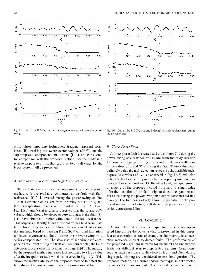
Fig. 15. Current Ia, R, SCV, Isup and Index (g) for an ag-fault during the powerswing.
only. Three important techniques: tracking apparent resis-tance (R), tracking the swing center voltage (SCV), and thesuperimposed components of current are consideredfor comparison with the proposed method. For the study in aseries-compensated line, the results of two fault cases for the9-bus system will be presented.
A. Line-to-Ground Fault With High Fault Resistance
To evaluate the comparative assessment of the proposedmethod with the available techniques, an ag-fault with faultresistance 100 is created during the power swing on line7–8 at a distance of 64 km from the relay bus at 2.3 s, andthe corresponding results are provided in Fig. 15. FromFig. 15(b) and (c), it is clearly observed that the R and SCVvalues, which should be closed to zero throughout the fault [8],[11], have obtained a higher value due to the fault resistance.This imposes difficulty to set threshold values to discriminatefaults from the power swing. These observations clearly showthat methods based on tracking R and SCV will find limitationto detect asymmetrical faults during the power swing in aseries-compensated line. The slow rise of superimposed com-ponents of current during the fault will obviously delay the faultdetection process which is evident from Fig. 15(d). The indexby the proposed method increases fast from zero to a high valueafter the inception of fault which is observed in Fig. 15(e). Thisshows the relative ability of the proposed method to detect thefault during the power swing in a series-compensated line.
Fig. 16. Current Ia, R, SCV, Isup and Index (g) for a three-phase fault duringthe power swing.
B. Three-Phase Fault
A three-phase fault is created at 2.3 s on lines 7–8 during thepower swing at a distance of 240 km from the relay locationfor comparison purposes. Fig. 16(b) and (c) shows oscillationsin the values of R and SCV during the fault. These values willdefinitely delay the fault detection process by the available tech-niques. Low values of , as observed in Fig. 16(d), will alsodelay the fault detection process by the superimposed compo-nents of the current method. On the other hand, the rapid growthof index of the proposed method from zero to a high valueafter the inception of the fault helps to detect the symmetricalfault also during the power swing in a series-compensated linequickly. The two cases clearly show the potential of the pro-posed method in detecting fault during the power swing for aseries-compensated line.
VI. CONCLUSION
A novel fault detection technique for the series-compen-sated line during the power swing is presented in this paper.It uses a cumulative sum of change in the magnitude of neg-ative-sequence current to detect faults. The performance ofthe proposed algorithm is tested for balanced and unbalancedfaults for different series-compensated systems. Conditions,such as high-resistance fault, close-in fault, and fault duringsingle-pole tripping are considered to test the algorithm. Theproposed method, as a current-based technique, is not affectedby issues like close-in fault. The method is compared with
NAYAK et al.: FAULT DETECTION TECHNIQUE FOR SERIES-COMPENSATED LINE 721
available techniques and it is found that the method is accu-rate and fast in detecting faults during the power swing in aseries-compensated line.
APPENDIX A
System data for SMIB:Generator:600 MVA, 22 kV, 50 Hz, inertia constant 4.4 MW/MVA.
Transmission lines:Length of line 7–8 320 km., line 8–9 400 km., line7-5 310 km., line 5-4 350 km, line 6-4 350 km.,line 6–9 300 km.Loads
Load A 300 MW 100 MVAr.Load B 200 MW 75 MVAr.Load C 150 MW 75 MVAr.
The other parameters considered for generators, trans-formers, and transmission lines are the same as that providedfor SMIB in Appendix A.
REFERENCES
[1] R. J. Marttila, “Performance of distance relay mho elements on MOV-protected series-compensated lines,” IEEE Trans. Power Del., vol. 7,no. 3, pp. 1167–1178, Jul. 1992.
[2] H. J. Alture, J. B. Mooney, and G. E. Alexander, “Advances in seriescompensated line protection,” 2008. [Online]. Available: www.selinc.com/20081022, TP6340-01
[3] A. Newbould and I. A. Taylor, “Series compensated line protection:System modeling and relay testing,” in Proc. 4th Int. Conf. Develop.Power Protect., 1989, pp. 182–186.
[4] D. Novosel, A. G. Phadke, M. M. Saha, and S. Lindahl, “Problems andsolutions for microprocessor protection of series compensated lines,”in Proc. Conf. Develop. Power Syst. Protect., 1997, pp. 18–23.
[5] D. Novosel, B. Bachmann, D. Hart, Y. Hu, and M. M. Saha, “Algo-rithms for locating faults on series compensated lines using neural net-work and deterministic methods,” IEEE Trans. Power Del., vol. 11, no.4, pp. 1728–1735, Oct. 1996.
[6] IEEE Power System Relaying Committee of the IEEE Power Eng.Soc., Power Swing and Out-of-Step Considerations on TransmissionLine. Rep. PSRC WG D6, Jul. 2005. [Online]. Available: http://www.pes-psrc.org
[7] G. Benmouyal, D. Hou, and D. Tziouvaras, “Zero-setting power-swingblocking protection,” presented at the the 31st Annual Western Protec-tive Relay Conf., Spokane, WA, Oct. 2004.
[8] A. Mechraoui and D. W. P. Thomas, “A new principle for high resis-tance earth fault detection during fast power swings for distance pro-tection,” IEEE Trans. Power. Del., vol. 12, no. 4, pp. 1452–1457, Oct.1997.
[9] A. P. Apostolov, D. Tholomier, and S. H. Richards, “Superimposedcomponents based sub-cycle protection of transmission lines,” in Proc.IEEE Power Eng. Soc. Power Syst. Conf. Expo,, Oct. 2004, vol. 1, pp.592–597.
[10] Z. D. Gao and G. B. Wang, “A new power swing block in distanceprotection based on a microcomputer-principle and performance anal-ysis,” in Proc. Int. Conf. Adv. Power Syst. Control, Oper. Manage.,Hong Kong, China, Nov. 1991, vol. 2, pp. 843–847.
[11] X. Lin, Y. Gao, and P. Liu, “A novel scheme to identify symmetricalfaults occurring during power swings,” IEEE Trans. Power Del., vol.23, no. 1, pp. 73–78, Jan. 2008.
[12] S. Lotfifard, J. Faiz, and M. Kezunovic, “Detection of symmetricalfaults by distance relays during power swings,” IEEE Trans. PowerDel., vol. 25, no. 1, pp. 81–87, Jan. 2010.
[13] H. K. Zadeh and Z. Li, “A novel power swing blocking scheme usingadaptive neuro-fuzzy inference system,” Elect. Power Syst. Res., vol.78, pp. 1138–1146, 2008.
[14] A. Esmaeilian, A. Ghaderi, M. Tasdighi, and A. Rouhani, “Evaluationand performance comparison of power swing detection algorithms inpresence of series compensation on transmission lines,” in Proc. 10thInt. Conf. Environment Elect. Eng., May 8–11, 2011, pp. 1842–1848.
[15] P. K. Nayak, A. K. Pradhan, and P. Bajpai, “Detecting fault duringpower swing for a series compensated line,” presented at the Int. Conf.Energy, Autom., Signal, Bhubaneswar, Odisha, India, Dec. 28–30,2011.
[16] A. Y. Abdelaziz, A. M. Ibrahim, M. M. Mansour, and H. E. Talaat,“Modern approaches for protection of series compensated transmissionlines,” Elect. Power Syst. Res., vol. 75, pp. 85–98, 2005.
[17] T. S. Sidhu and M. Khederzadeh, “Series compensated line protectionenhancement by modified pilot relaying schemes,” IEEE Trans. PowerDel., vol. 21, no. 3, pp. 1191–1198, Jul. 2006.
[18] F. Gustafsson, Adaptive Filtering and Change Detection. New York:Wiley, 2000.
[19] S. M. Brahma, “Distance relay with out-of-step blocking functionusing wavelet transform,” IEEE Trans. Power Del., vol. 22, no. 3, pp.1360–1366, Jul. 2007.
[20] S. R. Mohanty, A. K. Pradhan, and A. Routray, “A cumulativesum-based fault detector for power system relaying application,”IEEE Trans. Power Del., vol. 23, no. 1, pp. 79–86, Jan. 2008.
[21] P. W. Sauer and M. A. Pai, Power System Dynamics and Stability.Upper Saddle River, NJ: Prentice-Hall, 1998.
Paresh Kumar Nayak received the B.E. degree inelectrical engineering from Sambalpur University,Sambalpur, India, in 2000, the M.Sc. degree in engi-neering from Indian Institute of Science, Bangalore,India, in 2003, and is currently pursuing the Ph.D.degree at Indian Institute of Technology, Kharagpur,India.He was an Engineer at Kirloskar Electric Com-
pany, Bangalore, India, in 2004 and was a Lecturer inthe Department of Electrical Engineering, KIIT Uni-versity, Odisha, India, from 2005 to 2009. His current
research interest is power system relaying.
722 IEEE TRANSACTIONS ON POWER DELIVERY, VOL. 28, NO. 2, APRIL 2013
Ashok Kumar Pradhan (M’94–SM’10) receivedthe Ph.D. degree in electrical engineering fromSambalpur University, Sambalpur, India, in 2001.Currently, he is with the Department of Elec-
trical Engineering, Indian Institute of Technology,Kharagpur, India, since 2002, where he is a Pro-fessor. His research interests includes power systemrelaying and monitoring.
Prabodh Bajpai (M’07) received the Ph.D. degreein electrical engineering from the Indian Institute ofTechnology (IIT), Kanpur, India.Currently, he is Assistant Professor in the Depart-
ment of Electrical Engineering at IIT, Kharagpur,India. His research interests include power systemrestructuring, renewable energy systems, solarphotovoltaic applications, and power systemoptimization.


![A DATA FOR - al-roomi.org€¦ · Appendix - A DATA FOR IEEE-30 BUS TEST SYSTEM The IEEE - 30 bus test system is shown in figure A.1.The system data is taken from references [3].The](https://static.documents.pub/doc/80x56/5e62f368bf9bd300695bce22/a-data-for-al-roomi-appendix-a-data-for-ieee-30-bus-test-system-the-ieee-.jpg)


