Electrical Drives Juha Pyrhönen, LUT, Department of Electrical Engineering 9.1 9. PERMANENT MAGNET SYNCHRONOUS MACHINE (PMSM) ......................................... 1 9.1 PMSM Configurations and Machine Parameters ................................................................ 2 9.2 Equivalent Circuit and Vector Diagram of a PMSM ........................................................... 8 9.3 Current Vector Control ...................................................................................................... 11 9.4 i d = 0 Control ...................................................................................................................... 11 9.5 Method for Minimizing the Stator Current ........................................................................ 14 9.6 Direct Flux Linkage and Torque Control PMSMDTC ...................................................... 17 9.7 Voltage Reserve and Power Factor .................................................................................... 19 9.8 On Speed and Position Sensorless Control Methods for PM Machines ............................ 25 9.9 Comparison of the Control Methods.................................................................................. 28 9. PERMANENT MAGNET SYNCHRONOUS MACHINE (PMSM) The development of high-quality permanent magnet materials into commercial production has encouraged several manufacturers to launch various permanent magnet synchronous machines (PMSM) into the market. Permanent magnet synchronous machines have been applied to servo drives for a long time already, and nowadays, there are quite large permanent magnet synchronous machines also in industrial use. In wind mill generators, the development has currently been in the direction of permanent magnet machines. In principle, vector control is required for controlling the PMSM. Previously, the poor qualities of the magnetic materials could considerably restrict the implementation of a motor control. For instance, due to the poor demagnetization characteristics of AlNiCo magnets, the so-called i d = 0 control was initially adopted in order to ensure the stability of the polarization. The properties of NdFeB and SmCo magnets instead allow also the use of demagnetizing current. Demagnetizing current is used in particular when aiming at the field weakening of a permanent magnet machine; however, a negative current aligned with the d-axis occurs also in the constant flux range, when aiming at a high power factor for the drive. The basic differences to the control principles of other AC motors are due to the magnetic properties of permanent magnets, and particularly to the fact that the permanent magnet material is a part of the magnetic circuit of the machine, and therefore has a significant influence on its reluctance. The relative permeability of permanent magnet materials r is close to one, and therefore the effective direct air gap of the PMSM often becomes very large. Thereby also the inductances of the machine – particularly in machines in which the magnets are located on the rotor surface – usually remain rather low. Another difference is that the direct synchronous inductance, when employing embedded magnets, can be less than the quadrature value, while the ratio is the opposite in a separately excited salient-pole synchronous machine. The field weakening of a PM machine has to be implemented by using a demagnetizing stator current. If the inductances are very low, the field weakening is not a rational option. In the surface magnet type servo motors, the per unit value of the synchronous inductance is typically in the range l d = 0.2−0.4. An adequate rotation speed range is often achieved by dimensioning the rated frequency of the machine to be sufficiently high. When employing embedded magnets, however, the inductances may be dimensioned so high that the rotation speed range can be expanded. Often when staying within the limits of the rated current, the upper limit remains at about double the rated speed at maximum. However, when applying field weakening, it should be borne in mind that the back emf caused by the permanent magnets is directly proportional to the rotation speed of the machine. If the demagnetizing current is lost for some reason, the inverter has to withstand this voltage undamaged; however, the danger of the breakdown of the inverter is obvious. The
Transcript
Electrical Drives Juha Pyrhönen, LUT, Department of Electrical Engineering
9.1
9. PERMANENT MAGNET SYNCHRONOUS MACHINE (PMSM) ......................................... 1 9.1 PMSM Configurations and Machine Parameters ................................................................ 2 9.2 Equivalent Circuit and Vector Diagram of a PMSM ........................................................... 8 9.3 Current Vector Control ...................................................................................................... 11 9.4 id = 0 Control ...................................................................................................................... 11 9.5 Method for Minimizing the Stator Current ........................................................................ 14 9.6 Direct Flux Linkage and Torque Control PMSMDTC ...................................................... 17 9.7 Voltage Reserve and Power Factor .................................................................................... 19 9.8 On Speed and Position Sensorless Control Methods for PM Machines ............................ 25 9.9 Comparison of the Control Methods .................................................................................. 28
9. PERMANENT MAGNET SYNCHRONOUS MACHINE (PMSM)
The development of high-quality permanent magnet materials into commercial production has encouraged several manufacturers to launch various permanent magnet synchronous machines (PMSM) into the market. Permanent magnet synchronous machines have been applied to servo drives for a long time already, and nowadays, there are quite large permanent magnet synchronous machines also in industrial use. In wind mill generators, the development has currently been in the direction of permanent magnet machines. In principle, vector control is required for controlling the PMSM. Previously, the poor qualities of the magnetic materials could considerably restrict the implementation of a motor control. For instance, due to the poor demagnetization characteristics of AlNiCo magnets, the so-called id = 0 control was initially adopted in order to ensure the stability of the polarization. The properties of NdFeB and SmCo magnets instead allow also the use of demagnetizing current. Demagnetizing current is used in particular when aiming at the field weakening of a permanent magnet machine; however, a negative current aligned with the d-axis occurs also in the constant flux range, when aiming at a high power factor for the drive. The basic differences to the control principles of other AC motors are due to the magnetic properties of permanent magnets, and particularly to the fact that the permanent magnet material is a part of the magnetic circuit of the machine, and therefore has a significant influence on its reluctance. The relative permeability of permanent magnet materials r is close to one, and therefore the effective direct air gap of the PMSM often becomes very large. Thereby also the inductances of the machine – particularly in machines in which the magnets are located on the rotor surface – usually remain rather low. Another difference is that the direct synchronous inductance, when employing embedded magnets, can be less than the quadrature value, while the ratio is the opposite in a separately excited salient-pole synchronous machine. The field weakening of a PM machine has to be implemented by using a demagnetizing stator current. If the inductances are very low, the field weakening is not a rational option. In the surface magnet type servo motors, the per unit value of the synchronous inductance is typically in the range ld = 0.2−0.4. An adequate rotation speed range is often achieved by dimensioning the rated frequency of the machine to be sufficiently high. When employing embedded magnets, however, the inductances may be dimensioned so high that the rotation speed range can be expanded. Often when staying within the limits of the rated current, the upper limit remains at about double the rated speed at maximum. However, when applying field weakening, it should be borne in mind that the back emf caused by the permanent magnets is directly proportional to the rotation speed of the machine. If the demagnetizing current is lost for some reason, the inverter has to withstand this voltage undamaged; however, the danger of the breakdown of the inverter is obvious. The
Electrical Drives Juha Pyrhönen, LUT, Department of Electrical Engineering
9.2
withstanding of DC link capacitors to voltages amounts typically only to 30–50 % above the rated voltage. As there are different alternatives for placing the permanent magnets in the rotor, it is not necessarily advisable to apply some general control method as such to all permanent magnet machines, but the control method has to be selected individually according to the machine configuration. The most control methods are based on the PMSM model in the rotor reference frame. These control methods require information on the rotor angle, and therefore, at least the speed data based on a pulse encoder as well as the definition of the initial rotor angle are required before start-up. In servo drives, the position feedback information given by the absolute encoder is often necessary. PM drives without a position feedback are a subject of extensive research activities. Several of the introduced methods are based on estimators, which require a plenty of calculation capacity. Quite a many studies have given good results when operating at least at moderate supply frequencies, however, operation close to zero speed is still somewhat problematic.
9.1 PMSM Configurations and Machine Parameters
The characteristics of a permanent magnet machine are highly dependent on the rotor structure. The rotor can be implemented in various ways. When employing the modern permanent magnet materials, the rotor can be constructed even completely without iron. In that case, the rotor frame is constructed for instance of aluminium, onto which the shaped permanent magnets are glued so that the sinusoidal flux density distribution is achieved in the air gap of the machine. An ironless rotor structure wastes permanent magnet material, since the magnetic circuit closes through air in the rotor side. Therefore, a thin steel rim, to which the magnets are attached, is employed (Fig. 9.1) The rim can be either a laminated structure, in which case the eddy current losses of the rotor remain very low, or a thin steel tube; however, in this case, there is a danger that the rotor warms up excessively due to the effect of the time harmonics of the stator. The inductances of a surface-magnet machine are very low, and therefore, a high switching frequency is required of a voltage source inverter in order for the currents of the machine to behave beautifully. The configuration is applied for instance to servo motors, of which a minimum inertia is required. The direct and quadrature inductance of the machine are in this case approximately equal, and the machine is thus a non-salient pole construction.
Electrical Drives Juha Pyrhönen, LUT, Department of Electrical Engineering
9.3
thin steel rim
magnets stator magnets stator
d
d
Figure 9.1 A low-inductance rotor configuration of a permanent magnet synchronous machine. The left-hand depiction illustrates a non-salient pole structure. In the right-hand structure, the steel rim is made as thin as possible on the d-axes to reduce the inertia of the machine. The flux diagram of the d-axis shows that there is a suitable path for the flux in this construction. The machine is magnetically slightly asymmetric, since there is a higher reluctance on the quadrature axis than there is on the direct axis. The adjustment of the machine inductances at a desired level can, if necessary, be implemented by iron parts; it is possible to mount pole shoes on the magnets, and thus to achieve the sinusoidal air gap flux density. When employing pole shoes, the magnets are well protected against both electric and magnetic stresses. In the assembly phase in particular, the pole shoes are very useful, as they protect the magnets from mechanical damages. The described configuration can be used in particular to implement multi-pole, slow-speed machines. A possible solid rotor configuration with pole shoes is illustrated in Figure 9.2. The solid pole shoes function also as a damper winding. When using pole shoes, it is advisable to shape them to produce a sinusoidal flux density distribution in the air gap. Thus, a smooth and quiet operation is achieved. The relative permeability of the present hard permanent magnet materials deviates slightly from one, and therefore, the characteristics of the material correspond quite closely to those of air. Hence the direct air gap of the machine becomes large. Due to the large air gap, the effect of the direct-axis armature reaction remains low, and the harmonics resulting form the small number slots per pole and per phase in the stator do not cause a significant torque ripple; this is a fact that brings certain special characteristics to the machine.
Electrical Drives Juha Pyrhönen, LUT, Department of Electrical Engineering
9.4
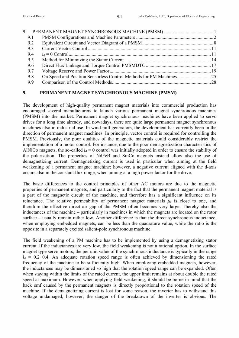
Figure 9.2 Cross-section of a solid pole shoe machine. In the construction, the stator back is excessively thick for a synchronous machine. The thickness required by the magnetic flux in the rotor is indicated by a dashed line; the rest of the rotor can be lightened for instance to reduce the weight of the construction. In solid pole machines, the magnetizing inductance remains relatively low, and therefore raising the rotation speed of the machine above the field weakening point requires a lot of current. An expensive permanent magnet material is used efficiently by the solid rotor. The magnetic flux flows almost completely through the air gap, and the magnetic leakage flux is very small. When using pole shoes, the permanent magnets are protected against demagnetization. Most of the demagnetizing forces do not travel through the magnets at all, but they are conducted elsewhere by the pole shoes. When employing pole shoes, the magnets can be rectangular, since the pole shoe can be shaped into the desired form. The rotors of permanent magnet machines can be constructed of electric sheet similarly as the rotors of asynchronous motors. There are various alternatives for a laminated rotor that bring the desired characteristics for the machine. Again, a stator of a permanent magnet machine equipped with a plate rotor is similar to the stator of an induction motor. The permanent magnets can be glued on the rotor surface similarly as in the case of a solid rotor. However, the magnets can also be embedded partly or completely into the rotor. When employing embedded magnets, the magnets can be mounted to the rotor in different positions. Alternatives for plate rotor structures are illustrated in Figure 9.3.
Electrical Drives Juha Pyrhönen, LUT, Department of Electrical Engineering
9.5
a) b)
c) d) Figure 9.3. Laminated rotor configurations of PM machines with embedded magnets. e) In the machines of the types illustrated in Figures 9.3 a-c, the physical air gap is approximately constant. The voltage induced to the stator of such a machine may include plenty of harmonics. Harmonics may thus occur in the torque causing vibration and noise. If an even torque is required of the machine, either the stator of rotor mmf has to be sinusoidal; otherwise the harmonics occurring at the same wave length in the air gap generate torque components of their own, and thus cause torque ripple. In order to be a competitive alternative especially among slow-speed drives, an even torque is required of the synchronous machine; the structures of Figures 9.3d and e aim at this target. In these constructions, the rotor plates are shaped to have poles that resemble the poles of a salient-pole machine; with these poles, a sinusoidal flux density is achieved in the air gap. Also these structures include reluctance differences that may produce especially a torque harmonic that occurs at a frequency that is six-fold the supply frequency. This can be avoided by skewing either in the stator or in the rotor. Machines with plate rotors have different characteristics depending on the rotor structure. The machines of illustrations a and c in Figure 9.3 are hybrid machines, which operate to some extent as synchronous reluctance machines without magnets. In these machines, some of the torque is produced by the different inductances in the direct and quadrature directions. The torque resulting from this inductance difference is known as the reluctance torque. By adding magnets to hybrid machines, the characteristics of the machines can be improved considerably when compared with
Electrical Drives Juha Pyrhönen, LUT, Department of Electrical Engineering
9.6
the respective characteristics of a reluctance machine. The start-up characteristics, efficiency and power factor of the machine in particular are notably better than in the reluctance machine. The construction applying rectangular magnets, illustrated in Figure 9.3c, requires flux barriers in the vicinity of the axis to prevent the flux from flowing through the axis. The configuration is mechanically quite challenging; furthermore, the structure provides a good path for the armature reaction, which is not always desirable. In the construction of Figure 9.3b, the magnets are embedded to the rotor surface. This construction provides a reluctance difference between the direct and quadrature axes. Due to the reluctance difference, the maximum torque produced by the machine is reached at a pole angle that is well above 90 degrees. The maximum torque is often reached by PM machines at a pole angle above 90 degrees, since the inductance in the q-direction is often slightly higher than in the d-direction. The structures of Figs. 9.3d and e have been developed to achieve a smooth and quiet operation at a low rotation speed. Since a PM machine can be constructed directly to operate at a low speed and to have a good efficiency and power factor, a mechanical gear can be omitted. Although the basic frequency of the machine can be set at a desired level by an inverter supply, it is still advisable to select the number of pole pairs to be relatively high. This is supported by the fact that the relative proportion of the thickness of the stator yoke is now reduced, which in turn enables the largest rotor diameter in a machine with a defined outer diameter. The number of slots per pole and per phase q can be one or even below that. Thus the stator mmf includes plenty of harmonics. Since the harmonics of the stator mmf are large, the rotor mmf has to be made sinusoidal in order to ensure that the machine runs steadily. The constructions of Figs- 9.3d and e may, however, involve torque ripples due to reluctance differences, which can yet be eliminated by a proper design. In machines with plate rotors, there occurs magnetic flux leakage, which can be reduced for instance by the leakage flux guides presented in Fig. 9.3a. The material of the flux guide can be air or some other poorly conducting material. Also the poles of Figures 9.3 d and e are designed to guide the flux into sinusoidal form, and simultaneously to reduce the magnetic leakage. The utilization factor of the magnets remains lower with embedded magnets than for instance with a salient pole machine, in which the flux generated by the magnet flows almost completely through the air gap. A plate rotor structure can be used to increase the air gap flux density by using two magnets per pole (cf. Fig. 9.3d), in which case the area in creases in proportion to the pole area. Simultaneously, however, the volume of the magnetic material increases resulting in a higher price of the machine. From the point of view of the manufacturers of small machines, plate rotors are often more interesting than solid rotors. The rotor plates can be manufactured on the same production line as the plates of asynchronous motors; this way, also the sheets that would otherwise be left over in the cutting process of the stator plates are now exploited, and thus the production costs can be reduced. Attaching the magnets to the rotor means naturally an additional phase in the production process. The constructions of Figs. 9.3 d and e aim at combining the advantages of a salient pole machine and the easy production of a plate rotor. Laminated rotor structures, which are clearly shaped to include pole shoes (cf. the types c and e in Fig. 9.3) can easily be equipped with damper windings that fit well into the pole shoes. The design enables the production of direct-on-line versions of the machines.
Electrical Drives Juha Pyrhönen, LUT, Department of Electrical Engineering
9.7
The per unit values of the PM machines deviate essentially from the pu values of traditional induction machines and synchronous machines in industrial use. While the pu value of the magnetizing inductance is typically above three for the induction machines, and it varies between one and two for the synchronous machines, the magnetizing inductance is only one tenth of these values for servo motors with surface-mounted magnets. The stator flux leakage is close to 0.1 for all of these machine types. The synchronous inductance of a servo motor with surface magnets is typically ca. ls = 0.3. Correspondingly, in multi-pole machines with embedded magnets, the synchronous inductance is typically of the scale lsd = 0.4−0.6 and lsq = 0.6−0.9. In PM machines with a large number of poles, the proportion of the stator flux leakage can increase excessively, and be up to a half of the total synchronous inductance. The load angle equation of a synchronous machine is an important subject of analysis also in the case of a PM machine. By applying phase pu values, the load equation can be written as
2sin
2sin3
qds
qd2sv
ds
PMvsv
LL
LLU
L
EUP . (9.1)
Correspondingly, we may write for the torque
2sin
2sin3
qd
qd2sv
d
PMvsv
LL
LLU
L
EUpT . (9.2)
If the machine is a non-salient pole one, the pull-out torque depends on the inverse of the synchronous inductance, and therefore, when aiming at a high torque production ability, the inductance should be low. This requirement is emphasized in PM machines, since the interior emf EPM of the machine cannot be altered similarly as the corresponding interior EF of synchronous machines by adjusting the field current. Often, due to practical reasons, the pu value of EPM has to be close to one. As the supply voltage is also one, the pu value of the synchronous inductance has to be selected at a value that is considerably below the value one. If the machine is a non-salient pole one, and ePM = us = 1, the synchronous inductance has to be ld = 0.625 at maximum, in order to achieve the commonly required 160 % pull-out torque. Thus, in order to achieve a good pull-out torque for PM machines, the synchronous inductances have to be relatively low. When using surface mounted magnets, this precondition is met quite easily. In machines with embedded magnets, the pu values approach one, and therefore the pu value of EPM cannot be increased considerably above one. Recently, fractional slot pole winding machines have entered the market as a novel PM machine configuration. In these machines, the number of slots per pole and per phase varies between 0.25−0.5. The machines are intended in particular as slow-speed direct drive machines producing maximum torque of a defined volume. By this method, it is possible to achieve the shortest end-windings and the stator back, and thus the maximum rotor diameter and length relative to the outer dimensions of the machine can be reached. Figure 9.4 presents fractional slot wound PM synchronous machines.
Electrical Drives Juha Pyrhönen, LUT, Department of Electrical Engineering
9.8
+B
-B
+C
-C+A
-A
+B
-B
+C
-C+ A
+ B
- A
- B
+ C
- C
+A
-A
Figure 9.4 Permanent magnet synchronous machines with single- and double-layer fractional slot windings Qs = 6, p = 2, q = 0.5. The best fractional slot wound machines produce a completely sinusoidal terminal voltage, and therefore an even torque can be achieved by a sinusoidal current supply. The control of this kind of a machine does not differ in principle from the control of any ordinary rotating-field PM machine.
9.2 Equivalent Circuit and Vector Diagram of a PMSM
Similarly as separately excited synchronous machines, the PM synchronous machines are usually treated in a dq reference frame fixed to the rotor, Figure 9.5. The equivalent circuit of the machine is almost the same as for a separately excited synchronous machine.
ud
idRs
q
d
Ls
Lmd
iPM
iD
RD
id+iD+iPM
LDmd
uq
iq Rsd
q
Ls
Lmq
iQ
RQ
iq+iQ
LQmq
iPM
Figure 9.5 Equivalent circuits of a PMSM in the d- and q-directions. The permanent magnet can be depicted by a current source iPM in the rotor circuit; in the magnetizing inductance, this current source produces the permanent magnet’s share of the air gap flux linkage PM = iPMLmd.
Electrical Drives Juha Pyrhönen, LUT, Department of Electrical Engineering
9.9
If also the damper windings are included in the model, the voltage equations of a PM machine differ from a separately excited synchronous machine only by the fact that the equation for the field winding is lacking. Thus, the voltage equations of the PM machine are given in the rotor reference frame in the familiar form:
u R itsd s sdsd
sq
d
d
, (9.3)
u R itsq s sq
sq
sd
d
d
, (9.4)
0 R itD D
Dd
d
, (9.5)
0 R itQ Q
Qd
d
. (9.6)
The flux linkage components in the equations are determined by the equations
sd sd sd md D PM L i L i , (9.7) sq sq sq mq Q L i L i , (9.8)
D md sd D D PM L i L i , (9.9) Q mq sq Q Q L i L i . (9.10)
The flux linkage PM of the permanent magnet can be considered to be generated by the field current
iLPM
PM
md
, (9.11)
now the definitions for the flux linkages do not deviate from the definitions of a separately excited synchronous machine. However, it is worth noticing that due to the saturation of the magnetizing inductance Lmd, iPM is not constant. The vector diagram of the PMSM is a modification of the vector diagram of a synchronous machine, Figure 9.6. Permanent magnets create the flux linkage PM of the permanent magnets in the stator winding.
Electrical Drives Juha Pyrhönen, LUT, Department of Electrical Engineering
9.10
x
y
dq
r
PM
s
is
lsdisd
lsqisq
us
s
isq
isd
s
Figure 9.6 Vector diagram of a PMSM. Stator reference frame (xy) and rotor reference frame (dq). At its nominal operating point, the machine operates as a motor us = 1, is = 1, s 12, lsd = lsq = 0.5. Load angle s 26.5. Power factor coss 0.98 It is quite common that there is no damping in the permanent magnet synchronous machines, in which case the flux linkages are simply written as
sd sd sd PM L i , (9.12) sq sq sq L i . (9.13)
There are also several other factors that cause damping in a machine: such a factor are for instance solid pole shoes. The resistivity of the magnets themselves is so high that their effect on the damping can be neglected. If the rotor frame is solid, it has a slight damping effect. A laminated rotor frame provides so few paths for the eddy currents that there seems in practice to be no damping either. All the other factors causing damping, the damper winding itself excluded, are difficult to estimate by any other means than measuring. For instance the short-circuit test at a rated current reveals in principle, what kind of a torque the damper winding produces. The presence of permanent magnets hampers all asynchronous measurements considerably. The torque equation according to the cross-field principle is basically the same as for separately excited synchronous machines. It can be written for a PMSM for instance in the form
T p i L L i i L i i L i ie PM sq mq md sd sq md D sq mq Q sd 3
2 . (9.14)
Torque is produced by the four terms determined according to the cross-field principle. The first term is the most important one, and it is in many PM machines the only term that depends on the flux linkage of permanent magnets and on the stator current perpendicular to the flux linkage. The second term resulting from the inductance difference is significant in machines in which the difference between the d-axis and q-axis inductances is large. The terms depending on the damper currents are significant only in transients and in machines in which damper currents can occur. The torque equation is used as a starting point for the development of various control principles of PM machines.
Electrical Drives Juha Pyrhönen, LUT, Department of Electrical Engineering
9.11
9.3 Current Vector Control
Current vector control is a vector control implemented in the rotor reference frame, in which the control generates current references idref and iqref for the d-axis and q-axis current components, and then implements these references by suitably adjusting the voltage. Usually the references are formed directly of the torque reference, however, in certain method variants, the starting point is the stator current referenceisrefgiven by the rotation speed controller. Thus, by a two-phase-to-three-phase transformation, references are formed for the phase currents from the dq references. The current references are implemented by a current controller, which can be for instance a hysteresis controller. Figure 9.7 illustrates the block diagram of such a control system.
PMSM
sA sB sC
currentcontrol
2 3
r
idref
iqref
ixre f
i y re f
isaref isbrefiscref
i sai s b
i sc
torquecontrol
Teref3 2
rid
iq
rje
r-je
Figure 9.7 Block diagram of the current vector control of a PMSM. Current vector control is quite widely adopted to the control of permanent magnet synchronous machines. A good performance can be achieved by this control method particularly because the parameters of PM machines do not vary as much depending on the operating situation as the parameters of other machine types do. Particularly in the motors applying surface mounted magnet rotor structures, the inductances remain constant quite well, and therefore the effect of armature reaction is small.
9.4 id = 0 Control
If the permanent magnets are mounted on the rotor surface, and there is no significant internal asymmetry in the iron parts of the rotor, the direct-axis and quadrature-axis inductances of the machine are approximately equal, Ld Lq. In the steady state, the torque equation can be simplified in the form
Electrical Drives Juha Pyrhönen, LUT, Department of Electrical Engineering
9.12
sqPMe 2
3ipT . (9.15)
Thus, the direct-axis current does not have any effect on the torque, and the minimum stator current is reached at a constant torque when id = 0 . This creates the basis for the id = 0 control. By neglecting the armature reaction, we may write for the current references
iT
pqref
eref
PM
3
2
, (9.16)
idref 0 . (9.17)
The control method is very easy to implement as long as the real-time information of the rotor angle is available for the control. The torque control is implemented similarly as in a fully compensated DC machine – the torque is directly proportional to the stator current. The method is best adapted to a machine, the inductances of which are very low and the armature reaction is almost insignificant. For a machine with a small number of pole pairs and equipped with surface mounted magnets, the pu values of inductances are typically of the scale of 15−30 %; most low-power servo machines fall in this category. If the inductances are significant, this control method cannot be recommended; the reason is that the amplitude of the stator flux linkage increases as a function of torque
2
PM
sqe2PMs
2
3
p
LT. (9.18)
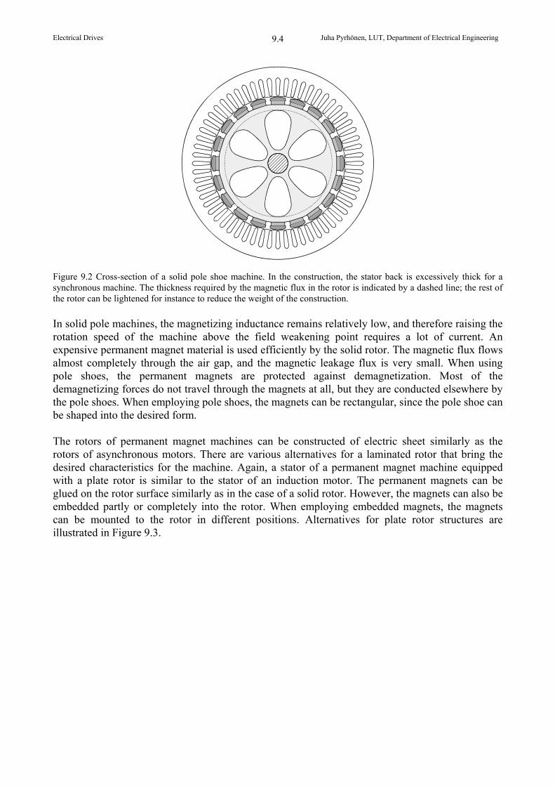
Figure 9.8 depicts the behaviour of s , when lsq = 1. and pm = 1.
Ts/TN0 1
1
1.4
s/N
Figure 9.8. Magnitude of the stator flux linkagesas a function of the torque Te, when Lsq = 1 pu and PM = 1 pu. The behaviour illustrated in Figure 9.8 can easily be detected in the vector diagram of Figure 9.9, which corresponds to the rated load of the machine.
Electrical Drives Juha Pyrhönen, LUT, Department of Electrical Engineering
9.13
d
q
PM = 1
s = 1lsqisq = 1
us = 1
s
is = isq = 1s = 45o
s = 0.707
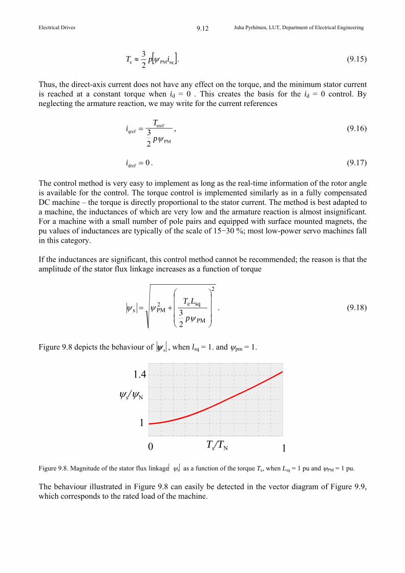
Figure 9.9 A machine implementing id = 0 control; lsq = 1 for the machine at the relative speed s = 0.707. As a result of armature reaction, the stator flux linkage obtains the value s = 1.41 at the rated current isq = 1; already at the speed s = 0.707, this value induces a back emf es = 1. The speed of the motor drive is at maximum 0.707. The power factor suffers considerably from the id = 0 control and remains at the value cos = 0.707.
As s increases, also the stator voltage increases, while the maximum speed limited by the
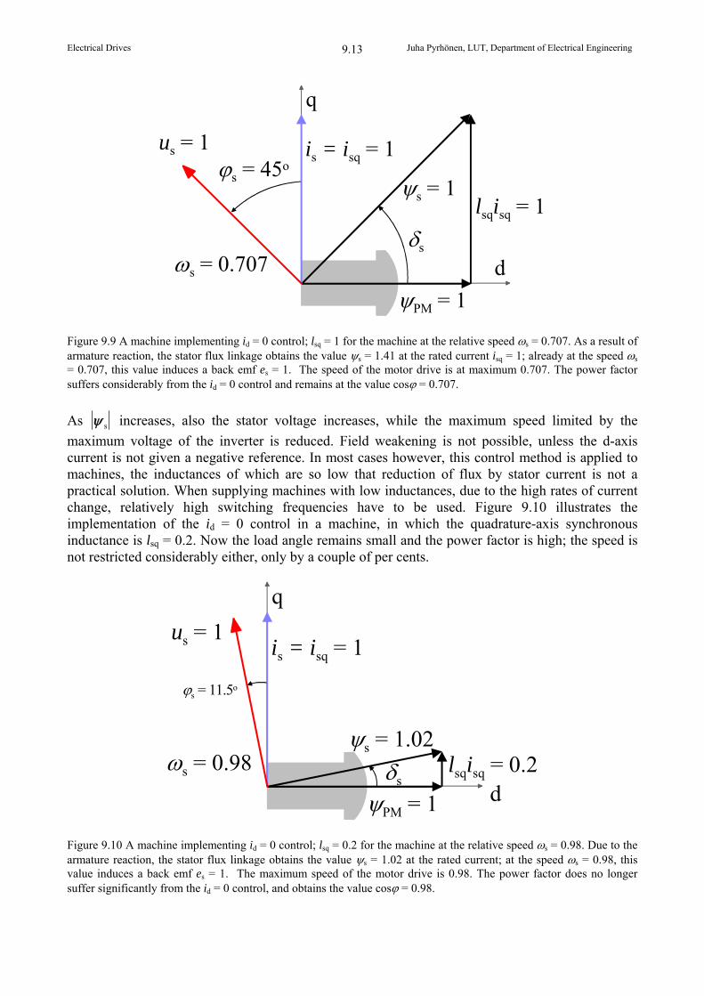
maximum voltage of the inverter is reduced. Field weakening is not possible, unless the d-axis current is not given a negative reference. In most cases however, this control method is applied to machines, the inductances of which are so low that reduction of flux by stator current is not a practical solution. When supplying machines with low inductances, due to the high rates of current change, relatively high switching frequencies have to be used. Figure 9.10 illustrates the implementation of the id = 0 control in a machine, in which the quadrature-axis synchronous inductance is lsq = 0.2. Now the load angle remains small and the power factor is high; the speed is not restricted considerably either, only by a couple of per cents.
d
q
PM = 1
s = 1.02lsqisq = 0.2
us = 1
s
is = isq = 1
s = 11.5o
s = 0.98
Figure 9.10 A machine implementing id = 0 control; lsq = 0.2 for the machine at the relative speed s = 0.98. Due to the armature reaction, the stator flux linkage obtains the value s = 1.02 at the rated current; at the speed s = 0.98, this value induces a back emf es = 1. The maximum speed of the motor drive is 0.98. The power factor does no longer suffer significantly from the id = 0 control, and obtains the value cos = 0.98.
Electrical Drives Juha Pyrhönen, LUT, Department of Electrical Engineering
9.14
Hence, id = 0 control is best adapted to machines, the armature reaction of which is small. The problem is that field weakening is not available at all, and therefore the rated speed of the motor has to be selected such that it suffices to the needs of the drive.
9.5 Method for Minimizing the Stator Current
Let us next consider the torque equation (9.14) in a steady state
T p i L L i ie PM sq mq md sd sq 3
2 . (9.19)
We can see that the reluctance torque term 3p/2(Lmd Lmq)isdisq is of significance only if the difference between the magnetizing inductances is large. Since in a PM machine, often Lmd Lmq, this term has the same sign as the term isq, when isd < 0. The current references of the dq reference frame that minimize the stator current are thus achieved when idref < 0. In the literature, two different methods are presented for the implementation of the control based on minimizing the stator current (Jahns et al. 1986; Kim and Sul 1997). First, the method introduced by Jahns et al. (1986) is discussed. First, we adopt the following normalizations
b
sddn
b
sqqn
eb
een ,,
i
ii
i
ii
T
TT , (9.20)
where
iL Lb
PM
sq sd
, (9.21)
T ieb PM b3
2 . (9.22)
The basic value for current ib can be determined only for machines with saliency, and further, it can be specified that the quadrature-axis inductance has to be higher than the direct-axis inductance. We obtain thus for the normalized torque Ten
Ten = iqn(1 idn). (9.23) We can see that in the idn iqn plane, the constant torque loci are hyperbolas, Figure 9.11
iT
iqnen
dn
1
. (9.24)
The minimum point for the stator current at a certain constant torque is obtained by finding the minimum distance of the hyperbola from the origin. The point at which this minimum value is obtained gives in turn the required references for the currents id and iq. As a solution, the current references idnref and iqnref that minimize the stator current are obtained. These references are given by the equations
Electrical Drives Juha Pyrhönen, LUT, Department of Electrical Engineering
9.15
T i ienref dnref dnref 13
, (9.25)
Ti
ienref
qnref
qnref 2
1 1 4 2 . (9.26)
2
1
0
-1
-2-1 -0.5 0 0.5
iqn
idn
Ten = 3 Ten = 2
Ten = 1
Ten = -3
Ten = -2
Ten = -1
Ten = 0
Figure 9.11 Constant torque loci for the normalized torque Ten in the id iq plane. The current references idnref and iqnref have to be computed either iteratively, or the functions idnref = f(Tenref) and iqnref = f(Tenref) have to be computed in advance. The curves for the functions are depicted in Figure 9.12.
Tenref0 1 2 3
0
-0.2
-0.4
-0.6
idn
Tenref0 1 2 3
1.6
1.2
0.8
0.4
0
iqn
(a) Direct-axis current idnref (b) Quadrature-axis current iqnref Figure 9.12 Current reference functions minimizing the stator current idnref = f (Tenref) ja iqnref = f (Tenref)
Electrical Drives Juha Pyrhönen, LUT, Department of Electrical Engineering
9.16
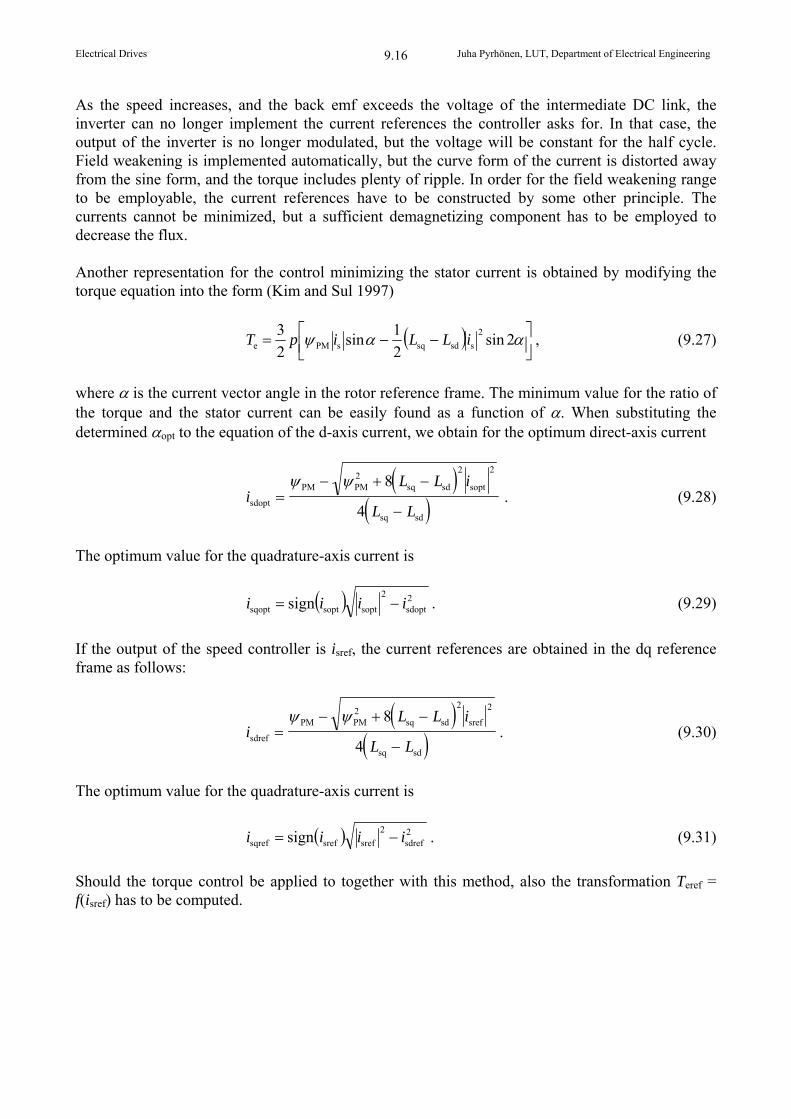
As the speed increases, and the back emf exceeds the voltage of the intermediate DC link, the inverter can no longer implement the current references the controller asks for. In that case, the output of the inverter is no longer modulated, but the voltage will be constant for the half cycle. Field weakening is implemented automatically, but the curve form of the current is distorted away from the sine form, and the torque includes plenty of ripple. In order for the field weakening range to be employable, the current references have to be constructed by some other principle. The currents cannot be minimized, but a sufficient demagnetizing component has to be employed to decrease the flux. Another representation for the control minimizing the stator current is obtained by modifying the torque equation into the form (Kim and Sul 1997)
2sin
2
1sin
2
3 2
ssdsqsPMe iLLipT , (9.27)
where is the current vector angle in the rotor reference frame. The minimum value for the ratio of the torque and the stator current can be easily found as a function of . When substituting the determined opt to the equation of the d-axis current, we obtain for the optimum direct-axis current
i
L L i
L Lsdopt
PM PM2
sq sd sopt
sq sd
8
4
2 2
. (9.28)
The optimum value for the quadrature-axis current is
2sdopt
2
soptsoptsqopt sign iiii . (9.29)
If the output of the speed controller is isref, the current references are obtained in the dq reference frame as follows:
i
L L i
L Lsdref
PM PM2
sq sd sref
sq sd
8
4
2 2
. (9.30)
The optimum value for the quadrature-axis current is
2sdref
2
srefsrefsqref sign iiii . (9.31)
Should the torque control be applied to together with this method, also the transformation Teref = f(isref) has to be computed.
Electrical Drives Juha Pyrhönen, LUT, Department of Electrical Engineering
9.17
9.6 Direct Flux Linkage and Torque Control PMSMDTC
The method proposed in the reference Takahashi and Nokuchi (1986) for the direct flux linkage and torque control was initially investigated for induction motors in particular. The principle, known as the DTC, is also applied to a commercial product (Tiitinen et al. 1995). The control method has also been applied to a sensorless closed-loop speed control of a synchronous reluctance machine Lagerquist et al. 1994) and to a PM machine (Zhong et al. 1997). The flux linkage is estimated in
the stator reference frame by the integral s,est s,est s,meas s d u i R t . This equation is the strength
of the DTC; motor parameters are not required in the calculation of the stator flux linkage, and the computation is independent of the machine type. This, however, is also a weakness of the DTC. Usually, it is not necessary to measure the stator voltage directly, but it is calculated from the DC intermediate voltage, the switch positions and the switch models. Also the accurate stator resistance estimate is essential in the estimation of the flux linkage. The resistive voltage loss occurring in the integral at low speed becomes a dominating factor when compared with the stator voltage, and thus the flux linkage estimate easily becomes erroneous, which leads to poor voltage vector choices. The stator flux linkage estimation in the motor can be improved by computing the stator flux linkage with the motor parameters (Takahashi and Nokuchi 1986; Tiitinen et al. 1995). The current model of the synchronous machine requires information of the rotor angle, and therefore the flux linkage cannot be computed without this information. A control method that is applicable to all rotation speeds of a synchronous machine is obtained by including a feedback of the rotor angle in the system, and, in addition to the voltage integral, by computing also a value for the flux linkage based on the equations sd sd sd md D PM L i L i and sq sq sq mq Q L i L i (Luukko et al. 1997).
Figure 9.13 illustrates a block diagram for the DTC control with a rotor position feedback for a permanent magnet synchronous machine. In the implementation of a DTC control system for low-inductance PM machines, a sufficient sampling frequency has to be selected for the computation of the stator flux linkage; thus, the average switching frequency can be kept adequate. On the other hand, the computation of the flux linkage with a position feedback current model is not necessary at such a high frequency. By employing the method for drift correction by Niemelä (1999) and Luukko (2000), industrial PM machines can well be run with the DTC without the rotor position information. However, the identification run of a PM machine has to start with the determination of the rotor angle. This can be done for instance by applying the method proposed in Luukko (2000) at least for all the machines that have a observable difference between the d-axis and q-axis inductances. The measurement of the rotor position is performed by using the minimum pulses of the inverter in all possible directions of the voltage vector, and by measuring the inductances by the generated current. Next, the measurement results are adjusted to form a measurement curve showing the placement of the d- and q-axes. DTC is quite well adapted for PM machines, since almost any reasonable value can be selected as the stator flux linkage reference. With the DTC, it is possible to flexibly implement all the control methods illustrated in Figs. 9.15−9.20.
Electrical Drives Juha Pyrhönen, LUT, Department of Electrical Engineering
9.18
V
Optimal switchingtable
sA, sB, sC
UDC
is
us
usA
3/2
3/2
usx usy
isx
isy
xy/dq
isd isq
PMSM T
s
s
s
corr.
sdi
sqi
dq/xy
sxu
syu
sxi
syi
sx
sy
|s|
|s|
|s| *
T
T
T*+
+
-
-
r
usCusB
Figure 9.13 Block diagram of the flux linkage and torque control of a PMSM. sxu and syu are the stator flux linkage estimates calculated as an integral of the stator voltage; these estimates are corrected from time to time by the stator flux linkage estimates sxi and syi calculated by the current model. r is the rotor angle. During the motor identification run, also the information of the flux linkage generated by the permanent magnets has to be searched. PM can be found easily on the basis of the voltage integral by rotating the motor at no load and by adjusting the flux linkage reference s,ref of the inverter in a sufficiently wide range. The flux linkage reference producing the minimum no-load current is equal to the flux linkage PM generated by the permanent magnets of the motor.
is0
s,refs = PM
is0,min
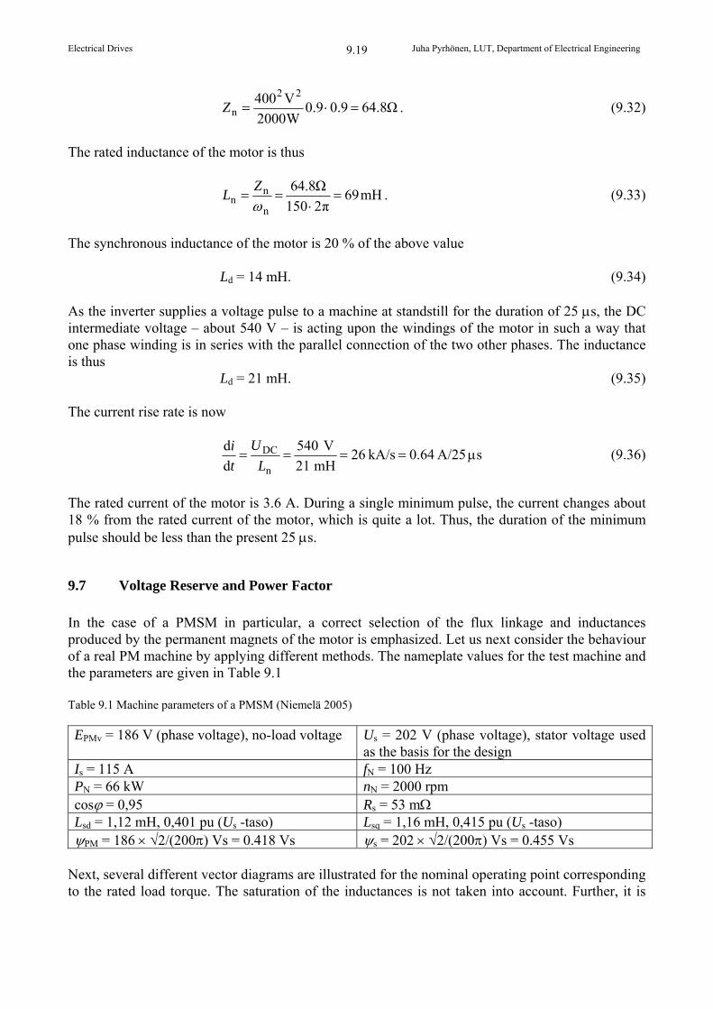
Figure 9.14 Behaviour of the no-load current is0 of a PM motor as a function of the flux linkage reference. When the current reaches its minimum value, the flux linkage PM of the permanent magnets is found. As an example of a commercial application applying the DTC, the inverter manufactured by ABB applies a minimum pulse of 25 s. This minimum pulse width is appropriate for industrial PM motors, however, it is too large for small servo motors with surface magnets. For example, let us consider a 2 kW, 400 V, 150 Hz servo motor, the relative synchronous inductance of which is ld = 0.2. If both the power factor and the efficiency of the motor are 0.9, we may solve the rated impedance for the machine
Electrical Drives Juha Pyrhönen, LUT, Department of Electrical Engineering
9.19
Ω8.649.09.0W2000
V400 22
n Z . (9.32)
The rated inductance of the motor is thus
mH69π2150
Ω8.64
n
nn
Z
L . (9.33)
The synchronous inductance of the motor is 20 % of the above value
Ld = 14 mH. (9.34) As the inverter supplies a voltage pulse to a machine at standstill for the duration of 25 s, the DC intermediate voltage – about 540 V – is acting upon the windings of the motor in such a way that one phase winding is in series with the parallel connection of the two other phases. The inductance is thus
Ld = 21 mH. (9.35) The current rise rate is now
A/25 0.64kA/s 26mH 21
V 540
d
d
n
DC L
U
t
is (9.36)
The rated current of the motor is 3.6 A. During a single minimum pulse, the current changes about 18 % from the rated current of the motor, which is quite a lot. Thus, the duration of the minimum pulse should be less than the present 25 s.
9.7 Voltage Reserve and Power Factor
In the case of a PMSM in particular, a correct selection of the flux linkage and inductances produced by the permanent magnets of the motor is emphasized. Let us next consider the behaviour of a real PM machine by applying different methods. The nameplate values for the test machine and the parameters are given in Table 9.1 Table 9.1 Machine parameters of a PMSM (Niemelä 2005)
EPMv = 186 V (phase voltage), no-load voltage Us = 202 V (phase voltage), stator voltage used as the basis for the design
Is = 115 A fN = 100 Hz PN = 66 kW nN = 2000 rpm cos = 0,95 Rs = 53 m Lsd = 1,12 mH, 0,401 pu (Us -taso) Lsq = 1,16 mH, 0,415 pu (Us -taso) PM = 186 2/(200Vs = 0.418 Vs s = 202 2/(200Vs = 0.455 Vs
Next, several different vector diagrams are illustrated for the nominal operating point corresponding to the rated load torque. The saturation of the inductances is not taken into account. Further, it is
Electrical Drives Juha Pyrhönen, LUT, Department of Electrical Engineering
9.20
pointed out that the basic value for the flux linkage is always determined according to the stator voltage in question. Figure 9.15 illustrates the operating point according to the nameplate values. Usv = 202 V
PM = 0.418 Vs
is
lsdisd
lsqisq
us
s
s
design point
s = 0.455 VsEPM = 186 V Isv = 115 A cos = 0.949 s = 24.5 Figure 9.15 Vector diagram according to the motor design point
Note the relatively low back emf of the motor. Furthermore, the designer has included a voltage reserve of 10 % in the machine. For example, a DTC inverter yields easily a 220 V phase voltage when operating on a 400 V network. Figure 9.16 illustrates the motor operation with the id = 0 control. Now, the relative inductances of the motor are rather low, which brings a fairly good result by this method. The supply voltage has been raised when compared with the previous supply, or correspondingly, the stator flux linkage reference has been raised in the DTC to the operating point of Fig. 9.15. The power factor is now smaller, and the voltage reserve is very small, which is typical of the id = 0 control. Usv = 210 V
is
lsqisq
us
s
s
id = 0
PM = 0.418 Vs
s = 0.474 VsEPM = 186 V Isv = 114 A cos = 0.918 s = 23.4 Figure 9.16 Vector diagram according to the id = 0 control at a rated torque and a rated frequency
Figure 9.17 depicts a vector diagram which yields the highest value for the power factor. The figure indicates clearly that the flux linkage produced by the permanent magnets of the motor should be higher in order to obtain an appropriate stator current at the rated torque. Now the supply voltage has been left very low, and as a result, the current increases considerably higher than intended. There is plenty of voltage reserve, and the motor drive responds well to the increases in load in dynamic states.
Electrical Drives Juha Pyrhönen, LUT, Department of Electrical Engineering
9.21
Usv = 169 V
is
lsdisd
lsqisq
us
s
q
d
best power factor PM = 0.418 Vs
s = 0.380 Vs
EPM = 186 V Isv = 130 A cos = 1 s = 30.3 Figure 9.17 Vector diagram according to the cos = 1 control at a rated torque and a rated frequency
If the flux linkage created by the permanent magnets were increased, the motor could be made to operate with a low voltage reserve and a good power factor at its nominal operating point. However, operating the motor with a small load or at no load at the rated speed would prove problematic. In this case, EPM = 225 V. At small loads, the machine should be demagnetized to ensure a sufficient voltage reserve. Figure 9.18 illustrates a machine designed by a different method at its nominal operating point. We point out that in practice, the machine requires more magnetic material or magnets with a higher coercive force. A design of this kind is particularly adapted for machines, which are not operated in the field weakening, and of which a dynamic performance is not required either. For instance, a high-power high-efficiency blower could be designed by this method. Usv = 220 V is
lsdisd
lsqisq
us
s
q
d
EPM = 225 VPM = 0.505 Vs
s = 0.494 Vs
EPM = 225 V Isv = 103 A cos = 1 s = 17.6 Figure 9.18 Vector diagram according to the cos = 1 control, when the machine is redesigned to have EPM = 225 V. The machine operates at a rated torque and at a rated frequency.
Finally, Figure 9.19 depicts the drive of the original motor, in which the stator flux linkage and the flux linkage of the permanent magnets are regulated to be of equal magnitude in the DTC supply.
Electrical Drives Juha Pyrhönen, LUT, Department of Electrical Engineering
9.22
This kind of a drive can be said to be a rather good compromise, if a good dynamics is required of the drive. Usv = 193 V
is
lsdisd
lsqisq
us
s
q
d
s
PM = 0.418 Vs
s = 0.418 Vs
EPM = 186 V Isv = 121 A cos = 0.975 s = 27.4 Figure 9.19 Control method, in which s,ref = PM at a rated torque and at a rated frequency.
In the latter case, there is quite a lot of voltage reserve left, the power factor is rather good, and the motor current is only slightly higher than intended. Field weakening of the motor Let us next consider a motor drive with respect to the field weakening. There is a 400 V inverter in the drive, for which INinv = 147 A and the maximum output phase voltage is 230 V. Further, UDCmax = 730 V is defined for the sake of the DC link protection. The upper limit for the field weakening range can be roughly determined for our example machine according to the maximum DC intermediate voltage
Hz160Hz10023186
730limitfwp,
f . (9.37)
Now the no-load voltage of a PM machine is approximately EPMv = 298 V, which suffices to produce a 730 V voltage in the intermediate DC link, if the d-axis demagnetizing current produced by the control disappears for some reason. On the other hand, if we rely on the inverter’s ability to operate in the field weakening, the motor can be run even faster than this. If the rated current of the motor is used to demagnetize the motor, its flux can be reduced by id ld = 1 0.401 = 0.401 in per unit value. Thus, in pu value, there remains 60 % of the flux, and therefore, the frequency can be raised in the ratio of 1/0.6, that is, to be 1.67 times the rated frequency. Since EPM at the rated frequency (100 Hz) is only 186 V, even a higher frequency can be reached by raising the voltage from the no-load voltage of 186 V to 230 V, in which case the frequency is 230/186 167 Hz = 206 Hz. If the current reserve of the inverter is consumed completely in the demagnetizing of the motor at a full 230 V phase voltage, the maximum frequency of the motor in the field weakening becomes 206
Electrical Drives Juha Pyrhönen, LUT, Department of Electrical Engineering
9.23
Hz INinv/INmotor = 206 Hz 147 A/115 A = 264 Hz. Now, the stator flux linkage would be 0.196 Vs (43 % of the stator flux linkage at the nominal operating point). Should the demagnetizing current of the inverter disappear for some reason at this operating point, the stator flux linkage will increase to the value 0.418 Vs determined by the permanent magnets, and correspondingly, the terminal phase voltage of the motor will rise to the value of 264 V 2 0.418/2 = 490 V. The line-to-line voltage is 849 V and the peak voltage of the intermediate DC link is 1200 V, which would inevitably destroy the capacitors. A 230 V stator phase current can be produced by the inverter, and thus the actual field weakening point for an example machine running at no load is
Hz123Hz100186
230fwp f . (9.38)
In the field weakening range, some of the stator current, and in some cases, finally all the stator current is consumed in reducing the stator flux linkage. Consequently, more stator current is required in the field weakening range than for the corresponding torque in the constant flux range. Figure 9.20 shows the behaviour of different voltages at different supply frequency ranges of this motor. When investigating Figure 9.20, we can see that the field weakening of a PM machine is quite a complex issue. The major problem in PM machines is the fixed flux linkage PM, which in the field weakening soon creates a risk to the voltage withstanding of the inverter. In our example case, the speed can be raised from the rated value of 100 Hz to 160 Hz without a risk of damaging the inverter. This is based on the rather low no-load voltage of the machine. If the no-load voltage is determined close to the maximum voltage given by the inverter or even above it, the failure risk may be realized already close to the nominal operating point. Finally, Figure 9.21 shows a vector diagram of operation at a safe upper limit (160 Hz) of the field weakening range, when the inverter operates at its own rated current and the stator current corresponds to a stator voltage of 230 V, in which case the stator flux linkage is s = 0.323 Vs.
Electrical Drives Juha Pyrhönen, LUT, Department of Electrical Engineering
9.24
Figure 9.20 Behaviour of the motor voltage and the back emf at different points. 160 Hz corresponds to the induced voltage generated by the motor EPM = 298 V, which is the maximum voltage that the DC link capacitor can withstand without failure in a case in which the motor control ceases to operate at a speed of 160 Hz. This is where safe field weakening range ends. By using the rated current of the motor in the demagnetizing of the machine, a frequency of 206 Hz can be reached in the no-load operation. By using the rated current of the inverter completely in the demagnetizing of the machine, the no-load operating point can be shifted up to the frequency of 264 Hz. Now the back emf is EPM = 490 V, the stator voltage is 230 V, and the stator flux linkage is 0.196 Vs.
s = 0.455 Vs
f/Hz
constant flux range
us
Us
Us/V
0 120 160 206 264
298
230
0
Us =202 V
100 Hz
voltage reserve
EPM
186 V
490 V
field weakening range
s = 0.196 Vs
PM = 0.418 Vs
is
lsdisd
lsqisq
us
s
q
d
s
-ePM
s = 0.323 Vs
Figure 9.21 The nominal operating point of the motor at the rated current of the inverter at a 1.6-fold rated speed. Us = 230 V, EPM = 298 V, Is = 147 A, cos = 0.987, s = 34, P = 97 kW, f = 160 Hz, T = 0.915 TN. The motor runs thus almost at its rated torque even at a 60 % overspeed, and thereby yields an extremely high power when compared with its rated power. This is possible due to the high rated current of the inverter and the low rated back emf of the motor.
Electrical Drives Juha Pyrhönen, LUT, Department of Electrical Engineering
9.25
9.8 On Speed and Position Sensorless Control Methods for PM Machines
Speed and position sensorless control methods are also currently a subject of intensive research. Several control methods have been introduced based either on the calculation of the flux linkage (measurement of currents and voltages) (Wu and Slemon 1990; Ertugrul and Acarnley 1994; Östlund and Brokemper 1996; Kim and Sul 1997), on state estimators (Consoli et al. 1994; Moynihan et al. 1994), on Kalman filters (Schroedl 1990; Dhaouadi et al. 1991), or on the inductance variation information (Kulkarni and Ehsani 1992) Rotor angle estimate is usually used in connection with some current vector control method. DTC is among the most promising methods for the position sensorless control; furthermore, it is independent of the type of the rotating-field machine. Niemelä (1999) and Luukko (2000) have developed methods for the implementation of a position sensorless DTC drive. Several of the proposed algorithms apply different methods close to the zero speed and at a high speed (Schroedl 1990). In the position sensorless control of a PM machine, the initial rotor angle has always to be determined. A method for this purpose has been developed for instance by Luukko (2000). Several methods employ scalar control to accelerate the rotor to a speed, in which the state estimator detects the rotor angle. So far, there is no general method for the determination of the initial angle that would encompass all PM machine types. Methods based on the detection and identification of the difference between the d-axis and q-axis inductance components are introduced for instance in Schroedl (1990) and Östlund and Brokemper (1996). The methods based on inductance differences may be employable also in non-salient pole machines, in which the saturation caused by permanent magnets can be detected as an inductance difference. In that case, the lowest inductance is detected in the direction of the positive d-axis, and the highest in the direction of the negative d-axis; the excitation curve of Figure 9.22 illustrates the case.
sÄU
dÄi
sÄU
dÄimagnetizing in the opposite direction than the permanent magnets
magnetizing in the samedirection as the permanentmagnets
Figure 9.22 No-load curve of a PM machine and the detection of inductance changes. When the machine is magnetized in no-load operation in the same direction as the permanent magnets, an equal voltage change produces a larger change in the no-load current than when demagnetizing the machine. Next, we discuss as an example the method originally introduced by Acarnley (1994) and presented in somewhat simplified form by Östlund and Brokemper (1996). An estimate is computed for the
Electrical Drives Juha Pyrhönen, LUT, Department of Electrical Engineering
9.26
stator flux linkage, similarly as in the direct flux linkage and torque control, by employing the
equation s,est s,est s,meas s d u i R t . When T is the integration time, we obtain the discrete flux
linkage, decomposed into xy components
sx sx s sx sxk T u k R i k k 1 , (9.39)
sy sy s sy syk T u k R i k k 1 . (9.40)
The integration is improved by comparing the stator current estimates sysxˆ and ˆ ii with the
measured currents sysx and ii
sxsxsxˆΔ i-ii , (9.41)
sysysyˆΔ i-ii . (9.42)
Stator flux linkage is determined with the rotor angle r by equations
rPMsxssx cos iL , (9.43)
rPMsyssy sin iL . (9.44)
This division into components is illustrated in Figure 9.23.
x
y
d
q
r
PM
s
lsisx
s
PMcosr
PMsinr
isisy
isx
lsisy
Figure 9.23 The components of Eqs. (9.43 and 9.44)
Stator current estimates can now be computed with the rotor angle estimate kr as follows
kL
i rPMsxs
sxˆcosˆ
1ˆ , (9.45)
kL
i rPMsys
syˆsinˆ
1ˆ . (9.46)
Electrical Drives Juha Pyrhönen, LUT, Department of Electrical Engineering
9.27
We assume that the direct and quadrature inductances are equal Ld = Lq = Ls. If we assume further that we have a constant inductance, the flux linkage is a function of current and rotor angle. Hence we may write a total differential for the flux linkage
rrΔΔΔ
i
i. (9.47)
The rotor angle estimate r is corrected by such rΔ that the flux linkage error becomes zero.
Now, the correction rΔ can be calculated by the equation
rr /ΔˆΔ
ii . (9.48)
The corrected rotor angle estimate kcr is now
rrcr
ˆΔˆˆ k (9.49)
We calculate the partial derivatives and obtain the correction terms in xy components
rPM
ssxxr ˆsin
ΔˆΔ
Li , (9.50)
rPM
ssyyr ˆcos
ΔˆΔ
L
i . (9.51)
A drawback of these equations are the zeros of the denominator; the problem can be solved by observing the error and correction terms in an estimated rotor reference frame. The correction term of the rotor angle estimate becomes thus
PM
ssqr ΔˆΔ
Li . (9.52)
Finally, new values are computed for the flux linkage with the updated rotor angle estimate
kiL crPMsxssxˆcos , (9.53)
kiL crPMsyssyˆsin . (9.54)
According to Östlund and Brokemper (1996), the algorithm functions well both dynamically and in a steady state from approximately 3 Hz up to rated speed. However, like several other estimation algorithms, also this method is parameter sensitive; the effect of stator resistance estimate in particular is significant. Also the saturation of inductances has to be taken into account. A drawback of the method is the assumption that the direct and quadrature inductances are equal.
Electrical Drives Juha Pyrhönen, LUT, Department of Electrical Engineering
9.28
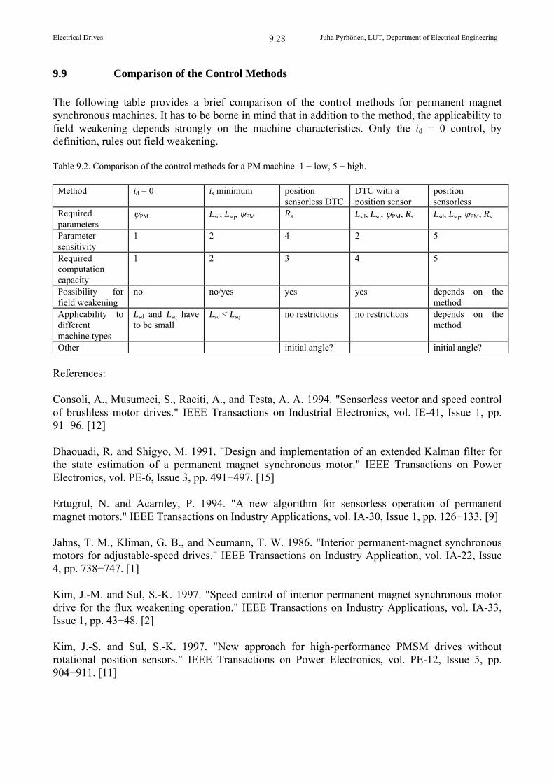
9.9 Comparison of the Control Methods
The following table provides a brief comparison of the control methods for permanent magnet synchronous machines. It has to be borne in mind that in addition to the method, the applicability to field weakening depends strongly on the machine characteristics. Only the id = 0 control, by definition, rules out field weakening. Table 9.2. Comparison of the control methods for a PM machine. 1 − low, 5 − high.
Method id = 0 is minimum position sensorless DTC
DTC with a position sensor
position sensorless
Required parameters
PM Lsd, Lsq,PM Rs Lsd, Lsq,PM, Rs Lsd, Lsq,PM, Rs
Parameter sensitivity
1 2 4 2 5
Required computation capacity
1 2 3 4 5
Possibility for field weakening
no no/yes yes yes depends on the method
Applicability to different machine types
Lsd and Lsq have to be small
Lsd < Lsq no restrictions no restrictions depends on the method
Other initial angle? initial angle?
References: Consoli, A., Musumeci, S., Raciti, A., and Testa, A. A. 1994. "Sensorless vector and speed control of brushless motor drives." IEEE Transactions on Industrial Electronics, vol. IE-41, Issue 1, pp. 91−96. [12] Dhaouadi, R. and Shigyo, M. 1991. "Design and implementation of an extended Kalman filter for the state estimation of a permanent magnet synchronous motor." IEEE Transactions on Power Electronics, vol. PE-6, Issue 3, pp. 491−497. [15] Ertugrul, N. and Acarnley, P. 1994. "A new algorithm for sensorless operation of permanent magnet motors." IEEE Transactions on Industry Applications, vol. IA-30, Issue 1, pp. 126−133. [9] Jahns, T. M., Kliman, G. B., and Neumann, T. W. 1986. "Interior permanent-magnet synchronous motors for adjustable-speed drives." IEEE Transactions on Industry Application, vol. IA-22, Issue 4, pp. 738−747. [1] Kim, J.-M. and Sul, S.-K. 1997. "Speed control of interior permanent magnet synchronous motor drive for the flux weakening operation." IEEE Transactions on Industry Applications, vol. IA-33, Issue 1, pp. 43−48. [2] Kim, J.-S. and Sul, S.-K. 1997. "New approach for high-performance PMSM drives without rotational position sensors." IEEE Transactions on Power Electronics, vol. PE-12, Issue 5, pp. 904−911. [11]
Electrical Drives Juha Pyrhönen, LUT, Department of Electrical Engineering
9.29
Kulkarni, A. B. and Ehsani, M. 1992. "A novel position sensor elimination technique for the interior permanent-magnet synchronous motor drive." IEEE Transactions on Industry Applications, vol. IA-28, Issue 1, pp. 144−150. [16] Lagerquist, R., Boldea, I., and Miller, T. J. E. 1994. "Sensorless control of the synchronous reluctance motor." IEEE Transactions on Industry Applications, vol. IA-30, pp. 673−682. [5] Luukko, J. 2000. Direct torque control of permanent magnet synchronous machines – analysis and implementation. Acta Universitatis Lappeenrantaensis. Dissertation, Lappeenranta University of Technology. [18] Luukko, J., Kaukonen, J., Niemelä, M., Pyrhönen, O., Pyrhönen, J., Tiitinen, P., Väänänen, J. 1997. "Permanent magnet synchronous motor drive based on direct flux linkage control." in Proceedings of the 7th European Conference on Power Electronics and Applications, vol. 3, pp. 683−688. [7] Moynihan, J. F., Egan, M. G., and Murphy, J. M. D. 1994. "The application of state observers in current regulated PM synchronous drives." in IEEE IECON, pp. 20−25. [13] Niemelä, M. 1999. Position sensorless electrically excited synchronous motor drive for industrial use, based on direct flux linkage and torque control. Acta Universitatis Lappeenrantaensis. Dissertation, Lappeenranta University of Technology. [17]