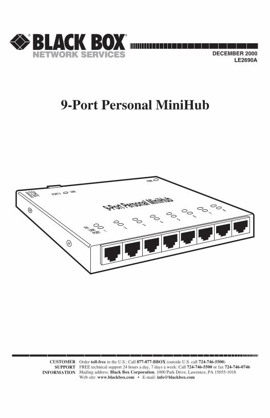
CUSTOMER SUPPORT INFORMATION Order toll-free in the U.S.: Call 877-877-BBOX (outside U.S. call 724-746-5500) FREE technical support 24 hours a day, 7 days a week: Call 724-746-5500 or fax 724-746-0746 Mailing address: Black Box Corporation, 1000 Park Drive, Lawrence, PA 15055-1018 Web site: www.blackbox.com • E-mail: [email protected]9-Port Personal MiniHub RX LINK PORT 9-Port Personal MiniHub 1 2 3 4 PORT 9 PWR LINK UP LINK 5 6 7 8 DECEMBER 2000 LE2690A
Transcript
CUSTOMERSUPPORT
INFORMATION
Order toll-free in the U.S.: Call 877-877-BBOX (outside U.S. call 724-746-5500)FREE technical support 24 hours a day, 7 days a week: Call 724-746-5500 or fax 724-746-0746Mailing address: Black Box Corporation, 1000 Park Drive, Lawrence, PA 15055-1018Web site: www.blackbox.com • E-mail: [email protected]
9-Port Personal MiniHub
RXLINK
PORT
9-Port Personal MiniHub
12 3
4
PORT 9
PWR
LINKUP LINK
56
78
DECEMBER 2000LE2690A
FEDERAL COMMUNICATIONS COMMISSIONand CANADIAN DEPARTMENT OF COMMUNICATIONS
RADIO FREQUENCY INTERFERENCE STATEMENT
Class B Digital Device. This equipment has been tested and found to comply withthe limits for a Class B computing device pursuant to Part 15 of the FCC Rules.These limits are designed to provide reasonable protection against harmfulinterference in a residential installation. However, there is no guarantee thatinterference will not occur in a particular installation. This equipment generates,uses, and can radiate radio frequency energy, and, if not installed and used inaccordance with the instructions, may cause harmful interference to radiocommunications. If this equipment does cause harmful interference to radio ortelephone reception, which can be determined by turning the equipment off andon, the user is encouraged to try to correct the interference by one of the followingmeasures:
• Reorient or relocate the receiving antenna.
• Increase the separation between the equipment and receiver.
• Connect the equipment into an outlet on a circuit different from that to whichthe receiver is connected.
• Consult an experienced radio/TV technician for help.
Caution:Changes or modi f ica t ions not express ly approved by the par tyresponsible for compliance could void the user’s authority to operate theequipment.
To meet FCC requirements, shielded cables and power cords are required toconnect this device to a personal computer or other Class B certified device.
This digital apparatus does not exceed the Class B limits for radio noise emission from digitalapparatus set out in the Radio Interference Regulation of the Canadian Department ofCommunications.
Le présent appareil numérique n’émet pas de bruits radioélectriques dépassant les limitesapplicables aux appareils numériques de classe B prescrites dans le Règlement sur le brouillageradioélectrique publié par le ministère des Communications du Canada.
1. Todas las instrucciones de seguridad y operación deberán ser leídasantes de que el aparato eléctrico sea operado.
2. Las instrucciones de seguridad y operación deberán ser guardadaspara referencia futura.
3. Todas las advertencias en el aparato eléctrico y en sus instrucciones deoperación deben ser respetadas.
4. Todas las instrucciones de operación y uso deben ser seguidas.
5. El aparato eléctrico no deberá ser usado cerca del agua—por ejemplo,cerca de la tina de baño, lavabo, sótano mojado o cerca de una alberca,etc..
6. El aparato eléctrico debe ser usado únicamente con carritos opedestales que sean recomendados por el fabricante.
7. El parato eléctrico debe ser montado a la pared o al techo sólo comosea recomendado por el fabricante.
8. Servicio—El usuario no debe intentar dar servicio al equipo eléctricomás allá a lo descrito en las instrucciones de operación. Todo otroservicio deberá ser referido a personal de servicio calificado.
9. El aparato eléctrico debe ser situado de tal manera que su posición nointerfiera su uso. La colocación del aparato eléctrico sobre una cama,sofá, alfombra o superficie similar puede bloquea la ventilación, no sedebe colocar en libreros o gabinetes que impidan el flujo de aire por losorificios de ventilación.
10. El equipo eléctrico deber ser situado fuera del alcance de fuentes decalor como radiadores, registros de calor, estufas u otros aparatos(incluyendo amplificadores) que producen calor.
11. El aparato eléctrico deberá ser connectado a una fuente de poder sólodel tipo descrito en el instructivo de operación, o como se indique en elaparato.
NOM STATEMENT, TRADEMARKS
12. Precaución debe ser tomada de tal manera que la tierra fisica y lapolarización del equipo no sea eliminada.
13. Los cables de la fuente de poder deben ser guiados de tal manera queno sean pisados ni pellizcados por objetos colocados sobre o contraellos, poniendo particular atención a los contactos y receptáculos dondesalen del aparato.
14. El equio eléctrico debe ser limpiado únicamente de acuerdo a lasrecomendaciones del fabricante.
15. En caso de existir, una antena externa deberá ser localizada lejos de laslineas de energia.
16. El cable de corriente deberá ser desconectado del cuando el equipo nosea usado por un largo periodo de tiempo.
17. Cuidado debe ser tomado de tal manera que objectos liquidos no seanderramados sobre la cubierta u orificios de ventilación.
18. Servicio por personal calificado deberá ser provisto cuando:
A: El cable de poder o el contacto ha sido dañado; u
B: Objectos han caído o líquido ha sido derramado dentro delaparato; o
C: El aparato ha sido expuesto a la lluvia; o
D: El aparato parece no operar normalmente o muestra un cambio ensu desempeño; o
E: El aparato ha sido tirado o su cubierta ha sido dañada.
2. Introduction ......................................................................................... 32.1 General Overview .......................................................................... 32.2 Features and Benefits .................................................................... 42.3 Applications ................................................................................... 5
3. Installation ............................................................................................ 73.1 Before You Install: The Complete Package .................................. 73.2 The Installation Procedure ........................................................... 73.3 Cascading ..................................................................................... 10
4. Operation ........................................................................................... 114.1 LED Indicators ............................................................................ 114.2 Operating Features ...................................................................... 11
5. Troubleshooting ................................................................................. 135.1 Things to Check ........................................................................... 135.2 Calling Your Supplier ................................................................. 145.3 Shipping and Packaging .............................................................. 14
1
CHAPTER 1: Specifications
Compliance — FCC Part 15 Class A and B, DOC Class/MDC classe B,VDE Class B
Standard — IEEE 802.3 Ethernet v. 1.0/2.0
Interface — 10BASE-T
Data Rate — 10 Mbps
Partitioning — Automatic after 32 consecutive collisions
Reconnection — Occurs after 512 bits of error-free transmission
Maximum Segment Length — UTP (unshielded 10BASE-T): 100 m (328 ft.);
STP (shielded 10BASE-T): 150 m (492 ft.)
User Controls — Rear-mounted slide switch for straight-through vs.crossover (uplink) operation
Indicators — (18) Top-mounted recessed LEDs:(1) Power; (9) Link (1 for each port); (8) RX (1 foreach front-panel port)
On front ports and (when set for straight-throughoperation) the rear port: Receive +, Receive –,Transmit +, and Transmit – respectively;
On rear port (set for crossed operation): Transmit +,Transmit –, Receive +, and Receive – respectively
1. Specifications
2
9-PORT PERSONAL MINIHUB
Power — From wallmount power supply:Input: 120 VAC, 60 Hz;Output: 12 VDC, 1 amp;Consumption: 10 watts maximum
Enclosure — High-strength steel
Cooling Method — Convection
OperatingTemperature — 32 to 122˚ F (0 to 50˚ C)
StorageTemperature — –4 to 140˚ F (–20 to 60˚ C)
Humidity — 10 to 95% noncondensing
Size — 0.8"H x 5"W x 4.4"D (1.9 x 12.7 x 11.2 cm)
Weight — Net: 1 lb. (0.5 kg);Net plus power supply: 2 lb. (0.9 kg)
3
CHAPTER 2: Introduction
2.1 General OverviewThe 9-Port Personal MiniHub is a workplace hub in a very compactpackage. It is simple to install and use in an office or lab environment,requiring no special rack cabinets or wiring-closet apparatus. It is astandard physical-layer Ethernet product and operates independently of allsoftware.Personal MiniHubs provide a simple and inexpensive solution for
networking a personal multi-system office using 10BASE-T twisted-paircabling. They can expand an existing single-network-port outlet to provideup to eight extra ports in the immediate office or lab area.Personal MiniHubs are also well suited for small-to-medium-size office or
lab environments (two to eight users) that need an independent Ethernetnetwork. They operate as self-sufficient units to provide 10BASE-TEthernet connectivity for local users and devices. Small independentnetworks built using the 9-Port Personal MiniHubs are easily expanded bytaking advantage of the MiniHubs’ uplink-switchable port to add hubs ofequal or greater capacity in a cascade (see Section 3.3).The small size of the Personal MiniHubs make them very useful for
demonstration situations in conference rooms and in exhibitions where atemporary or expansion network is needed. The MiniHubs are also handyas a piece of test equipment that can be easily inserted into the network toprovide a test port, and then removed after the testing is done. They takeup minimal space and use minimal power, and are rugged enough to becarried in a coat pocket for possible emergencies.Personal MiniHubs fit easily into the workplace environment. They can
be table-top- or shelf-mounted, or you can use the included Velcro® strip tomount MiniHubs on walls or on the back or side of a desk or cabinet. All ofthe wiring connectors are in the same plane so that wiring space is neat andminimal. The external power supply conveniently plugs into an availableAC wall receptacle or power strip.The 9-Port Personal MiniHub’s RJ-45 ports support connection of up to
nine workstations or other network devices over full-length 10BASE-T cablesegments. Personal MiniHubs fully comply with the IEEE 802.3
2. Introduction
4
9-PORT PERSONAL MINIHUB
specification for repeater functionality: They perform signal amplification,retiming of data packets, and regeneration of preamble bits for each packetreceived. They will also detect collisions, extend collision fragments, andautomatially partition and reconnect individual ports in order to keepproblems on one segment from causing downtime elsewhere on thenetwork.Personal MiniHubs have LINK and RX LEDs for each front-panel RJ-45
port, located above the corresponding ports (see the illustration below), oneLINK LED for (and located above) the rear-panel port, and one LED forAC power located at the rear above the external power-supply connection.This makes observing the operation and status of the ports easy.
The included extemal wallmount power supply uses AC input power of120 VAC/60 Hz. Its lightweight cord carries DC power to the barrel-typepower jack on the rear panel (shown below) of the MiniHub.
2.2 Features and Benefits• Interconnectability with Existing Ethernet NetworksYour 9-Port Personal MiniHub has a manual Up-Link switch that youcan use to cross the pinning of its rear port. In this setting, you canconnect 10BASE-T cable from an existing Ethernet environment (suchas the central hub for the building) to the MiniHub’s rear port.
• Interoperability with Other Ethernet DevicesPersonal MiniHubs are completely interoperable with other Ethernet-compliant network devices. Each is fully compliant with IEEE 802.3specifications for 10 Mbps CSMA/CD operation. This allows PersonalMiniHubs to be integrated into any standard Ethernet network.
Front-panelports
PowerJack
Rear-PanelPort
Up-LinkSwitch
LEDs
5
CHAPTER 2: Introduction
• Installation VersatilityYou can easily install Personal MiniHubs in almost any office or lablocation. The tiny package is very unobtrusive and is typically mountedwith Velcro.
• Robust Netork OperationPersonal MiniHubs use the “star” network topology and have automaticper-port partitioning and reconnection. A fault on one segment isisolated from the rest of the network, avoiding most network downtime.
• Simple Network Diagnosis and Maintenance with LEDsPersonal MiniHubs are equipped with a full complement of LEDs toshow the status of basic network activity. LINK LEDs for each port offera very simple way to verify operational connections for each 10BASE-Tsegment.
• Low-cost Standalone 10BASE-T ConnectivityOperating your Personal MiniHub in a standalone environment as aself-sufficient device is a very low-cost method of providing smallworkgroups access to a variety of Ethernet networking services such asfile sharing, email, printer sharing, and other computer information.
• High-Quality ConstructionPersonal MiniHubs have rugged steel enclosures and are compliantwith rigid Class B emission standards, making them suitable forcommercial and home offices.
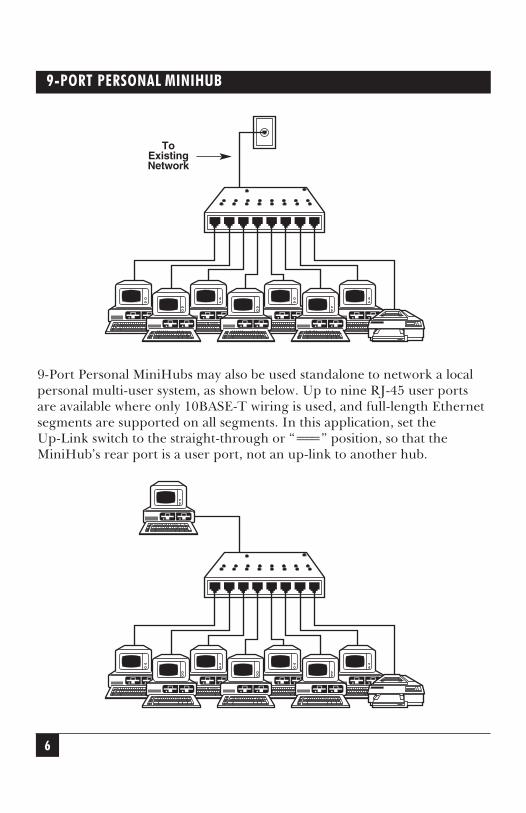
2.3 ApplicationsExpanding from one to multiple ports at an existing site is easy, andrequires no modification to typical building wiring. Simply plug the existingnetworked device’s network-cable segment into one of the 9-Port PersonalMiniHub’s front-mounted RJ-45ports. With the MiniHub’s rear-mountedUp-Link switch set to “=x=”, run 10BASE-T cable from the existingnetwork outlet to the MiniHub’s rear port. Then plug the DC power cordof the MiniHub’s external power supply into the MiniHub’s power jack,plug in the power supply’s transformer, and there you are: In minutes, youhave added eight new ports for other networked devices (see the illustrationat the top of the next page).
6
9-PORT PERSONAL MINIHUB
9-Port Personal MiniHubs may also be used standalone to network a localpersonal multi-user system, as shown below. Up to nine RJ-45 user portsare available where only 10BASE-T wiring is used, and full-length Ethernetsegments are supported on all segments. In this application, set theUp-Link switch to the straight-through or “===” position, so that theMiniHub’s rear port is a user port, not an up-link to another hub.
ToExistingNetwork
7
CHAPTER 3: Installation
3.1 Before You Install: Inspecting the Complete PackageExamine the shipping container for obvious damage prior to installing thisproduct; notify the carrier of any damage which you believe occurredduring shipment ar delivery. Inspect the contents of this package for anysigns of damage and make sure that you received these items:
• (1) 9-Port Personal MiniHub
• (1) External 120-VAC 60-Hz power supply
• (1) Velcro tape section, approximately 3 inches (7.6 cm) in length
• (2) Brackets for optional screw-mounting
• (1) Copy of this manual
Remove the 9-Port Personal MiniHub from the shipping container. Keepthe container in case you need to ship the unit later.If any items are missing or damaged, contact your supplier. If you need
to return the unit, see Sections 5.2 and 5.3.
3.2 The Installation ProcedureInstalling a 9-Port Personal MiniHub is very simple. First, keeping in mindthat it must be within 6 feet (1.8 m) of an AC outlet, decide how and whereyou’re going to mount the MiniHub.
3.2.1 MOUNTING THE MINIHUB
Tabletop- or Shelf-Mounting9-Port Personal MiniHubs are easily mounted on a tabletop or shelf, andhave four rubber feet to provide stability without scratching finishedsurfaces. A piece of Velcro may be used to add additional stability if desired.When properly installed, the top-mounted LED status indicators will be inplain view and easy to read.The rugged steel case of the Personal Hub will protect it from accidental
damage in an office or lab workplace. Keep an open area around the unitso that convection cooling can occur while the unit is operating.
3. Installation
8
9-PORT PERSONAL MINIHUB
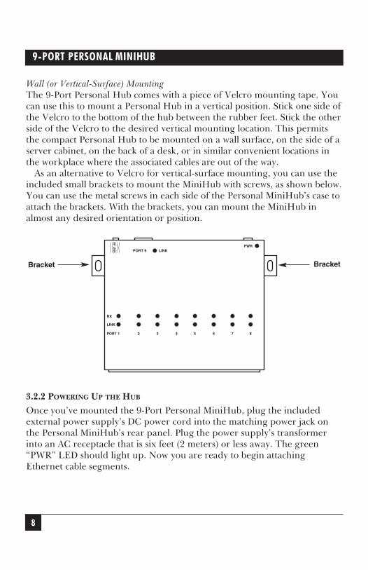
Wall (or Vertical-Surface) MountingThe 9-Port Personal Hub comes with a piece of Velcro mounting tape. Youcan use this to mount a Personal Hub in a vertical position. Stick one side ofthe Velcro to the bottom of the hub between the rubber feet. Stick the otherside of the Velcro to the desired vertical mounting location. This permitsthe compact Personal Hub to be mounted on a wall surface, on the side of aserver cabinet, on the back of a desk, or in similar convenient locations inthe workplace where the associated cables are out of the way.As an alternative to Velcro for vertical-surface mounting, you can use the
included small brackets to mount the MiniHub with screws, as shown below.You can use the metal screws in each side of the Personal MiniHub’s case toattach the brackets. With the brackets, you can mount the MiniHub inalmost any desired orientation or position.
3.2.2 POWERING UP THE HUB
Once you’ve mounted the 9-Port Personal MiniHub, plug the includedexternal power supply’s DC power cord into the matching power jack onthe Personal MiniHub’s rear panel. Plug the power supply’s transformerinto an AC receptacle that is six feet (2 meters) or less away. The green“PWR” LED should light up. Now you are ready to begin attachingEthernet cable segments.
UP
LIN
K
PORT
LINK
RX
1 2 3 4 5 6 7 8
PORT 9 LINKPWR
Bracket Bracket
9
CHAPTER 3: Installation
3.2.3 CONNECTING TWISTED-PAIR SEGMENTS TO THE FRONT-PANEL PORTS
1. Insert the male plug on one end of a standard 10BASE-T cable intoone of the RJ-45 female ports on the front panel of the 9-Port PersonalMiniHub. (Even though the MiniHub’s connectors are shielded, theywill accept, and operate properly with, either unshielded- or shielded-type RJ-45 twisted-pair wiring plugs.)
2. Connect the other end of each network segment to a workstation oruser device. If the MiniHub is getting AC power, it will light the“LINK” LED corresponding to each MiniHub port that has apowered-up and functional device attached to it.
3.2.4 USING THE REAR-PANEL PORT AND THE UP-LINK SWITCH
For the rear-panel RJ-45 port only, use the Up-Link crossover switch (alsoon the rear panel) to select either a normal 10BASE-T connection to a userdevice (switch in the “===” position) or a special network-uplink connectionto another hub or concentrator (switch in the “=x=” position). A specialcross-pinned cable for uplinks is not needed with Personal MiniHubs,because with the Up-Link switch in the “=x=” position the pinning iscrossed inside the MiniHub.Insert the male plug on one end of a standard 10BASE-T cable into the
RJ-45 female port on the rear panel of the 9-Port Personal MiniHub.Connect the other end of the network segment to a workstation or userdevice if the Up-Link switch is in the “===” position, or to a network hubor concentrator if the Up-Link switch is in the “=x=” position.Even when the rear port is physically uplinked (cable runs from the port
to a larger network), you can logically isolate the users and devices on the9-Port Personal MiniHub by moving the Up-Link switch to the “===”position. In this situation, the uplink segment is inoperative and fullbandwidth is available locally.
10
9-PORT PERSONAL MINIHUB
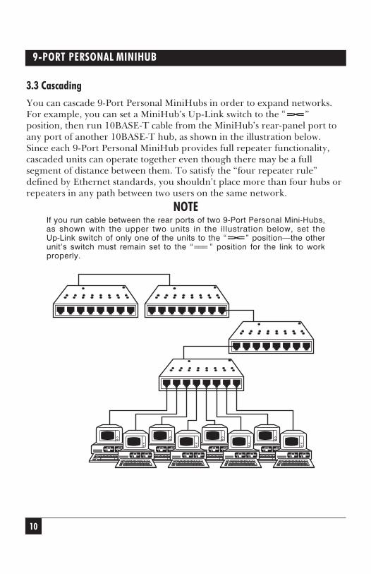
3.3 CascadingYou can cascade 9-Port Personal MiniHubs in order to expand networks.For example, you can set a MiniHub’s Up-Link switch to the “=x=”position, then run 10BASE-T cable from the MiniHub’s rear-panel port toany port of another 10BASE-T hub, as shown in the illustration below.Since each 9-Port Personal MiniHub provides full repeater functionality,cascaded units can operate together even though there may be a fullsegment of distance between them. To satisfy the “four repeater rule”defined by Ethernet standards, you shouldn’t place more than four hubs orrepeaters in any path between two users on the same network.
NOTEIf you run cable between the rear ports of two 9-Port Personal Mini-Hubs,as shown with the upper two units in the illustration below, set theUp-Link switch of only one of the units to the “=x=” position—the otherunit’s switch must remain set to the “===” position for the link to workproperly.
11
CHAPTER 4: Operation
This chapter describes the LEDs and operating features of the 9-PortPersonal MiniHubs. The 9-Port Personal MiniHubs are fully compliant withthe Ethemet Version 2/IEEE 802.3 Repeater Specification for CSMA/CD10-Mbps operation and will function accordingly.
4.1 LED IndicatorsPower On (PWR) LED: Shines GREEN to show functional DC power.
Link Status (LINK) LEDs: 9-Port Personal MiniHubs have a LINK LED foreach port, which shines GREEN when the MiniHub detects that a10BASE-T segment is properly connected to that port. Each LINK LED willturn OFF independently if either end of the segment’s cable comes loose orif the MiniHub or the device at the other end loses power.
NOTEWhen the rear port is physically uplinked (cabled) to another hub, theLINK LED will normally be ON when the Up-Link switch is set to the“=x=” position. If you isolate the MiniHub for full-bandwidth localoperation by moving the Up-Link switch to the “===” position, the LINKLED will be OFF because the up-link is logically disabled.
Receive Packets (RX) LEDs: The RX LEDs, one for each RJ-45 port, flickerGREEN to show that data packets are being received from the segmentconnected to that port. These LEDs provide reassurance of normal networkactivity and help you diagnose abnormal activity.
4.2 Operating FeaturesPartitioning and Reconnection: Personal MiniHubs will automaticallypartition any port where 32 consecutive collisions occur or after 6.5 ms ofcontinuous transmissions. Network integrity is checked every 800 ms andsegment reconnection occurs after one 512-bit packet is transmitted withoutan error.
4. Operation
12
9-PORT PERSONAL MINIHUB
Prenmble Regeneration: As per Ethernet standards, the 9-Port PersonalMiniHubs add bits to the preambles of output packets so that each outputpacket contains a minimum 64-bit preamble.
Collisions: When carrier is detected simultaneously on multiple ports, ajam pattern is generated on each port to create a collision condition. Whena collision signal from one port is detected, it generates a jam pattern toother ports.
Fragment Extension: The 9-Port Personal MiniHubs will automatically addbits to a received data packet of less than 96 bits (a “fragment”) so that thesize of the packet sent on toward its destination is at least 96 bits.
13
CHAPTER 5: Troubleshooting
Should problems develop during the installation or operation of your9-Port Personal MiniHub, this chapter should help to locate, identify andcorrect such problems. Please follow the suggestions listed in Section 5.1below. If nothing helps, contact your supplier; see Section 5.2.
5.1 Things to Check1. If you a problem installing or operating the 9-Port Personal MiniHub,
refer back to Chapters 3 and 4. Check to make sure that the variousother components of the network are operable.
2. Check the attached cables to ensure that they have RJ-45-typeconnectors (not RJ-11 “telephone” type), that the cables have beenproperly connected, and that the cables/wires have not been crimpedor damaged during installation.
3. Make sure that the DC-power cord is properly attached to theMiniHub, and that the external power supply is plugged into afunctioning electrical outlet. Use the PWR LED to verify that the unitis receiving proper power.
4. If the problem is isolated to a network device other than the 9-PortPersonal MiniHub, we recommended that you replace the problemdevice with a known-good device. Verify whether or not the problemgoes away. If not, go to Step 5 below. If the problem goes away, thePersonal Hub and its associated cables are functioning properly.
5. If the problem persists, contact your supplier for technical support.See Section 5.2.
5. Troubleshooting
14
9-PORT PERSONAL MINIHUB
5.2 Calling Your SupplierIf you determine that your 9-Port Personal MiniHub is malfunctioning, donot attempt to alter or repair it. Contact your supplier. The problem might besolvable over the phone.Before you do, make a record of the history of the problem. Your
supplier will be able to provide more efficient and accurate assistance if youhave a complete description, including:
• The nature and duration of the problem.
• When the problem occurs.
• The components involved in the problem.
• Any particular application that, when used, appears to create theproblem or make it worse.
5.3 Shipping and PackagingIf you need to transport or ship your 9-Port Personal MiniHub:
• Package it carefully. We recommend that you use the original container.
• If you’re shipping the MiniHub for repair, include its power supply. Ifyou’re returning the MiniHub, include everything you received with it.Before you ship the MiniHub for repair or return, contact yoursupplier to get a Return Materials Authorization (RMA) number.
NOTES
NOTES
1000 Park Drive • Lawrence, PA 15055-1018 • 724-746-5500 • Fax 724-746-0746