E-Book – Ductile iron pipe systems 9/1 07.2011 Chapter 9: Restrained socket joints 9 Restrained socket joints 9.1 General 9.2 Types of joint 9.3 Bases for the design and dimensioning of restrained socket joints 9.4 Types of restrained joint 9.5 Type tests 9.6 Determining the forces which occur and the lengths of pipe to be restrained 9.7 Examples of installed pipelines 9.8 Notation in equations 9.9 References
Transcript
E-Book – Ductile iron pipe systems 9/1
07.2011
Chapter 9: Restrained socket joints
9 Restrained socket joints
9.1 General9.2 Types of joint9.3 Bases for the design and dimensioning of restrained socket joints9.4 Types of restrained joint9.5 Type tests9.6 Determining the forces which occur and the lengths of pipe to be restrained9.7 Examples of installed pipelines9.8 Notation in equations9.9 References
E-Book – Ductile iron pipe systems 9/2
07.2011
Chapter 9: Restrained socket joints
9.1 General
A large number of forces, which can be divided into internal and external forces, act on pipelines and their joints.
External forces occur in the case of bur-ied pipelines, e. g. in the form of stresses which are generated during the filling of the trench and the compaction of the fill; added to these there are the earth-load and the static and dynamic loads arising from the top cover and from traffic.
The internal forces are produced by whichever is the internal pressure in the given case (PEA or PFA). PEA is the maximum hydrostatic pressure that a newly installed component is capa-ble of withstanding for a relatively short duration, in order to insure the integrity and tight ness of the pipeline.PFA is the maximum hydrostatic pressure that a component is capable of withstand-ing continuously in service.
The internal pressure generates the fol-lowing internal forces. In the wall of a pipe which is closed off at both ends, the inter-nal pressure generates stresses which are in equilibrium within the pipe.
The internal pressure acts evenly in all directions. If the right-hand end of the closed-off pipe is imagined to be cut off and replaced by a flange socket and a blank flange (Fig. 9.1), the force which acts on the area to which pressure is applied (the blank flange) is N:
(9.1)
(9.2)
Fig. 9.1:Forces due to internal pressure
9 Restrained socket joints
Restrained socket joints are needed when the forces generated by the internal pressure are not to be absorbed by thrust blocks or when the pipes and fittings are still to have a degree of mobility or flexibility. There are a number of differ-ent restraining systems. A variety of forces act on the pipeline and the resultant force arising from these has to be calculated. Some examples of installed pipe-lines are described. A further application is in the field of trenchless installation and replacement techniques (see Chapter 22).
�� ��� ��� � ��������
��������
�������� ������ �
� �� ��� � �������
��������
�� ��� ��� � ��������
��������
�������� ������ �
� �� ��� � �������
��������
′ = ⋅ [ ]N pd
kNi2
4
N pd
kNa= ⋅ [ ]2
4
E-Book – Ductile iron pipe systems 9/3
07.2011
Chapter 9: Restrained socket joints
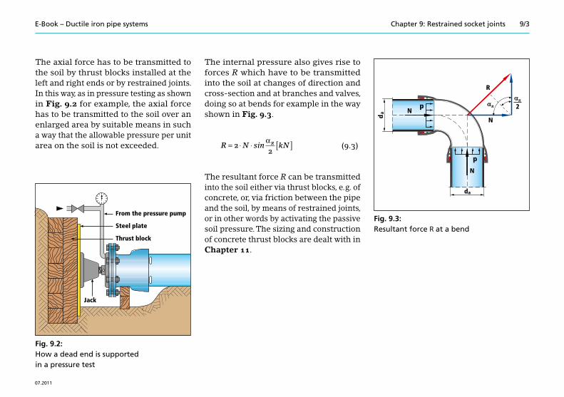
The axial force has to be transmitted to the soil by thrust blocks installed at the left and right ends or by restrained joints. In this way, as in pressure testing as shown in Fig. 9.2 for example, the axial force has to be transmitted to the soil over an enlarged area by suitable means in such a way that the allowable pressure per unit area on the soil is not exceeded.
Fig. 9.2:How a dead end is supported in a pressure test
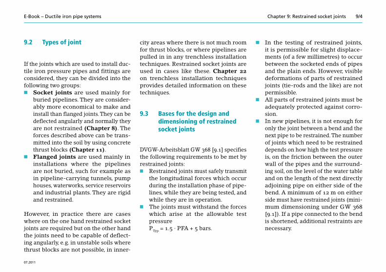
The internal pressure also gives rise to forces R which have to be transmitted into the soil at changes of direction and cross-section and at branches and valves, doing so at bends for example in the way shown in Fig. 9.3.
(9.3)
The resultant force R can be transmitted into the soil either via thrust blocks, e. g. of concrete, or, via friction between the pipe and the soil, by means of restrained joints, or in other words by activating the passive soil pressure. The sizing and construction of concrete thrust blocks are dealt with in Chapter 11.
Fig. 9.3:Resultant force R at a bend
��
�
�
�
�
��
��
�
����������������������
������������
����
����������
R N kNR= ⋅ ⋅ [ ]22
sinα
E-Book – Ductile iron pipe systems 9/4
07.2011
Chapter 9: Restrained socket joints
9.2 Types of joint
If the joints which are used to install duc-tile iron pressure pipes and fittings are considered, they can be divided into the following two groups:n Socket joints are used mainly for
buried pipelines. They are consider-ably more economical to make and install than flanged joints. They can be deflected angularly and normally they are not restrained (Chapter 8). The forces described above can be trans-mitted into the soil by using concrete thrust blocks (Chapter 11).
n Flanged joints are used mainly in installations where the pipelines are not buried, such for example as in pipeline-carrying tunnels, pump houses, waterworks, service reservoirs and industrial plants. They are rigid and restrained.
However, in practice there are cases where on the one hand restrained socket joints are required but on the other hand the joints need to be capable of deflect-ing angularly, e. g. in unstable soils where thrust blocks are not possible, in inner-
city areas where there is not much room for thrust blocks, or where pipelines are pulled in in any trenchless installation techniques. Restrained socket joints are used in cases like these. Chapter 22 on trenchless installation techniques provides detailed information on these techniques.
9.3 Bases for the design and dimensioning of restrained socket joints
DVGW-Arbeitsblatt GW 368 [9.1] specifies the following requirements to be met by restrained joints:n Restrained joints must safely transmit
the longitudinal forces which occur during the installation phase of pipe-lines, while they are being tested, and while they are in operation.
n The joints must withstand the forces which arise at the allowable test pressure
PTyp = 1.5 · PFA + 5 bars.
n In the testing of restrained joints, it is permissible for slight displace-ments (of a few millimetres) to occur between the socketed ends of pipes and the plain ends. However, visible deformations of parts of restrained joints (tie-rods and the like) are not permissible.
n All parts of restrained joints must be adequately protected against corro-sion.
n In new pipelines, it is not enough for only the joint between a bend and the next pipe to be restrained. The number of joints which need to be restrained depends on how high the test pressure is, on the friction between the outer wall of the pipes and the surround-ing soil, on the level of the water table and on the length of the next directly adjoining pipe on either side of the bend. A minimum of 12 m on either side must have restrained joints (mini-mum dimensioning under GW 368 [9.1]). If a pipe connected to the bend is shortened, additional restraints are necessary.
E-Book – Ductile iron pipe systems 9/5
07.2011
Chapter 9: Restrained socket joints
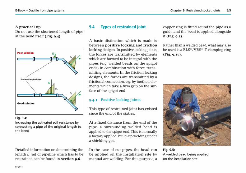
A practical tip:Do not use the shortened length of pipe at the bend itself (Fig. 9.4).
Fig. 9.4:Increasing the activated soil resistance by connecting a pipe of the original length to the bend
Detailed information on determining the length L [m] of pipeline which has to be restrained can be found in section 9.6.
9.4 Types of restrained joint
A basic distinction which is made is between positive locking and friction locking designs. In positive locking joints, the forces are transmitted by elements which are formed to be integral with the pipes (e. g. welded beads on the spigot ends) in combination with force-trans-mitting elements. In the friction locking designs, the forces are transmitted by a frictional connection, e.g. by toothed ele-ments which take a firm grip on the sur-face of the spigot end.
9.4.1 Positive locking joints
This type of restrained joint has existed since the end of the sixties.
At a fixed distance from the end of the pipe, a surrounding welded bead is applied to the spigot end. This is normally a factory applied build-up welding under a shielding gas.
In the case of cut pipes, the bead can be applied on the installation site by manual arc welding. For this purpose, a
copper ring is fitted round the pipe as a guide and the bead is applied alongside it (Fig. 9.5).
Rather than a welded bead, what may also be used is a BLS® / VRS®-T clamping ring (Fig. 9.15).
Fig. 9.5:A welded bead being applied on the installation site
�
���
��
�� �
�
�������������
�������������
�������������������� � �
E-Book – Ductile iron pipe systems 9/6
07.2011
Chapter 9: Restrained socket joints
In the case of fittings which have a spigot end, the bead which transmits force may also be integrally cast and machined. Its dimensions are the same as in the case of pipes of the nominal size concerned.
In the BAIO® positive locking system, the force-transmitting elements consist of integrally cast lugs on the spigot end and recesses in the sockets into which the lugs fit. The two parts are locked together by turning after the fashion of a bayonet joint. The system is used on fittings and valves.
Positive locking restrained joints with an internal retaining chamber
The positive locking joints with an inter-nal retaining chamber which are widely used at the moment are the BLS® / VRS®-T, the Universal Ve and the BAIO® push-in joints. They cannot be combined with one another because there are differences between the force-transmitting elements, the form of the welded bead and the dis-tance of the latter from the end of the pipe.
Positive locking restrained joints with an external retaining chamber
A design which has an external retain-ing chamber which has to be fixed sepa-rately to a collar on the socket is shown in Fig. 9.13. At the end face of the socket, the pipes have a collar extending round in a circle to which a ring containing the retaining chamber is fixed by means of hooked bolts. The longitudinal forces are transmitted from the welded bead on the spigot end, via a thrust-restraint ring, to the retaining chamber and from there via the hooked bolts to the socket of the next pipe.
Table 9.1 is an overview of the types of joint, their ranges of application and their allowable angular deflections.
Positive locking restrained joints with an internal retaining chamber
TIS-K® 100 –300 As stated by manufacturer 3
UNIVERSAL Ve 350–400
As stated by manufacturer
3
500–800 2
900 1,5
1000 1,2
1200 1,1
BLS® / VRS®-T 80–150
As stated by manufacturer
5
200 –300 4
400 3
500 3
600 2
800 –1000 1,5
BAIO® 80 –300 As stated by manufacturer ≤ 3,
Positive locking restrained joints with an external retaining chamber
Hydrotight 400 –500
As stated by manufacturer
3
600 –700 2
E-Book – Ductile iron pipe systems 9/8
07.2011
Chapter 9: Restrained socket joints
The TIS-K® system
In the TIS-K® restrained joint (Fig. 9.6), force is transmitted from one pipe to the next, or from a fitting, via the welded bead and the retaining ring, into the socket. The retaining ring is slit or in segments and is matched to the outside diameter of the pipes.The construction of the TIS-K® restrained push-in joint is the same for both pipes and fittings.
The joint still has the full original angular deflectability of the TYTON® joint (Table 9.1).
The UNIVERSAL Ve system
Longitudinal force is transmitted by the retaining ring of the TIS-K® sys-tem, whereas the gasket is part of the STANDARD system (form C under DIN 28603 [9.2]) (Fig. 9.7). The allowable angular deflections for pipes are given in Table 9.1.
Fig. 9.7:The UNIVERSAL Ve restrained push-in joint
The BLS® / VRS®-T system
The positive locking BLS® / VRS®-T sys-tem allows the two assembly operationsn make a seal, andn lock,to be broken down into two separate steps which have to be performed and checked one after the other. In the first step, the push-in joint (TYTON® or VRS®-T) is assembled. In a second step, it is then made restrained by the insertion of lock-ing elements.
In the nominal size range from DN 80 to DN 500, the locking elements are locks (Figs. 9.8 and 9.9), whereas from DN 600 to DN 1000 they are wide plate-like seg-ments (Fig. 9.10). In the case of the locks, a distinction has to be made between the “right” and “left” types and they have to be inserted as detailed in the installation instructions. When the assembly pro cess has been completed, a rubber catch is inserted in the opening in the socket face which is still open to prevent the locks from shifting (Fig. 9.9).
���������������������
���������� ��
Fig. 9.6:The TIS-K® restrained push-in joint
�������������������������������� ���
E-Book – Ductile iron pipe systems 9/9
07.2011
Chapter 9: Restrained socket joints
In the case of the DN 600 to DN 1000 nomi-nal sizes, the wide plate-like locking seg-ments are inserted in the axial direction through the twin openings in the socket face and are then evenly distributed around the circumference. The openings should preferably be positioned at the crest of the pipe to simplify the process of inserting the locks (Fig. 9.10).
Fig. 9.10:BLS® restrained push-in joint with insertion openings in the socket face and a clamping strap (DN 600 to DN 1000 nominal sizes)
Rubber catch
Insertion openings
TYTON® gasketWelded bead
Locking chamber
Locking segment
SpigotClamping strap
Socket
Fig. 9.8:BLS® / VRS®-T restrained push-in joint with locks (DN 80 to DN 500 nominal sizes)
Rubbercatch
Left lock Right lock
High-pressure lock
Fig. 9.9:Layout of the locks and the rubber catch in the BLS® / VRS®-T joint (DN 80 to DN 500 nominal sizes); high-pressure lock only for DN 80 to DN 250 nominal sizes
Right lock
Left lock
Lockingchamber
Welded bead
TYTON®/VRS®-T gasket
Socket
Socket face
E-Book – Ductile iron pipe systems 9/10
07.2011
Chapter 9: Restrained socket joints
Once the locking segments have all been inserted in the gap at the socket, they are all moved around the circumference until none of the humps on them can be seen through the openings in the socket and they are then fixed in place with a clamp-ing strap or a clamping clip (Fig. 9.11).
The BAIO® system
The positive locking BAIO® system is used for fittings and valves. On their outer face, the spigot ends carry four lugs evenly dis-tributed around the circumference, while the sockets have a retaining chamber whose front wall contains four receiving
openings which match the lugs on the spigot end. Once the spigot end has been inserted in the socket, it is turned through an eighth of a revolution and thus locked, on the bayonet principle.
Fig. 9.12 shows a positive locking BAIO® socket and the matching BAIO® spigot end of a dead end of the kind which is used as an end closure in a pressure test. For this purpose, the dead end has a screw-thread for a venting plug and two hand-levers to allow it to be turned.
The Hydrotight system
Fig. 9.13 is a cross-section through a joint of this kind when it has been completely assembled. Before the joint is assem-bled, the retaining ring (A) and the slit securing ring (B) are slid onto the spigot. When the joint has been made, the two rings are drawn up against the socket and screwed tight with the hooked bolts (C) and nuts (D). The joint is then extended so that all the force-transmitting members are resting against one another.
Fig. 9.11:Fixing in place of the locking segments by a clamping clip
Fig. 9.12:BIAO® system flanged socket (left) and spigot-ended dead end (right)
Fig. 9.13:Cross-section through the Hydrotight positive locking external joint
Hooked bolts (C)
Retaining ring (A) Nuts (D)
Securing ring (B)Socket face
Insertion openings
E-Book – Ductile iron pipe systems 9/11
07.2011
Chapter 9: Restrained socket joints
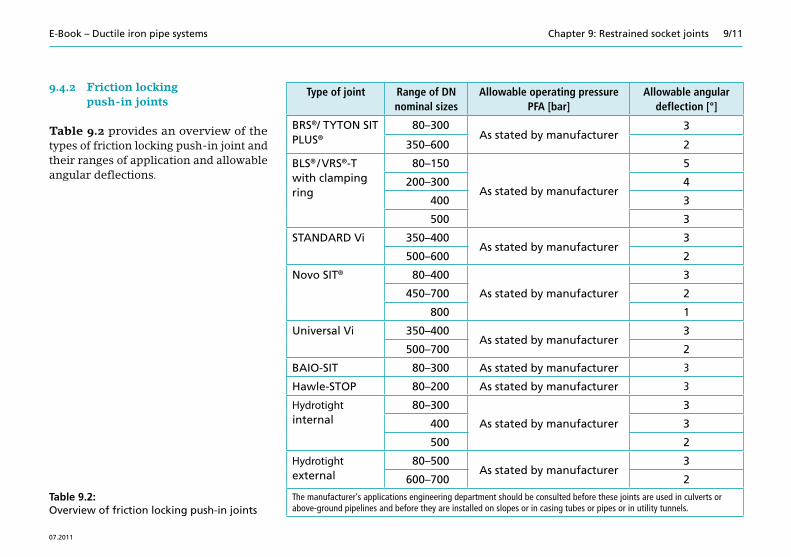
9.4.2 Friction locking push-in joints
Table 9.2 provides an overview of the types of friction locking push-in joint and their ranges of application and allowable angular deflections.
Table 9.2:Overview of friction locking push-in joints
Type of joint Range of DN nominal sizes
Allowable operating pressure PFA [bar]
Allowable angular deflection [°]
BRS®/ TYTON SIT PLUS®
80–300As stated by manufacturer
3
350–600 2
BLS® / VRS®-T with clamping ring
80–150
As stated by manufacturer
5
200–300 4
400 3
500 3
STANDARD Vi 350–400As stated by manufacturer
3
500–600 2
Novo SIT® 80–400
As stated by manufacturer
3
450–700 2
800 1
Universal Vi 350–400As stated by manufacturer
3
500–700 2
BAIO-SIT 80–300 As stated by manufacturer 3
Hawle-STOP 80–200 As stated by manufacturer 3
Hydrotight internal
80–300
As stated by manufacturer
3
400 3
500 2
Hydrotight external
80–500As stated by manufacturer
3
600–700 2
The manufacturer’s applications engineering department should be consulted before these joints are used in culverts or above-ground pipelines and before they are installed on slopes or in casing tubes or pipes or in utility tunnels.
E-Book – Ductile iron pipe systems 9/12
07.2011
Chapter 9: Restrained socket joints
The BRS® system
In this system, a TYTON SIT PLUS® gas-ket which has stainless steel segments vulcanised into it (Fig. 9.14) is used in place of the usual gasket. These segments have sharp, hardened teeth which cut into the surface of the end of the pipe.
Fig. 9.14:The BRS® friction locking push-in joint
The BLS® / VRS®-T systemwith a clamping ring
With this system, the application of welded beads to pipes which have been shortened on site can be dispensed with. Instead of the locks, two halves of a clamping ring are inserted in the insertion openings in the socket and are clamped onto the spigot end with bolts (Fig. 9.15).
Fig. 9.15:The BLS® / VRS®-T friction locking push-in joint with a clamping ring
On their inner side, the clamping rings have toothed pressure-applying surfaces. Under the rules shown below, their use is confined to buried pipelines and the rules also state that they may only be used in pipe sockets (Fig. 9.16).
Clamping rings should not be used for trenchless installation techniques or in culvert or bridge-carried pipelines or on slopes or in casing tubes or pipes or in utility tunnels.
E-Book – Ductile iron pipe systems 9/13
07.2011
Chapter 9: Restrained socket joints
The TYTON SIT PLUS® system
With the introduction of the TYTON SIT PLUS® system (Fig. 9.17) in 2003, the range of application of the Tyton SIT® friction locking joint was effectively wid-ened when it was replaced by the TYTON SIT PLUS® joint.
Fig. 9.17:The TYTON SIT PLUS®
friction locking push-in joint
����� ���������������������������� �
���������� ���� ��������������� �
��������������� �� ����
������� ��������������������������� ��
�� ���������������������������� ��
������� ��������������������������� ��
����������������������� �
�� ���������������������������� ��
� � �
��
�
� ������������������������� �
Fig. 9.16:Rules for the use of clamping rings
������������������������� ���� ��� �
E-Book – Ductile iron pipe systems 9/14
07.2011
Chapter 9: Restrained socket joints
The STANDARD Vi system
The STANDARD Vi system operates on a similar principle (Fig. 9.18). Stainless steel segments with hardened teeth which have been ground to a sharp edge are vul-canised into the STANDARD gasket. The teeth engage in the surface of the spigot end and thus transmit the longitudinal forces.
The Novo SIT® system
The socket has a integrally cast retaining chamber. In contrast to the TYTON SIT PLUS® system, the sealing and retaining functions are separate from one another. The design of the retaining ring causes it always to remain resting against the retaining chamber as the spigot end is inserted, which means that the travels for extending the joint are only short. (Fig. 9.19).
The UNIVERSAL Vi system
In this case too the sealing and longi-tudinal -force-transmitting functions are separate from one another. The retain-ing, i. e. transmitting, function is per-formed by the Novo SIT® ring whereas the STANDARD gasket does the sealing (Fig. 9.20).
Fig. 9.20:The UNIVERSAL Vi friction locking push-in joint
����������������������������� ����
������������������������
���������� ��
Fig. 9.18:The STANDARD Vi friction locking push-in joint
Fig. 9.19:The Novo SIT® friction locking push-in joint
������������������������
����������� ���
E-Book – Ductile iron pipe systems 9/15
07.2011
Chapter 9: Restrained socket joints
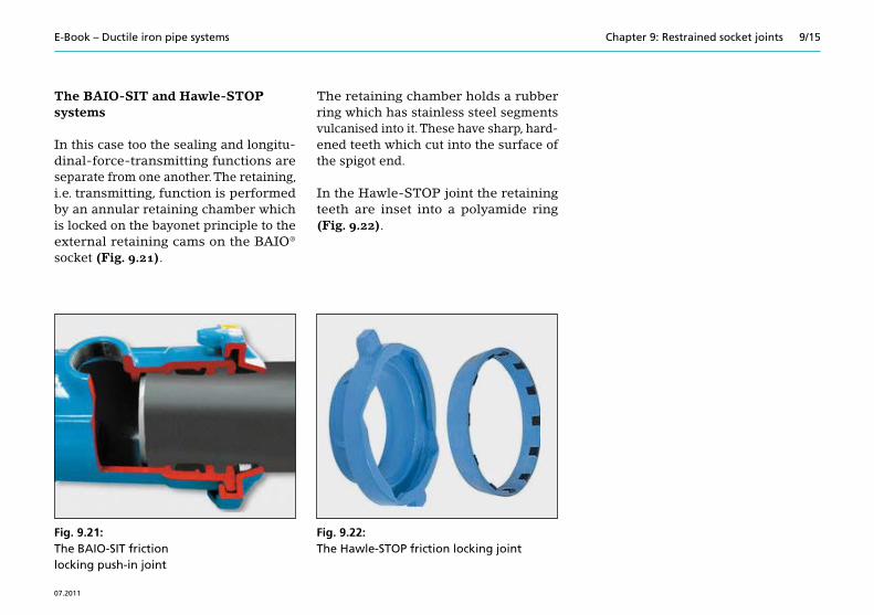
The BAIO-SIT and Hawle-STOP systems
In this case too the sealing and longitu-dinal-force-transmitting functions are separate from one another. The retaining, i.e. transmitting, function is performed by an annular retaining chamber which is locked on the bayonet principle to the external retaining cams on the BAIO® socket (Fig. 9.21).
The retaining chamber holds a rubber ring which has stainless steel segments vulcanised into it. These have sharp, hard-ened teeth which cut into the surface of the spigot end.
In the Hawle-STOP joint the retaining teeth are inset into a polyamide ring (Fig. 9.22).
Fig. 9.22:The Hawle-STOP friction locking joint
E-Book – Ductile iron pipe systems 9/16
07.2011
Chapter 9: Restrained socket joints
The Hydrotight internal system ( double-chambered socket)
There are two chambers extending round in a circle in the socket. One chamber holds the Hydrotight gasket while the thrust-restraint ring, an elastomer ring with toothed segments vulcanised into it, is seated in the second chamber. This ring also has a sealing lip which stops soil and moisture from penetrating into the joint. (Figs. 9.23 and 9.24).
The Hydrotight external system
A thrust-restraint ring of ductile iron is fastened to the external collar on the socket by hooked bolts. This ring, together with the socket face, creates a chamber in which an elastomer ring with toothed segments vulcanised into it is seated. This ring also has small sealing lips which stop soil and moisture from penetrating into the joint. The toothed segments transmit the longitudinal forces from the socket to the next pipe (Figs. 9.25 and 9.26).
Friction locking screwed-socket joints are used mainly for repairs. In the case of these joints a distinction is made between systems using locking elements and ones using a clamping ring.
In the case of the restrained screwed-socket joint which uses locking elements, the collar of the screwed ring, to which a wrench can be applied, contains tan-gential insertion passages, rectangular in cross-section, which are inclined in the inward direction in the opposite direc-tion to that in which the ring is screwed in. Toothed wedges are driven in through these insertion passages and these cut into the spigot end and produce a restrained joint (Fig. 9.27).
The screwed-socket systems which use a clamping ring exist in two variants: the variant using a single clamping ring (Fig. 9.28) and the variant using a special clamping ring (Fig. 9.29).
Table 9.3 provides an overview of the friction locking designs of screwed-socket joint and of their ranges of application, operating pressures and allowable deflec-tions.
Fig. 9.27:A restrained screwed-socket joint using locking elements
Fig. 9.28:A screwed-socket joint using a single clamping ring
Fig. 9.29:A screwed-socket joint using a special clamping ring
Screwed socket
Screwed ringLocking element
Slide ring
Rubber gasket
Screwed ring
Clamping ringSlide ring
Screwed socket
Rubber gasket Screwed socketRubber gasket
Special screwed ring
Slide ring
Clamping ring
Screwed ring
E-Book – Ductile iron pipe systems 9/18
07.2011
Chapter 9: Restrained socket joints
9.4.4 Clamps for retrospective fitting
The clamp consists of two or three iden-tical parts which are clamped together by bolts. The restraint is produced by the interaction between the retaining part, which engages behind the socket, and the toothed pressure-applying plates, which are pressed against the pipe. Clamps (type M) (Fig. 9.30) can be used for TYTON® joints and screwed-socket joints.
Clamps are fitted once the socket joint has been connected; the joint retains its full capacity for angular deflection.
Fig. 9.30:A restrained push-in joint fitted with clamps (type M)
The range of application of the type M clamp is shown in Table 9.4.
Table 9.4:Range of application of the type M clamp
Nominal size DN
Allowable oper-ating pressure
PFA [bar]
Angular deflection
[°]
80 – 300 As stated by manufacturer
3 400
9.5 Type tests
The manufacturer has to demonstrate the fitness for use of restrained joint systems by carrying out tests under EN 545 [9.3].
The requirements and testing conditions for this demonstration are dealt with in detail in Chapter 8 “Push-in joints”. For the “Tested” mark of the DVGW (German Technical and Scientific Association for Gas and Water) to be obtained, these fit-ness tests have to be carried out under external monitoring. In the final analysis, it is the details given in the manufactur-ers’ catalogues which determine the field of application of restrained joints.
Type of joint Range of DN nominal sizes
Allowable operating pressure PFA [bar]
Allowable angu-lar deflection [°]
Using locking elements 80–300 As stated by manufacturer 2
Using clamping ring 80–300 As stated by manufacturer 3
Using special clamping ring 300–400 As stated by manufacturer 3
Table 9.3:Range of application and angular deflectability of friction locking screwed-socket joints
E-Book – Ductile iron pipe systems 9/19
07.2011
Chapter 9: Restrained socket joints
9.6 Determining the forces which occur and the lengths of pipe to be restrained
At changes of direction and cross-section and at branches, the internal pressure generates forces which have to be trans-mitted into the ground.
In DVGW Arbeitsblatt GW 368 [9.1], detailed rules for calculating these forces are given and are printed there in the form of easily used tables for the standard cases. The most important steps in the cal-culation process will be explained below by taking a bend fitting as an example.
At the bend, a resultant force RN acts in the direction of the line bisecting the angle of the bend. The projected area of the bend acts on the compacted filling of the trench with this force. The pressure per unit area which this produces is generally higher than the compressive strength of the soil resting against the bend.
The soil deforms and the bend shifts in the direction of the resultant RN.
Because the pipe ends inserted in the sockets of the bend are locked but are able to deflect, the first two pipes undergo a sideways displacement when this shift in position occurs; as they are displaced, they activate the soil resistance E over their projected lateral area (diameter · length), as shown in Fig. 9.31.
(9.4)
For safety reasons, only two thirds of the length of the pipes is used in the equa-tion (Fig. 9.32).
�
�
��
�
��
��
�
�
�
�
��
Fig. 9.31:Activation of the soil resistance E by a shift of the bend on the line bisecting the angle
Fig. 9.32:Soil resistance E that is activated
Eall l DE
kNh
.
232
E-Book – Ductile iron pipe systems 9/20
07.2011
Chapter 9: Restrained socket joints
A practical tipThe shift of the bend which causes the soil resistance to be activated results in angular deflection of the two pipes in the sockets of the bend. If the two pipes are to deflect to a neutral angle, the shift of the bend can be anticipated by setting the two pipes to a negative deflection (Figs. 9.33 and 9.34).
The other restrained pipes which follow the two mentioned will only be displaced axially, when the skin friction R will be activated. This friction depends on the length L [m] of the restrained section of the pipeline and on the weights of the earth load, the pipe and the filling of water.
Frictional force from the earth load at the top of the pipe
The first frictional force R1 is deter mined from the earth load above the pipe (Fig. 9.35).
R G DE HB B1 kN/m
(9.5)
Frictional forces from the earth load, filling of water and weight of pipe at the underside of the pipe
The second frictional force R2, due to the earth load above the pipe and to the weight of the pipe and its filling of water, acts on the underside of the pipe (Fig. 9.35). The full length of the pipe is used in the calculation in this case.
��
Fig. 9.33:Anticipating the shift of the bend – negative angular deflections at the bend
Fig. 9.34:Negative angular deflections at a bend – Checking the shift of the bend to the neutral-angle position
E-Book – Ductile iron pipe systems 9/21
07.2011
Chapter 9: Restrained socket joints
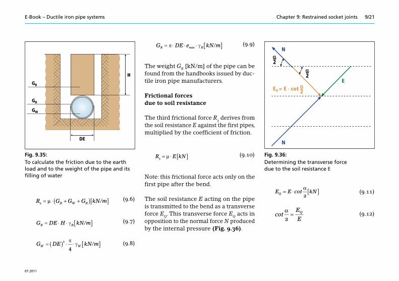
Fig. 9.35:To calculate the friction due to the earth load and to the weight of the pipe and its filling of water
(9.6)R G G GB W R2 = ⋅ + +( )[ ]μ kN/m
(9.7)G DE HB B kN/m
(9.8)G DEW W 2
4
kN/m
(9.9)G DE eR R min kN/m
The weight GR [kN/m] of the pipe can be found from the handbooks issued by duc-tile iron pipe manufacturers.
Frictional forces due to soil resistance
The third frictional force R3 derives from the soil resistance E against the first pipes, multiplied by the coefficient of friction.
(9.10)R E kN3 = ⋅ [ ]μ
Note: this frictional force acts only on the first pipe after the bend.
The soil resistance E acting on the pipe is transmitted to the bend as a transverse force EQ. This transverse force EQ acts in opposition to the normal force N produced by the internal pressure (Fig. 9.36).
(9.11)E E kNQ = ⋅ [ ]cotα2
(9.12)cot
α2
=E
EQ
�
��
��
��
��
���
�
�
���
�
����������������
Fig. 9.36:Determining the transverse force due to the soil resistance E
E-Book – Ductile iron pipe systems 9/22
07.2011
Chapter 9: Restrained socket joints
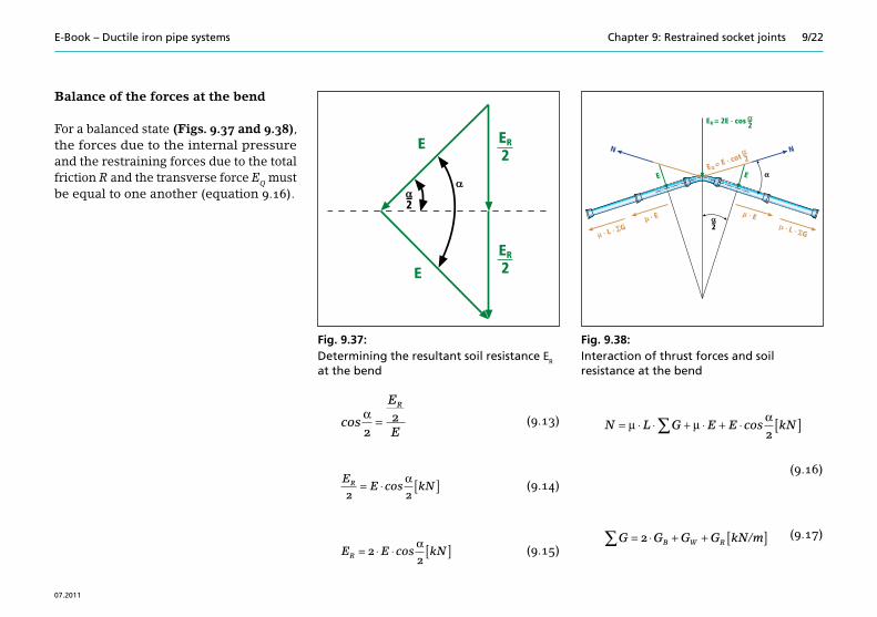
Balance of the forces at the bend
For a balanced state (Figs. 9.37 and 9.38), the forces due to the internal pressure and the restraining forces due to the total friction R and the transverse force EQ must be equal to one another (equation 9.16).
(9.13)cosα2
2=
E
E
R
(9.14)EE kNR
2 2= ⋅ [ ]cos
α
(9.15)E E kNR = ⋅ ⋅ [ ]22
cosα
N L G E E kN= ⋅ ⋅ + ⋅ + ⋅ [ ]∑μ μα
cos2
(9.16)
(9.17)G G G GB W R∑ = ⋅ + + [ ]2 kN/m
��
��
����������
���������������
�����
�
���
�����������������
������������
����
Fig. 9.38:Interaction of thrust forces and soil resistance at the bend
Fig. 9.37:Determining the resultant soil resistance ER at the bend
E-Book – Ductile iron pipe systems 9/23
07.2011
Chapter 9: Restrained socket joints
From this, the length L of pipeline which has to be restrained can be found.
Taking a pipe length of 6 m and the follow-ing values
γB = 18 kN/m3
γW = 10 kN/m3
γR = 70.5 kN/m3 (ductile cast iron)
the length L of pipeline which needs to be restrained can be calculated as follows for ductile iron water pipelines and for a system test pressure STP.
Where pipelines are within the water table, the resulting buoyancy reduces the forces due to weight and the soil resistance and hence the frictional force.Where installation takes place within the water table in cohesive soils and where there are cohesive soils of soft and stiff consistency which are difficult to compact (soil types B 2 to B 4 under GW 310 [9.4]), the coefficient of friction μ tends towards
zero. In these cases, it is recommended that the entire pipeline be safeguarded with restrained joints.At changes in direction in a vertical plane, the resultant force acts outwards at the outside of the bend. As a result the forces Gw and GR due to weight in equation 9.17 may tend towards zero.
DVGW Arbeitsblatt GW 368 [9.1] brings the results of these calculations together in tables, which saves one from having to do a vast amount of calculating work.For calculations which are not covered by the values in the tables, an online calculating program is available un- der “Tools for calculations”, button “DVGW GW 368“, on the www.eadips.org website of the European Association for Ductile Iron Pipe Systems · EADIPS® / Fachgemeinschaft Guss-Rohrsysteme (FGR®) e. V.
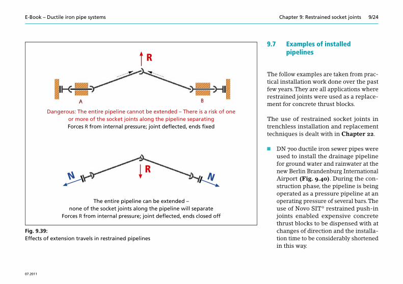
After installation, individual socket joints are often in an unextended state and make it necessary for extension to be performed before the ends of the pipeline are con-nected to fixed points (e. g. structures, bur-ied pipelines) (Fig. 9.39). The extension travels of the individual restrained joint systems are a few millimetres.
During the planning phase and in the course of installation, particular care must be taken to follow the manufacturer’s installation instructions and any special directions (Chapters 19 and 22).
The follow examples are taken from prac-tical installation work done over the past few years. They are all applications where restrained joints were used as a replace-ment for concrete thrust blocks.
The use of restrained socket joints in trenchless installation and replacement techniques is dealt with in Chapter 22.
n DN 700 ductile iron sewer pipes were used to install the drainage pipeline for ground water and rainwater at the new Berlin Brandenburg International Airport (Fig. 9.40). During the con-struction phase, the pipeline is being operated as a pressure pipeline at an operating pressure of several bars. The use of Novo SIT® restrained push-in joints enabled expensive concrete thrust blocks to be dispensed with at changes of direction and the installa-tion time to be considerably shortened in this way.
�
�� �
Dangerous: The entire pipeline cannot be extended – There is a risk of one or more of the socket joints along the pipeline separatingForces R from internal pressure; joint deflected, ends fixed
�
�� �
The entire pipeline can be extended –none of the socket joints along the pipeline will separate
Forces R from internal pressure; joint deflected, ends closed off
Fig. 9.39:Effects of extension travels in restrained pipelines
E-Book – Ductile iron pipe systems 9/25
07.2011
Chapter 9: Restrained socket joints
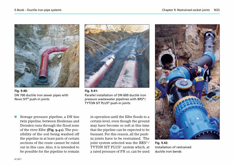
n Sewage pressure pipeline, a DN 600 twin pipeline, between Heidenau and Dresden runs through the flood zone of the river Elbe (Fig. 9.41). The pos-sibility of the soil being washed off the pipeline in at least parts of certain sections of the route cannot be ruled out in this case. Also, it is intended to be possible for the pipeline to remain
in operation until the Elbe floods to a certain level, even though the ground may have become so soft at this time that the pipeline can be expected to be buoyant. For this reason, all the push-in joints have to be restrained. The joint system selected was the BRS® / TYTON SIT PLUS® system which, at a rated pressure of PN 10, can be used
Fig. 9.41:Parallel installation of DN 600 ductile iron pressure wastewater pipelines with BRS® / TYTON SIT PLUS® push-in joints
Fig. 9.42:Installation of restrained ductile iron bends
Fig. 9.40:DN 700 ductile iron sewer pipes with Novo SIT® push-in joints
E-Book – Ductile iron pipe systems 9/26
07.2011
Chapter 9: Restrained socket joints
for nominal sizes of up to DN 600. The design of this system combines the sealing and retaining functions in a single ring.
n There was a shortage of time and installation space for the replacement and relaying of an old DN 1000 drink-ing water main in Leipzig (Fig. 9.42). The new pipelines were installed
throughout with restrained joints and because of this there was no need for expensive pressure-distributing walls (i. e. thrust blocks) to absorb the forces.
n 6 km of a DN 1200 trunk main needs to be renovated by lining it with cement mortar without the transportation of drinking water being interrupted. Sec-
tions 2 km long are being bypassed at a time by a DN 600 bypass pipeline of restrained ductile iron pipes mounted above ground (Fig. 9.43). Once the renovation work on the given section is completed, the ductile iron pipes are disconnected and used again for the next section, which is being done at least eight times. Max. test pressure for the bypass: 30 bars. Forces at the 45° bend: 720 kN. DN 600 pipes and fittings with BLS® push-in joints have been used (Fig. 9.10).
n Flangeless restrained gate valves with restrained sockets, and transition fit-tings to old pipelines of different mate-rials, were used to replace a complete gate-valve-equipped pipeline inter-section which had had conventional flanged gate valves. There were four gate valves and a hydrant and with the new components the number of indi-vidual parts dropped from 546 to 47; the installation time went down by a factor of 5 (Fig. 9.44).
Fig. 9.43:A DN 600 ductile iron bypass pipeline with BLS® push-in joints
Fig. 9.44:Renovation of a gate-valve-equipped pipe-line intersection with BAIO® restrained joints.
E-Book – Ductile iron pipe systems 9/27
07.2011
Chapter 9: Restrained socket joints
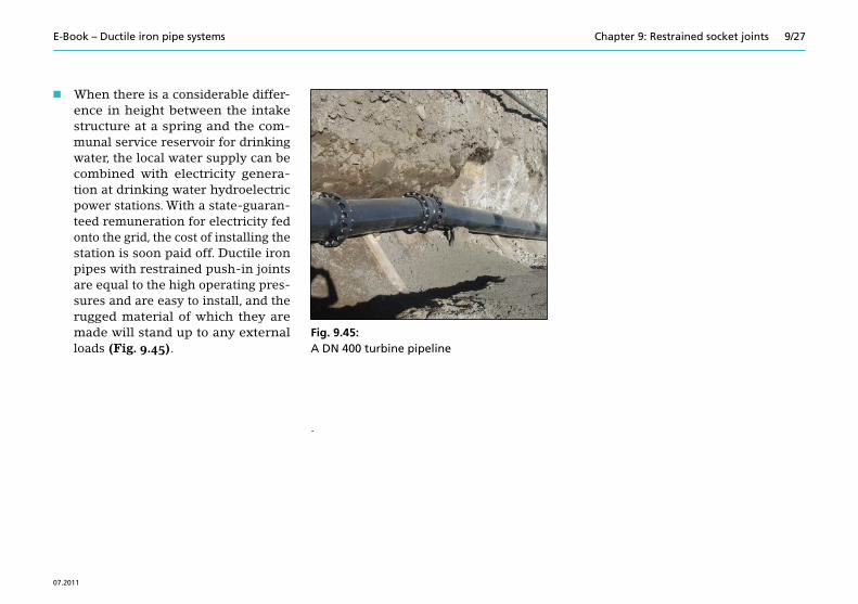
n When there is a considerable differ-ence in height between the intake structure at a spring and the com-munal service reservoir for drinking water, the local water supply can be combined with electricity genera-tion at drinking water hydroelectric power stations. With a state-guaran-teed remuneration for electricity fed onto the grid, the cost of installing the station is soon paid off. Ductile iron pipes with restrained push-in joints are equal to the high operating pres-sures and are easy to install, and the rugged material of which they are made will stand up to any external loads (Fig. 9.45).
.
Fig. 9.45:A DN 400 turbine pipeline
E-Book – Ductile iron pipe systems 9/28
07.2011
Chapter 9: Restrained socket joints
9.8 Notation in equations
DE = da [m]Outside diameter of pipe
DI = di [m]Inside diameter of pipe
emin [m]Minimum wall thickness depending on the choosen pipe type
E [kN]Soil resistance
ER [kN]Resultant soil resistance onthe line bisecting the angle
EQ [kN]Transverse force due tosoil resistance
GB [kN/m]Weight of the soil above the pipe
GR [kN/m]Force due to the weight of the pipe
GW [kN/m]Force due to the weight of the filling of water
H [m]Height of cover above the pipe
l [m]Length of pipe
L [m]Length of pipeline to be restrained
N (N’) [kN]Axial force due to internal pressure
p [bar]Internal pressure in a pipeline(1 bar = 100 kN/m2)
R [kN]Resultant force from theinternal pressure
R1 [kN/m]Frictional force from the earth load on the top of the pipeR2 [kN/m]Frictional force from the earth load, the filling of water and the weight of the pipe,
on the underside of the pipe
R3 [kN]Frictional force due to soil resistance
STP [kN/m2]System Test Pressure(1 bar = 100 kN/m2)
α [°]Angle of the bend
γB [kN/m3]Specific weight of the soil
γR [kN/m3]Specific weight of ductile iron
γW [kN/m3]Specific weight of water
μ Coefficient of friction between pipe and soil
all.σh [kN/m2]Allowable horizontal pressure on soil
E-Book – Ductile iron pipe systems 9/29
07.2011
Chapter 9: Restrained socket joints
9.9 References
[9.1] DVGW-Arbeitsblatt GW 368 Längskraftschlüssige Muffenverbin- dungen für Rohre, Formstücke und Armaturen aus duktilem Gusseisen oder Stahl [DVGW worksheet GW 368 Restrained socket joints for ductile iron and steel pipes, fittings and valves] 2002-06
[9.2] DIN 28603 Rohre und Formstücke aus duktilem Gusseisen – Steckmuffen-Verbindungen – Zusammenstellung, Muffen und Dichtungen [Ductile iron pipes and fittings – Push-in joints – Survey, sockets and gaskets] 2002-05
[9.3] EN 545 Ductile iron pipes, fittings, accessories and their joints for water pipelines – Requirements and test methods [Rohre, Formstücke, Zubehörteile aus duktilem Gusseisen und ihre Verbin- dungen für Wasserleitungen – Anforderungen und Prüfverfahren] 2010


![7 Valves - EADIPS FGR...defined in EN 736-1 [7.1-01]. Table 7.1.1-01 contains a classification of valves according to their functional features. Isolating valves are basically intended](https://static.documents.pub/doc/80x56/5e8819cfe68dc730af235aef/7-valves-eadips-fgr-defined-in-en-736-1-71-01-table-711-01-contains.jpg)


