We know that the kinetic energy can be converted to electrical energy. We are presenting in this paper that kinetic energy pro-duced by movement of vehicles on speed breaker of road, convert in electrical energy i.e., can produce power. Here in this paper we are looking forward to conserve the kinetic energy that gone wasted, while vehicles move. The number of vehicles passing over speed breaker on road is increasing day by day. Beneath speed breaker, setting up an electro-mechanical unit known to be power hump, could help us conserving this energy and use it for power generation. The electrical output can be improved by arranging these power humps in series. This generated power can be stored, by using different electrical devices. We can supply this
by also having solar panels that can provide power when needed while the vehicles were not moving.
BASIC PRINCIPLE
When moving, the vehicles possess some kinetic energy. This kinetic energy can be utilized to produce power by using a special arrangement called POWER HUMP. It is an Electro-Mechanical unit. It utilizes both mechanical technologies and electrical tech-niques for the power generation and its storage. POWER HUMP is a dome like device likely to be speed breaker. Whenever the vehicle is allowed to pass over the dome it gets pressed down-wards then the springs are attached to the dome is compressed and the rack which is attached to the bottom of the dome moves downward in reciprocating motion. Since the rack has teeth con-nected to gears, there exists conversion of reciprocating motion of rack into rotary motion of gears but the two gears rotate in
In the present days power has got a major importance in human life. Due to day by day increase in population and less of the
Keywords:
ABSTRACT
the energy uniform. So that the shafts will rotate with certain R.P.M. these shafts are connected through a belt drive to the dynamos, which converts the mechanical energy into electrical energy. The conversion wil
south and north poles, an E.M.F is induced in it. So, for inducing the E.M.F.armature coil has to rotate, for rotating this armature it is connected to a long shaft. By rotating same e.m.f is induced, for this rotation kinetic energy of moving vehicles is utilized. The power is generated in both the directions; to convert this power into one way, a special component is used called zener diode for continuous supply. All this mechanism can be housed under the dome, like speed breaker, which is called HUMP. The electrical output can be improved by arranging these POWER
stored by using different electrical devices.
A. Possible using different Mechanisms:-
1. Spring coil mechanism
2. Rack- Pinion mechanism
3. Crank-shaft mechanism
4. Roller mechanism
B. Rack and Pinion Mechanism
Speed breaker POWER GENERATOR Converters basically new concept of non-conventional energy generation. It is electro-mechanical energy generating machine. This machine converts reciprocating motion in to rotary motion. The rotational power
-ates electricity.
which is prime input in the system. For that we use weight of
MIT International Journal of Electrical and Instrumentation Engineering Vol. 4, No. 2, August 2014, pp. 90-93 91
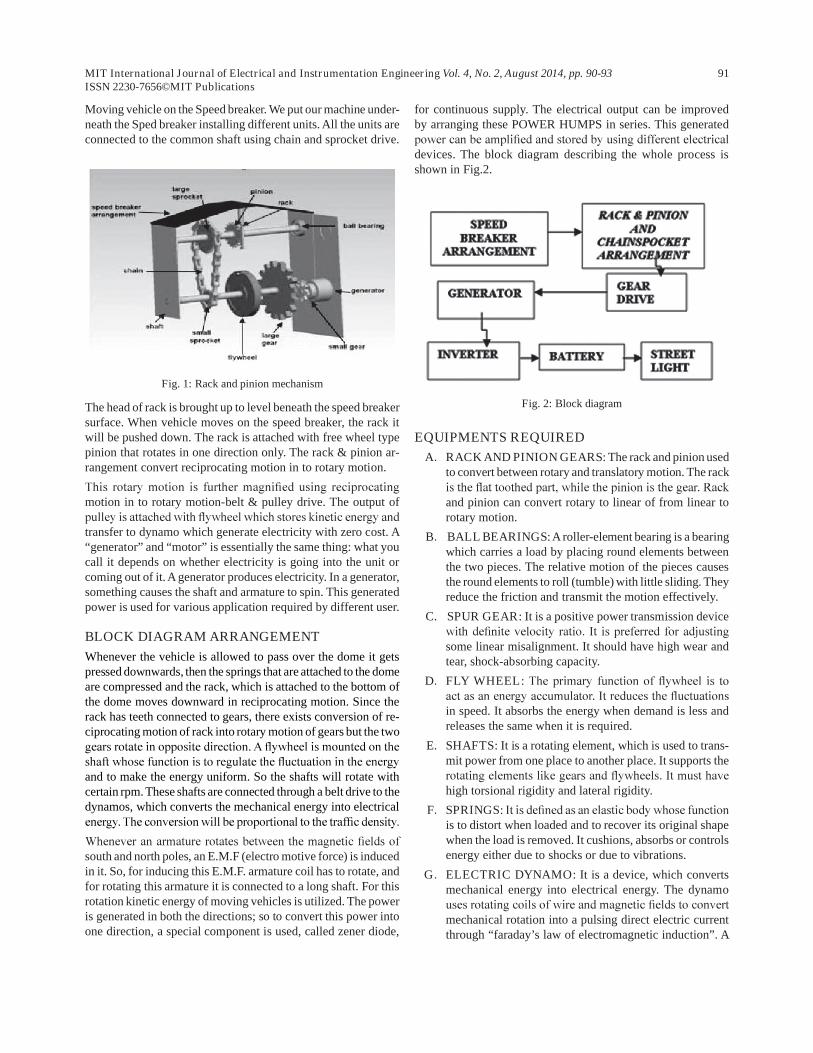
Moving vehicle on the Speed breaker. We put our machine under-neath the Sped breaker installing different units. All the units are connected to the common shaft using chain and sprocket drive.
Fig. 1: Rack and pinion mechanism
The head of rack is brought up to level beneath the speed breaker surface. When vehicle moves on the speed breaker, the rack it will be pushed down. The rack is attached with free wheel type pinion that rotates in one direction only. The rack & pinion ar-rangement convert reciprocating motion in to rotary motion.
motion in to rotary motion-belt & pulley drive. The output of
transfer to dynamo which generate electricity with zero cost. A “generator” and “motor” is essentially the same thing: what you call it depends on whether electricity is going into the unit or coming out of it. A generator produces electricity. In a generator, something causes the shaft and armature to spin. This generated power is used for various application required by different user.
BLOCK DIAGRAM ARRANGEMENT
Whenever the vehicle is allowed to pass over the dome it gets pressed downwards, then the springs that are attached to the dome are compressed and the rack, which is attached to the bottom of the dome moves downward in reciprocating motion. Since the rack has teeth connected to gears, there exists conversion of re-ciprocating motion of rack into rotary motion of gears but the two
and to make the energy uniform. So the shafts will rotate with certain rpm. These shafts are connected through a belt drive to the dynamos, which converts the mechanical energy into electrical
south and north poles, an E.M.F (electro motive force) is induced in it. So, for inducing this E.M.F. armature coil has to rotate, and for rotating this armature it is connected to a long shaft. For this rotation kinetic energy of moving vehicles is utilized. The power is generated in both the directions; so to convert this power into one direction, a special component is used, called zener diode,
for continuous supply. The electrical output can be improved by arranging these POWER HUMPS in series. This generated
devices. The block diagram describing the whole process is shown in Fig.2.
Fig. 2: Block diagram
EQUIPMENTS REQUIRED
A. RACK AND PINION GEARS: The rack and pinion used to convert between rotary and translatory motion. The rack
and pinion can convert rotary to linear of from linear to rotary motion.
B. BALL BEARINGS: A roller-element bearing is a bearing which carries a load by placing round elements between the two pieces. The relative motion of the pieces causes the round elements to roll (tumble) with little sliding. They reduce the friction and transmit the motion effectively.
C. SPUR GEAR: It is a positive power transmission device
some linear misalignment. It should have high wear and tear, shock-absorbing capacity.
D. FLY WHEEL
in speed. It absorbs the energy when demand is less and releases the same when it is required.
E. SHAFTS: It is a rotating element, which is used to trans-mit power from one place to another place. It supports the
high torsional rigidity and lateral rigidity.
F. SPRINGSis to distort when loaded and to recover its original shape when the load is removed. It cushions, absorbs or controls energy either due to shocks or due to vibrations.
G. ELECTRIC DYNAMO: It is a device, which converts mechanical energy into electrical energy. The dynamo
mechanical rotation into a pulsing direct electric current through “faraday’s law of electromagnetic induction”. A
MIT International Journal of Electrical and Instrumentation Engineering Vol. 4, No. 2, August 2014, pp. 90-93 92
dynamo machine consists of a stationary structure, called
of rotating winding called the armature which turns within
CIRCUIT DIAGRAM
established by Benjamin Franklin and still followed by most
conductors from the positive to the negative pole. In actuality,
to the positive pole. In the vast majority of applications, however,
discussion below the conventional model is retained.
B. IC1-CD4047
IC1-CD4047 consist of a gatable, astable multivibrator with logic techniques incorporated to permit positive or negative edge- triggered monostable multivibrator action with retriggering and external counting option.
C. AC TO 9V AC Transformer
As per our requirement in this circuit diagram we have use 230v ac to 9v ac. Transformer is a static device which converts electri-cal energy from higher voltage to lower voltage or vice versa.
BSERVATIONS
As far as the experiment concerns, we have two related observa-tions with regard to the voltage generated to the variations in speed and load. The following were the two illustrations:
(a). Let us consider the load (heavier vehicle) is constant on the speed breaker. Now we have the voltage produced, to the variations in the speed of the vehicle. If the vehicle runs slowly then it certainly applies the pressure on the speed breaker for a long time so the voltage produced will be most in this case. While we keep on increasing the speed, the vehicle rushes over the speed breaker, the pressure keep on decreasing so as the voltage produced. The graph plotted between these two variables, is shown Fig. 3.
Fig. 3: Voltage produced vs Speed of the vehicle
(b). Let us consider the speed (usually low) of the vehicle is kept constant on the speed breaker. Now we have the voltage produced, to the variations in the load (vehicles) applied on the speed breakers. Assume, if the vehicle that runs over it has the least load capacity compared to others then it certainly applies a very less pressure that result in a least voltage produced. Now as the load keep on increas-ing, the voltage produced also kept increasing because the pressure on breaker keeps increases with the load.
ADVANTAGES
Below is the list of advantages due to the usage of the technique mentioned in this paper.
a. Pollution free power generation.
b. Simple construction, mature technology and easy main-tenance.
c. No consumption of any fossil fuel which is non-renewable source of energy.
d. No fuel transportation required.
e. No external source is needed for power generation.
f. Energy available all year round.
CONCLUSION
In coming days, this will prove a great boon to the world, since it will save a lot of electricity of power plants that gets wasted in illuminating the street lights. As the conventional sources are depleting very fast, then it is time to think of alternatives. We got to save the power gained from the conventional sources for
big cities is more, causing a problem to human being. But this
of new technique called “power hump”. It has advantage that it does not utilize any external source. Now the time has come to put forward these types of innovative ideas, and researches should be done to upgrade their implication.
MIT International Journal of Electrical and Instrumentation Engineering Vol. 4, No. 2, August 2014, pp. 90-93 93
REFERENCES
1. Sharma, P.C., “Non-conventional power plants”, Public Printing Service, New Delhi, 2003.
2. Mukherjee, D. Chakrabarti, S., “Non-conventional power plants”, 2005.
3. Mukherjee, D. Chakrabarti, S. “Fundamentals of renewable energy systems”, New Age international limited publishers New Delhi, 2005.
4. Sharma, P.C., “Principles of renewable energy systems”, 2003.
5. Watts, G., “Effects of speed distribution on the Hormonoise model predictions”, Inter-noise Conference, Prague, 2004.
6. Shirley. “Smart road hump will smooth the way for safe drivers”, Providence Journal, November 11, 2005
7. Dr. Anders Brandt & MSc. John Granlund Swedish Road Administration. “Bus Drivers Exposure to Mechanical Shocks Due To Speed Bumps”. Society for Experimental Mechanics, IMAC 25th Conference and Exposition on Structural Dynamics 2008.
8. P.M. Anderson and A.A. Fouad, „Power System Control and Stability, Galgotia Publications.
9. “Power System Dynamics and Control, K.R.Padiyar, Interline Publishers Bangalore.
10. “Power System Stabilizers, by Mitsubishi Corporation-A release notes from Mitsubishi Co.
11. Hindman Sanchez, “Smart Stopping Speeders in the Community, Smart Speed Bumps reward safe drivers”.