20
1
1
2
Contents Page
Section 1: Installation and Operating Instructions 3
Valve Description 3 Valve Design 3 Safety Precautions 3 Unpacking and Storage 3 Product Identification 3 General Installation Info 4 Pre-installation Steps 4 Installation Instructions 5 Operating Instructions 6 Actuator Adjustment 6 General Maintenance 6 Section 2: Flange Bolt Selection Guide 7
Lug Style (Single Flange) 7 Double Flange (ISO 5752) 8 Double Flange (ANSI B16.10) 9 Section 3: Flange Gasket Selection Guide 10
Class 150 Valves 11 Class 300 Valves 11 Section 4: Maintenance and Repair 12
Service Centers 12 Valve Components 13 Replacement Parts 15 Terminology 15 Routine Maintenance 15 Removing Actuators 15 Packing Replacement 15 Cover Gasket Replacement 16 Removing the Valve from the Line 16 Disc Seal Replacement 16 Bushing Seal Replacement – Disassembly, inspection, and reassembly 17
Trouble-free Operation
XOMOX Series 9000 Severe Service Butterfly Valves have proven themselves with long-term, trouble-free service in a wide variety of applications.
Properly installed, adjusted, and operated, these valves should require minimum attention. Questions?
If there are any questions, contact your nearest XOMOX represent-ative, XOMOX Service Center, or the factory.
XOMOX Automation & Service Center addresses and phone numbers are listed on XOMOX’s web site at www.xomox.com. You may also contact the factory at (513) 745-6000. About this manual
This manual has been developed to assist the valve user in the inspection, storage, installation, operation, and general maint-enance and repair of the XOMOX Severe Service Butterfly Valve.
Following these recommend-ations will enhance the operating efficiency and extend the life of the valve. Read carefully
The following procedures and illustrations have been prepared to assist you in the installation, maintenance, and repair of your XOMOX Severe Service Butterfly Valves. Please read these instructions carefully.
Important Information
WARNING
READ THE INSTRUCTIONS BEFORE INSTALLING OR SERVICING VALVE. Failure to read and follow instructions carefully could result in death or serious injury.
MASSIVE LEAKAGE. DO NOT attempt to repair a valve or its accessories while pressurized! Death or serious injury could result.
CAUTION
These instructions have been prepared for valves as they are currently manufactured. If you have an older design valve that needs repair, contact either the factory or your nearest XOMOX Service Center to make sure you have the correct repair parts and instructions.
WARNING
© Copyright 2004 Xomox Corporation. All rights reserved. Xomox®, Tufline®, and Matrix®, are registered trademarks of Xomox Corporation. Xomox XRP™ is a trademark of Xomox Corporation.
3
Valve Description
The XOMOX Series 9000 Severe Service Butterfly Valve is available in three (3) body styles; lug (single flange) to API 609 Category B face-to-face dimen-sions, double flanged to ISO 5752 Table 4 Short Pattern end-to-end dimensions, and double flanged to ASME B16.10 Long Pattern gate valve replacement (GVR) end-to-end dimensions. All three (3) styles are covered in this manual.
The Severe Service Butterfly Valve is available with a laminated metal seal of 321 stainless steel and graphite and with a variety of body, disc shaft, and trim component materials. All seat and material configurations are covered in this manual. Valve Design
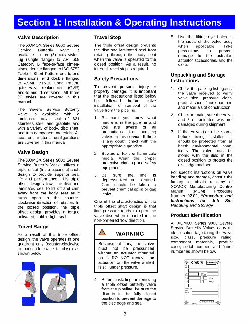
The XOMOX Series 9000 Severe Service Butterfly Valve utilizes a triple offset (triple eccentric) shaft design to provide superior seal life and performance. This triple offset design allows the disc and laminated seal to lift off and cam away from the body seat as it turns open in the counter-clockwise direction of rotation. In the closed position, the triple offset design provides a torque activated, bubble-tight seal. Travel Range
As a result of this triple offset design, the valve operates in one quadrant only (counter-clockwise to open, clockwise to close) as shown below.
Travel Stop
The triple offset design prevents the disc and laminated seal from rotating through the body seat when the valve is operated to the closed position. As a result, no internal travel stop is required. Safety Precautions
To prevent personal injury or property damage, it is important that the precautions listed below be followed before valve installation, or removal of the valve from the pipeline.
1. Be sure you know what media is in the pipeline and you are aware of all precautions for handling valves in this service. If there is any doubt, check with the appropriate supervisor.
2. Beware of toxic or flammable media. Wear the proper protective clothing and safety equipment.
3. Be sure the line is depressurized and drained. Care should be taken to prevent chemical spills or gas leaks.
One of the characteristics of the triple offset shaft design is that line pressure tends to open the valve disc when mounted in the non-preferred flow direction.
4. Before installing or removing a triple offset butterfly valve from the pipeline, be sure the disc is in the fully closed position to prevent damage to the disc edge and seal.
5. Use the lifting eye holes in
the sides of the valve body when applicable. Take precautions to prevent damage to the actuator, actuator accessories, and the valve.
Unpacking and Storage Instructions
1. Check the packing list against the valve received to verify valve size, pressure class, product code, figure number, and materials of construction.
2. Check to make sure the valve and / or actuator was not damaged during shipment.
3. If the valve is to be stored before being installed, it should be protected from all harsh environmental cond-itions. The valve must be stored with the disc in the closed position to protect the disc edge and seal.
For specific instructions on valve handling and storage, consult the factory to obtain a copy of XOMOX Manufacturing Control Manual (MCM) Procedure Number 02.02, “Procedure and Instructions for Job Site Handling and Storage”. Product Identification
All XOMOX Series 9000 Severe Service Butterfly Valves carry an identification tag stating the valve size, class, pressure rating, component materials, product code, serial number, and figure number as shown below.
Section 1: Installation & Operating Instructions
Because of this, the valve must not be pressurized without an actuator mounted on it. DO NOT remove the actuator from the valve while it is still under pressure.
WARNING

4
Replacement Parts
When ordering replacement parts, supply the six (6) or eight (8) digit product code number, the valve size and class, the valve figure number, and the valve serial number to insure the correct parts are delivered.
If the product code number can not be found, the following information must be provided: • Valve size and class • Body and disc materials • Valve serial number • Valve figure number • Valve service • Shaft diameter
Recommended replacement parts are indicated with asterisks (*) in the valve components table on page 14. General Installation Information
The XOMOX Series 9000 Severe Service Butterfly Valve in sizes 3” through 24” is designed to fit between standard ANSI pipe flanges, Classes 150 and 300, meeting ASME B16.5 flange specifications.
All valves are also designed to accommodate the use of standard non-metallic gaskets as specified by ASME B16.21, or standard spiral-wound metallic gaskets as specified by API 601.
Sheet gaskets may be of a suitable material of 1/16” (0.062”) thickness or less, meeting the dimensional requirements of ASME B16.21.
For recommended flange gasket dimensions, see page 11.
The XOMOX Series 9000 Severe Service Butterfly Valve can be installed in the pipeline with the shaft in the vertical, horizontal, or other intermediate diagonal position.
Based on service experience, media with concentrations of solid or abrasive particles, or media subject to solidification build-up, valve performance and service life will be enhanced by mounting the valve with the shaft in the horizontal position.
XOMOX Series 9000 Severe Service Butterfly Valves are bi-directional and can be mounted in the pipeline in either flow direction, however, the preferred flow direction for this valve is with the body seat positioned down-stream (shaft upstream). Each valve is supplied with a preferred flow direction arrow located on the identification tag.
Pre-installation Steps
1. Remove the protective flange face covers from the valve.
2. Inspect the valve to be certain the waterway is free from dirt and foreign matter. Be certain the adjoining pipeline is free from any foreign material such as rust, pipe scale, or welding slag that could damage the disc seal and body seating surfaces.
3. Mount the actuator on the valve prior to installation in the pipeline to facilitate the proper settings of the actuator travel stops.
4. Rotate the disc to the closed position.
5. Cycle the valve to the fully open position, then back to the fully closed position, checking the actuator travel stop settings for proper disc seal contact with the body seat.
6. Check the valve identification tag for pressure class, materials of construction, and operating pressure to be sure they are correct for the application.
READ AND THOROUGHLY UNDERSTAND THESE INSTRUCTIONS before installing or using this product. Failure to follow the proper instructions could invalidate the warranty and result in death, serious injury, or property damage. If there are any questions, contact the factory.
CAUTION
DO NOT use thick elastomeric gaskets. External leakage may occur.
Make sure the open and closed positions of the actuator correspond to the counter-clockwise to open rotation of the valve. Death, serious injury, and severe property damage could result.
CAUTION
DO NOT use the actuator’s closed position travel stop to limit disc rotation. Back the travel stop out at least three (3) full turns and lock it in place after the disc seal has made contact with the body seat.
WARNING
WARNING

5
7. Check the flange bolts or
studs for proper size, threading, and length. For suggested flange bolt sizes, see pages 7, 8, and 9.
8. The valve is now ready to be installed.
Installation Instructions
Installing All Style Valves:
1. Fully close the valve.
2. Noting the flow direction arrow on the valve identi-fication tag, place the valve between the flanges, making sure the body seat is located downstream and the shaft is located upstream.
3. Install the lower flange bolts loosely, leaving space for the flange gaskets.
4. After inserting the flange gaskets, one on each side of the valve, install the remaining flange bolts.
5. Using the sequence shown in Figure 1-1, tighten the flange bolts evenly to assure uniform gasket compression.
6. If an actuator is to be used, air hoses or electrical lines should be connected to the unit as specified by the actuator manufacturer.
7. The valve is now ready for operation.
EXPLOSION! DO NOT INSTALL VALVE WHERE SERVICE CONDITIONS EXCEED THE VALVE RATINGS. Death or serious injury could result or the warranty could become invalid. If there are any questions, contact the factory.
The preferred flow direction for all seal and body styles is with the body seat located downstream (shaft upstream) to provide maximum shutoff.
CAUTION
Make sure the valve is in the fully closed position when installing the valve between flanges. Damage to the disc edge and seal may occur and cause through-line leakage.
Figure 1-1
CAUTION
VALVE DAMAGE. Center the valve between the flanges and gaskets. Failure to center the valve may result in the disc striking the flange, gasket, or pipe, and may damage the disc edge, seal, and shaft.
ACCIDENTAL VALVE OPER-ATION! All valves placed in dead end service where the downstream side is exposed to atmosphere must be utilized with locking devices on manual gear actuators. Failure to provide locking devices could result in death or serious injury due to accidental valve operation.
WARNING
WARNING WARNING
6
Operating Instructions
Gear Operated Valves:
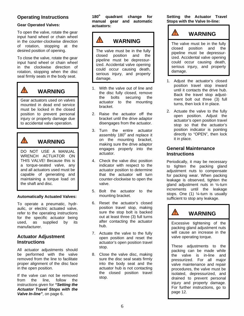
To open the valve, rotate the gear input hand wheel or chain wheel in the counter-clockwise direction of rotation, stopping at the desired position of opening.
To close the valve, rotate the gear input hand wheel or chain wheel in the clockwise direction of rotation, stopping when the disc seal firmly seats in the body seat.
Automatically Actuated Valves:
To operate a pneumatic, hydr-aulic, or electric actuated valve, refer to the operating instructions for the specific actuator being used, as supplied by its manufacturer. Actuator Adjustment Instructions
All actuator adjustments should be performed with the valve removed from the line to facilitate proper alignment of the disc face in the open position.
If the valve can not be removed from the line, follow the instructions given for “Setting the Actuator Travel Stops with the Valve In-line”, on page 6.
180o quadrant change for manual gear and automatic actuators:
1. With the valve out of line and the disc fully closed, remove the bolts securing the actuator to the mounting bracket.
2. Raise the actuator off the bracket until the drive adaptor disengages from the actuator.
3. Turn the entire actuator assembly 180o and replace it on the mounting bracket, making sure the drive adaptor engages properly into the actuator.
4. Check the valve disc position indicator with respect to the actuator position to determine that the actuator will turn counter-clockwise to open the valve.
5. Bolt the actuator to the mounting bracket.
6. Reset the actuator’s closed position travel stop, making sure the stop bolt is backed out at least three (3) full turns after contacting the actuator hub.
7. Actuate the valve to the fully open position and reset the actuator’s open position travel stop.
8. Close the valve disc, making sure the disc seal seats firmly into the body seat and the actuator hub is not contacting the closed position travel stop.
Setting the Actuator Travel Stops with the Valve In-line: 1. Adjust the actuator’s closed
position travel stop inward until it contacts the drive hub. Back the travel stop adjust-ment bolt out three (3) full turns, then lock it in place.
2. Actuate the valve to the fully open position. Adjust the actuator’s open position travel stop so that the actuator’s position indicator is pointing directly to “OPEN”, then lock it in place.
General Maintenance Instructions
Periodically, it may be necessary to tighten the packing gland adjustment nuts to compensate for packing wear. When packing leakage is observed, tighten the gland adjustment nuts in ¼-turn increments until the leakage stops. One (1) ¼-turn is usually sufficient to stop any leakage.
Gear actuators used on valves mounted in dead end service must be locked in the closed position to prevent personal injury or property damage due to accidental valve operation.
The valve must be in the fully closed position and the pipeline must be depressur-ized. Accidental valve opening could occur causing death, serious injury, and property damage.
DO NOT USE A MANUAL WRENCH ACTUATOR ON THIS VALVE! Because this is a torque-seated valve, any and all actuators used must be capable of generating and maintaining a torque load on the shaft and disc.
The valve must be in the fully closed position and the pipeline must be depressur-ized. Accidental valve opening could occur causing death, serious injury, and property damage.
Excessive tightening of the packing gland adjustment nuts will cause an increase in the valve operating torque. These adjustments to the packing can be made while the valve is in-line and pressurized. For all major valve maintenance and repair procedures, the valve must be isolated, depressurized, and drained to prevent personal injury and property damage. For further instructions, go to page 12.
WARNING
WARNING
WARNING WARNING
WARNING

7
Suggested flange bolt selection tables are shown on the next three (3) pages for the XOMOX Series 9000 Severe Service Butterfly Valve in lug and both double-flanged body styles. Note: When using spiral wound metallic gaskets with lug style valves, add .12” to the bolt lengths provided.
Flange Configurations
Class 150 and Class 300 in sizes 3” through 24” …… Are designed to fit between ASME B16.5-2003 raised face and flat face weld neck flanges.
For flange configurations other than ASME B16.5-2003, consult the factory.
Bolt Standards
Flange bolting lengths given in this guide are based on valve body face-to-face and flange thicknesses conforming to the following industry specifications:
Lug Style Body – API 609, Category B Valves MSS SP-68
Double Flanged Body – ISO 5752, Table 4, Short ASME B16.10, Tables 1 and 2
Flange thicknesses conform to ASME B16.5-2003, Class 150 and Class 300.
Section 2: Flange Bolt Selection Guide
Flange Bolt Selection Guide for Series 9100 Lug Style (Single Flange) Valves API 609, Category B
3” – 16” Class 150 and 3” – 8” Class 300 have threaded flange holes through the entire body. 18” – 24” Class 150 and 10” – 24” Class 300 have four (4) blind flange hole locations straddling the shaft that require shorter hex head bolts.
8
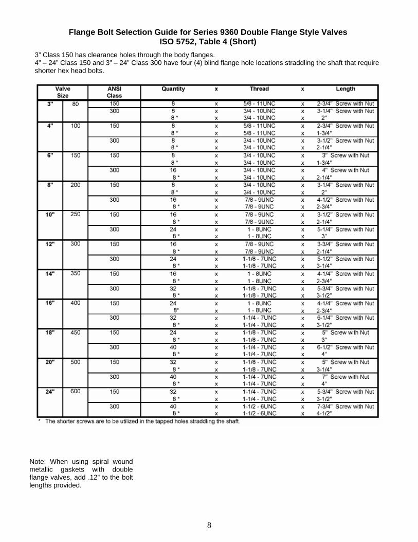
Note: When using spiral wound metallic gaskets with double flange valves, add .12” to the bolt lengths provided.
Flange Bolt Selection Guide for Series 9360 Double Flange Style Valves ISO 5752, Table 4 (Short)
3” Class 150 has clearance holes through the body flanges. 4” – 24” Class 150 and 3” – 24” Class 300 have four (4) blind flange hole locations straddling the shaft that require shorter hex head bolts.
9
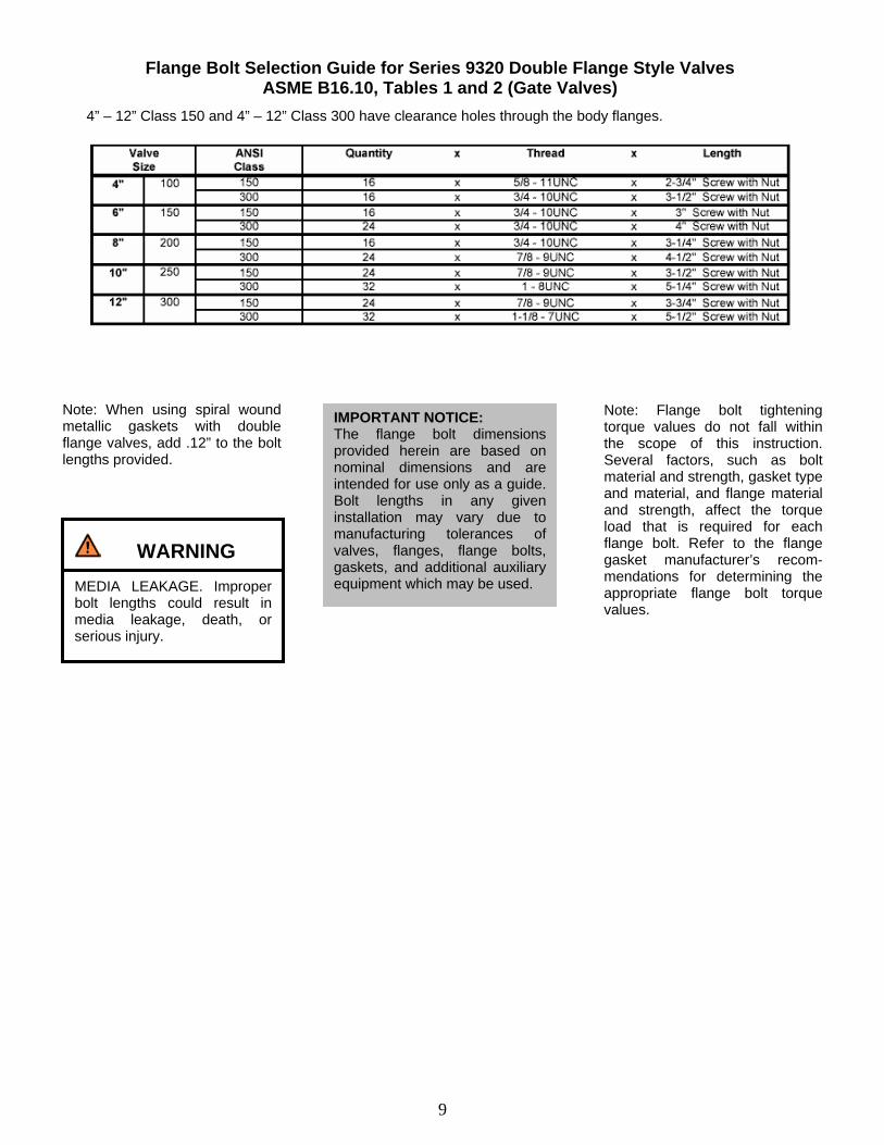
Note: When using spiral wound metallic gaskets with double flange valves, add .12” to the bolt lengths provided.
Note: Flange bolt tightening torque values do not fall within the scope of this instruction. Several factors, such as bolt material and strength, gasket type and material, and flange material and strength, affect the torque load that is required for each flange bolt. Refer to the flange gasket manufacturer’s recom-mendations for determining the appropriate flange bolt torque values.
Flange Bolt Selection Guide for Series 9320 Double Flange Style Valves ASME B16.10, Tables 1 and 2 (Gate Valves)
4” – 12” Class 150 and 4” – 12” Class 300 have clearance holes through the body flanges.
WARNING
MEDIA LEAKAGE. Improper bolt lengths could result in media leakage, death, or serious injury.
IMPORTANT NOTICE: The flange bolt dimensions provided herein are based on nominal dimensions and are intended for use only as a guide. Bolt lengths in any given installation may vary due to manufacturing tolerances of valves, flanges, flange bolts, gaskets, and additional auxiliary equipment which may be used.

10
XOMOX Series 9000 Severe Service Butterfly Valves are designed for use with either non-metallic sheet or spiral-wound metallic flange gaskets in all sizes 3” through 24”, in Classes 150 and 300. The flange gasket sealing surfaces on all valve sizes and styles provide a gasket contact area of 100% for optimum sealing performance.
The dimensions provided in the tables on the following page are recommended to utilize the maximum sealing capability of the gaskets.
However, they are suggested only as a guide. Gasket dimensions in any given installation may vary due to manufacturing tolerances. Flange Configurations
Class 150 and Class 300 in sizes 3” through 24” …… Are designed to fit between ASME B16.5-2003 raised face and flat face weld neck flanges.
For flange configurations other than ASME B16.5-2003, consult the factory.
Non-metallic Gaskets
For all valve sizes 3” through 24”, the valve faces are designed to accommodate the use of non-metallic sheet gaskets as specified by ASME B16.21.
To minimize the chances of flange gasket misalignment, it is suggested that non-metallic gaskets with outside diameter dimensions extending out to the flange bolts be used.
Non-metallic sheet gaskets thicker than 1/16 of an inch (0.062”) are not recommended.
Spiral-wound Metallic Gaskets
For all valve sizes 3” through 24”, the valve faces are designed to accommodate the use of spiral-wound metallic gaskets as specified by API 601.
To minimize the chances of flange gasket misalignment, it is suggested that spiral-wound metallic gaskets with outer centering rings extending out to the flange bolts be used.
Section 3: Flange Gasket Selection Guide
CAUTION
DO NOT use thick elastomeric gaskets or other gaskets of a rubber-like consistency. External leakage may occur.
IMPORTANT NOTICE: The flange gasket dimensions provided herein are based on nominal dimensions and are intended for use only as a guide. Gasket dimensions in any given installation may vary due to manufacturing tolerances of valves, flanges, flange bolts, gaskets, and additional auxiliary equipment which may be used.

11
Flange Gasket Selection Guide for Series 9000 Valves Non-metallic and Metallic Flange Gasket Dimensions
(1) Dimensions per ASME B16.21. Gaskets thicker than 1/16” are not recommended. (2) Dimensions per API 601.
12
Service Center Capabilities
Before attempting field repair of severe service butterfly valves, consider sending them to a XOMOX or Crane Service Center for repair.
Specialized equipment and experienced personnel at all XOMOX and Crane Service Centers can often provide repairs more economically than repairs performed in the field. New Valve Warranty
Valves repaired at XOMOX and Crane Service Centers are tested to the same specifications as new valves, and they carry the standard new valve warranty.
Automation and Service Centers
XOMOX Automation & Service Center addresses and phone numbers are listed on XOMOX’s web site at www.xomox.com. You may also contact the factory at (513) 745-6000. Crane Service Center addresses and phone numbers are listed on Crane Valve’s web site at www.cranevalve.com.
Contents Page Section 4: Maintenance and Repair 12
Valve Components 13 Replacement Parts 15 Terminology 15 Routine Maintenance 15 Removing Actuators 15 Packing Replacement 15 Cover Gasket Replacement 16 Removing the Valve from The Line 16 Disc Seal Replacement 16 Bushing Seal Replacement – Disassembly, inspection, and reassembly 17
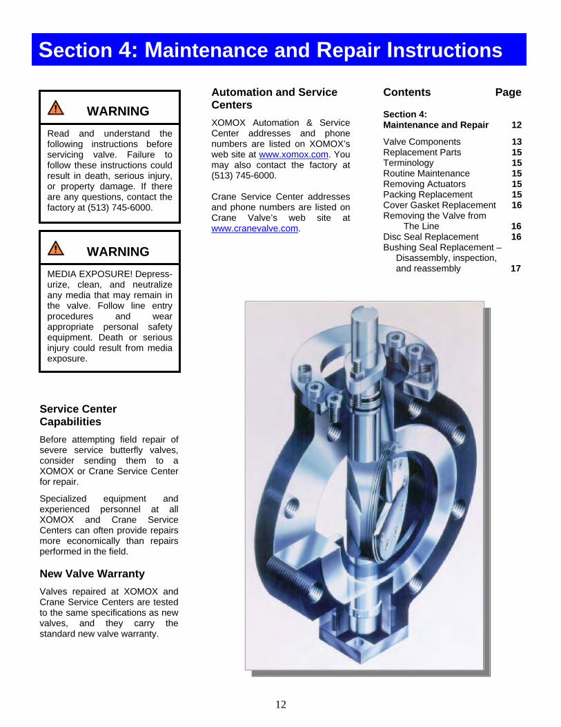
Section 4: Maintenance and Repair Instructions
WARNING
Read and understand the following instructions before servicing valve. Failure to follow these instructions could result in death, serious injury, or property damage. If there are any questions, contact the factory at (513) 745-6000.
WARNING
MEDIA EXPOSURE! Depress-urize, clean, and neutralize any media that may remain in the valve. Follow line entry procedures and wear appropriate personal safety equipment. Death or serious injury could result from media exposure.

13
XOMOX Series 9000 Severe Service Butterfly Valve Components –
Figure 4-1: Lug Style (Single Flange) Valves
Figure 4-2: Double Flange Valves – ISO 5752
14
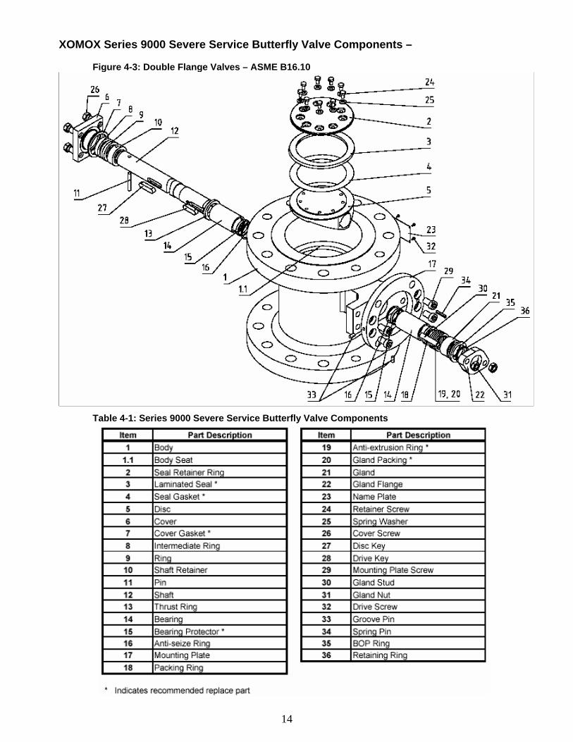
XOMOX Series 9000 Severe Service Butterfly Valve Components –
Figure 4-3: Double Flange Valves – ASME B16.10
Table 4-1: Series 9000 Severe Service Butterfly Valve Components
15
Replacement Parts
When ordering replacement parts, supply the six (6) or eight (8) digit product code number, the valve size and class, the valve figure number, and the valve serial number to insure the correct parts are delivered.
If the product code number can not be found, the following information must be provided: • Valve size and class • Body and disc materials • Valve serial number • Valve figure number • Valve service • Shaft diameter
Recommended replacement parts are indicated with asterisks (*) in the valve components table listed above. All recommended replace-ment parts for your XOMOX Series 9000 Severe Service Butterfly Valve are available from an authorized XOMOX distributor as a repair kit. Terminology
In the following instructions:
The drive end of the body refers to the end with the actuator mounting pad.
The front face of the body is the side containing the body seat.
The face of the disc is the flat face containing the seal cavity. Routine Maintenance
Periodically, it may be necessary to tighten the packing gland adjustment nuts to compensate for packing wear. When packing leakage is observed, tighten the adjustment nuts in ¼-turn increments until the leakage stops.
One (1) ¼-turn is usually sufficient to stop any leakage.
Excessive tightening of the packing gland adjustment nuts will cause an increase in valve torque.
These adjustments to the packing can be made while the valve is in-line and under pressure.
Removing the Actuator from the Valve
Enclosed gear and automatic actuators should be removed by unbolting the mounting bracket fasteners from the valve mounting pad, leaving the actuator firmly bolted to the bracket. Remove the drive adaptor from the valve shaft, if necessary. Packing Replacement
1. Loosen and remove the packing gland adjustment nuts and gland flange.
2. If the valve is equipped with a shaft retaining ring: Remove the retaining ring with a snap ring expansion tool, then remove the BOP ring.
3. Remove the gland to expose the upper ring of the shaft packing.
4. Using a proper packing extraction tool, remove the worn packing set from the packing chamber, taking care not to scratch the valve shaft or packing chamber wall. Do not remove the metal packing ring located at the bottom of the packing chamber.
5. Clean the valve packing chamber thoroughly, making sure all remnants of the worn packing set are removed.
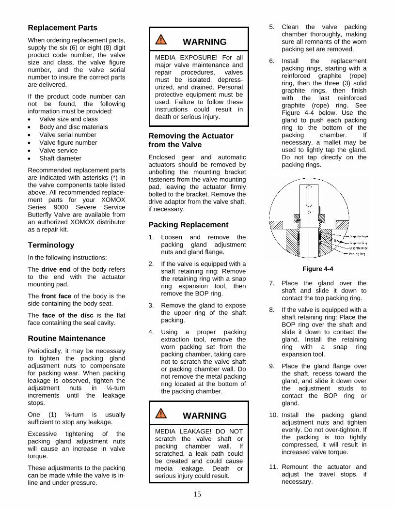
6. Install the replacement packing rings, starting with a reinforced graphite (rope) ring, then the three (3) solid graphite rings, then finish with the last reinforced graphite (rope) ring. See Figure 4-4 below. Use the gland to push each packing ring to the bottom of the packing chamber. If necessary, a mallet may be used to lightly tap the gland. Do not tap directly on the packing rings.
7. Place the gland over the
shaft and slide it down to contact the top packing ring.
8. If the valve is equipped with a shaft retaining ring: Place the BOP ring over the shaft and slide it down to contact the gland. Install the retaining ring with a snap ring expansion tool.
9. Place the gland flange over the shaft, recess toward the gland, and slide it down over the adjustment studs to contact the BOP ring or gland.
10. Install the packing gland adjustment nuts and tighten evenly. Do not over-tighten. If the packing is too tightly compressed, it will result in increased valve torque.
11. Remount the actuator and
adjust the travel stops, if necessary.
WARNING
MEDIA EXPOSURE! For all major valve maintenance and repair procedures, valves must be isolated, depress-urized, and drained. Personal protective equipment must be used. Failure to follow these instructions could result in death or serious injury.
WARNING
MEDIA LEAKAGE! DO NOT scratch the valve shaft or packing chamber wall. If scratched, a leak path could be created and could cause media leakage. Death or serious injury could result.
Figure 4-4
16
Cover Gasket Replace-ment
1. Loosen and remove the cover plate bolts and cover plate.
2. Remove the old cover gasket and thoroughly clean the cover plate and body sealing surface, making sure all the remnants of the old gasket are removed.
3. For lug style valves: Place the replacement cover gasket against the cover plate, lining up the bolt holes in the gasket with the bolt holes in the cover. For double flange style valves: Place the replace-ment spiral-wound gasket in the cover plate gasket groove.
4. Place the cover plate on the body sealing surface, gasket against the body.
5. Install the cover plate bolts, using Loctite Thread Locker, tightening them evenly in a crossing pattern. Firmly tighten the bolts.
Removing the Valve from the Line
1. Check the line to be sure it is completely isolated, depress-urized, and drained.
Wear protective clothing and equipment as dictated for the media. All standard safety precautions must be followed.
2. The valve must be in the fully closed position to prevent
damage to the disc edge and seal.
3. Disconnect all power and air supply lines to the actuator, if any.
4. Loosen all flange bolts, removing only the bolts necessary to release the valve from the line.
5. Remove the valve from the line and place in on blocks with the disc seal retainer ring facing up.
6. Decontaminate and clean the valve before performing any maintenance and repair work.
Disc Seal Replacement
1. Loosen and remove the seal retainer ring screws and spring washers.
2. Remove the seal retainer ring and worn seal.
3. Thoroughly clean the disc and retainer ring surfaces, making sure all the remnants of the old seal gasket are removed.
4. Stand the valve up on edge on a table or workbench surface.
5. Rotate the valve disc to the fully open position with the actuator, making sure the seal retainer ring groove in the disc is facing upward.
6. Place the new seal gasket over the disc, aligning the gasket so the mark shows to the angular side of the cone-seat of the body.
7. Place the laminated seal in the disc seal groove, making sure the seal is oriented with the largest ring down.
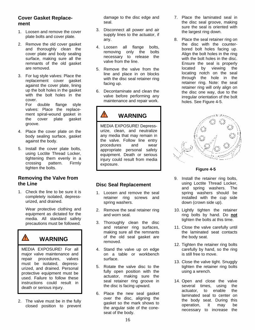
8. Place the seal retainer ring on the disc with the counter-bored bolt holes facing up. Align the bolt holes in the ring with the bolt holes in the disc. Ensure the seal is properly located by viewing the locating notch on the seal through the hole in the retainer ring. Note: the seal retainer ring will only align on the disc one way, due to the irregular orientation of the bolt holes. See Figure 4-5.
9. Install the retainer ring bolts,
using Loctite Thread Locker, and spring washers. The spring washers should be installed with the cup side down (crown side up).
10. Lightly tighten the retainer ring bolts by hand. Do not tighten the bolts at this time.
11. Close the valve carefully until the laminated seat contacts the body seat.
12. Tighten the retainer ring bolts carefully by hand, so the ring is still free to move.
13. Close the valve tight. Snuggly tighten the retainer ring bolts using a wrench.
14. Open and close the valve
several times, using the actuator, to enable the laminated seal to center on the body seat. During this operation, it may be necessary to increase the
WARNING
MEDIA EXPOSURE! For all major valve maintenance and repair procedures, valves must be isolated, depress-urized, and drained. Personal protective equipment must be used. Failure to follow these instructions could result in death or serious injury.
WARNING
MEDIA EXPOSURE! Depress-urize, clean, and neutralize any media that may remain in the valve. Follow line entry procedures and wear appropriate personal safety equipment. Death or serious injury could result from media exposure.
Figure 4-5

17
seating force during each operation to ensure the laminated seal aligns properly with the body seat. Normally five (5) operations is sufficient.
15. Tighten the retainer ring bolts, in a crossing pattern, using a torque wrench. Tighten the bolts to the appropriate torque value listed in Table 4-2.
16. The valve is now ready for testing.
17. After testing, the valve should set aside for a minimum of 24 hours in the tightly closed position.
18. A minimum of twenty-four (24) hours after completing valve assembly and testing, re-tighten the seal clamp plate bolts, using a torque wrench, to the specified torque values listed in Table 4-2. Bolts must be tightened in a crossing pattern.
Bushing Seal Replace-ment
Valve Disassembly:
1. Loosen and remove the packing gland adjustment nuts and gland flange.
2. If the valve is equipped with a shaft retaining ring: Remove the retaining ring with a snap ring expansion tool, then remove the BOP ring and the gland.
3. Loosen and remove the cover plate bolts and cover plate.
4. Loosen and remove the seal retainer ring screws and spring washers.
5. Remove the seal retainer ring and worn seal.
6. Facing the drive end of the valve, push the shaft into the valve until the entire upper
drive key appears through the key access slot in the disc.
7. Remove the upper drive key through the slot in the disc.
8. Pull the shaft out of the valve until the entire lower drive key appears through the key access slot in the disc.
9. Remove the lower drive key through the slot in the disc.
Note: 3” – 6” valves have only one (1) drive key.
10. Push the shaft into the valve until the shaft retainer ring and retainer pin are fully visible on the lower end of the valve.
11. Remove the intermediate
ring, graphite rings, retainer pin, and shaft retainer ring from the shaft.
12. Pull the shaft out of the body from the drive end, making sure the disc is completely supported.
13. Remove the worn packing set and metallic packing ring from the upper packing chamber.
Table 4-2 Seal Retainer Ring Bolt Tightening Torque Values
Valve Size Valve Class Bolt Size Tightening Torque
150 3” (DN 80) 300 M6 88 in-lbs
150 4” (DN 100) 300 M6 88 in-lbs
150 5” (DN 125) 300 M6 88 in-lbs
150 6” (DN 150) 300 M6 88 in-lbs
150 8” (DN 200) 300 M6 88 in-lbs
150 10” (DN 250) 300 M6 88 in-lbs
150 12” (DN 300) 300 M8 212 in-lbs
150 14” (DN 350) 300 M10 398 in-lbs
150 16” (DN 400) 300 M10 398 in-lbs
150 18” (DN 450) 300 M12 531 in-lbs
150 20” (DN 500) 300 M12 531 in-lbs
150 24” (DN 600) 300 M16 1,283 in-lbs
CAUTION
While pulling the shaft from the valve, do not allow the disc to drop out of the waterway. Damage to the disc may result.
18
14. Remove the worn bearing protectors from the upper and lower bushings.
15. Thoroughly clean each valve component, making sure all remnants of the old seal and cover gaskets are removed.
Components Inspection:
1. Inspect each reusable part for damage or signs of wear.
2. Check the body seat surface for scratches or galling which might cause through-line leakage.
3. Clean the body seat surface carefully. If necessary, polish the surface with 400-grit abrasive paper in a circum-ferencial direction.
4. It is advisable to replace all parts indicated as “recom-mended replacement parts” on page 14.
5. The cover gasket must be replaced after the seal is broken.
Reassembly:
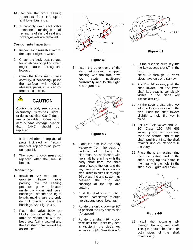
1. Install the 2.5 mm square graphite filament rope packing into the bearing protector grooves located inside the upper and lower bushings. Trim the packing to length, making sure the ends do not overlap inside the bushings. See Figure 4-6.
2. Place the valve body on blocks positioned flat on a table or workbench with the body seat facing upward and the top shaft bore toward the assembler.
3. Insert the bottom end of the
shaft part way into the upper bushing with the disc drive key seats positioned horizontally and to the right. See Figure 4-7.
4. Place the disc into the body
waterway from the back or underside of the body. The disc must be positioned with the shaft bore in line with the body shaft bore, the shaft bore offset to the left, and the key seats down. For stainless steel discs in sizes 8” through 24”, place the anti-seize rings between the disc and bushings at the top and bottom.
5. Push the shaft inward until it passes completely through the disc and upper bearing.
6. Rotate the disc clockwise 90o to position the key access slot (A) upward.
7. Rotate the shaft 90o clock-wise until the upper key seat is visible in the disc’s key access slot (A). See Figure 4-8.
8. Fit the first disc drive key into
the key access slot (A) in the disc.
Note: 3” through 6” valve sizes have only one (1) key.
9. For 8” – 24” valves, push the shaft inward until the lower shaft key seat is completely visible in the disc’s key access slot (A).
10. Fit the second disc drive key into the key access slot in the disc. Push the shaft inward slightly to hold the key in place.
11. For 12” – 24” valves and 6” – 10” Class 150 API 609 valves, place the thrust ring over the bottom end of the shaft, pushing it into the shaft retainer ring counter-bore in the body.
12. Place the shaft retainer ring over the bottom end of the shaft, lining up the holes in the ring with the hole in the shaft. See Figure 4-9 below.
13. Install the retaining pin
through the ring and shaft. The pin should be flush on both sides of the shaft retainer ring.
CAUTION
Control the body seat surface accurately. Scratches, nicks, or dents less than 0.040” deep are acceptable. Bodies with seat surface damage deeper than 0.040” should be replaced.
Figure 4-6
Figure 4-7
Figure 4-8
Figure 4-9

19
14. Press the shaft into the body until the shaft retainer ring locates against the anti-seize ring at the bottom of the lower body counter-bore.
15. For valve sizes larger than 12”, install graphite rope packing rings and the intermediate ring over the bottom end of the shaft.
16. For all lug style valves – Place the cover gasket and cover plate against the bottom surface of the body. Install the four cover plate bolts, using Loctite Thread Locker, into the threaded holes in the body, firmly tightening the bolts evenly in a crossing pattern. See Figure 4-10.
For all double-flanged style valves – Place the spiral-wound cover seal in its locating groove in the cover plate. Place the cover and seal against the bottom surface of the body. Install the four cover plate bolts, using Loctite Thread Locker, into the threaded holes in the body, firmly tightening the bolts evenly in a crossing pattern.
16. 17. Moving to the drive end of
the valve, install the components of the packing chamber in the following order: • Metal packing ring • (1) carbon filament yarn
rope packing ring • (3) graphite packing rings • (1) carbon filament yarn
rope packing ring • Metal gland • BOP ring • BOP snap ring / circlip
18. See Figure 4-11. Make sure the cut ends of the carbon filament yarn rope packing rings are located approx-imately 180o apart.
19. Place the gland flange over
the shaft and adjustment studs. Install the two gland adjustment nuts. Do not tighten the nuts at this time.
20. Fasten the actuator mounting plate to the body mounting pad using the four socket head cap screws provided. Firmly tighten the four screws. See Figure 4-12.
21. The actuator should be
mounted on the valve to provide an adequate seating force. See Page 6 for the proper actuator mounting instructions.
22. Stand the valve up on its right edge on a table or workbench surface.
23. Rotate the valve disc to the fully open position using the actuator, making sure the seal retainer ring groove in the disc is facing upward.
24. Place the new seal gasket over the disc, aligning the gasket so the mark shows to the angular side of the cone-seat of the body.
25. Place the laminated seal in the disc seal groove, making sure the seal is oriented with the largest ring down.
26. Place the seal retainer ring on the disc with the counter-bored bolt holes facing up. Align the bolt holes in the ring with the bolt holes in the disc. Ensure the seal is properly located by viewing the locating notch on the seal through the hole in the retainer ring. Note: the seal retainer ring will only align on the disc one way, due to the irregular orientation of the bolt holes. See Figure 4-13.
27. Install the retainer ring bolts,
using Loctite Thread Locker, and spring washers. The spring washers should be installed with the cup side down (crown side up).
28. Lightly tighten the retainer ring bolts by hand. Do not tighten the bolts at this time.
29. Close the valve carefully until the laminated seat contacts the body seat.
30. Tighten the retainer ring bolts carefully by hand, so the ring is still free to move.
31. Close the valve tight. Snuggly tighten the retainer ring bolts using a wrench.
Figure 4-10
Figure 4-11
Figure 4-12
Figure 4-13
20
32. Open and close the valve several times, using the actuator, to enable the laminated seal to center on the body seat. During this operation, it may be necessary to increase the seating force during each operation to ensure the laminated seal aligns properly with the body seat. Normally five (5) operations is sufficient.
Product Responsibility XOMOX’s concern for product performance extends to the product’s period of service. We feel it is important for users to also be aware of their respons-ibilities. Our products are man-ufactured and used in numerous applications with a wide variety of service conditions. While general guidelines are often furnished, it obviously is not possible to provide complete and specific performance data for every conceivable service condition. PN335970 – 06/04 USA
33. Tighten the retainer ring bolts, in a crossing pattern, using a torque wrench. Tighten the bolts to the appropriate torque value listed in Table 4-2.
34. Tighten the gland adjustment nuts. Do not over-tighten. If the packing is too tightly compressed, it will result in increased valve torque.
35. The valve is now ready for testing.
Therefore, the end user must assume final responsibility for proper evaluation, application, and performance of all products. The contents of this document are presented for information pur-poses only. Every effort has been made to ensure accuracy. This information is not intended to be construed as warranties or guarantees, expressed or implied, nor imply use applicability, for products or services described herein. We reserve the right to modify or improve the designs and
36. After testing, the valve should set aside for a minimum of 24 hours in the tightly closed position.
37. A minimum of twenty-four (24) hours after completing valve assembly and testing, re-tighten the seal clamp plate bolts, using a torque wrench, to the specified torque values listed in Table 4-2. Bolts must be tightened in a crossing pattern.
and specifications of such prod-ucts at any time and without notice. As the manufacturer, XOMOX sells its products and services pursuant to its standard terms and conditions of sale, including its limited warranty, copies of which are available on request. XOMOX limits its liability spec-ifically to the replacement or repair of defective items, or to a refund for same. XOMOX does not accept liability for any incident or consequential damages.


