without the express written consent of Harbor Freight Tools.
For technical questions, please call 1-800-444-3353.
SKU 90300 For technical questions, please call 1-800-444-3353. PAGE 2
PRODUCT SPECIFICATIONS
Item DescriptionElectrical Requirements 4,500W Maximum Output; 4,000W Continuous Output
20 AMPs @ 120V / 20 AMPs @ 240V 60 Hz Output 120V Dual Outlet: 20 AMP, 3 Prong Grounded 120/240V Outlet: 20 AMP, 4 Prong Twistlock (L14-20) Overload Protection: Two 20 AMP Circuit Breakers Battery Type Required: 12V with at least 24Ah capacity (not included) Battery Size Capacity: 8" L x 5-1/4" W x 7-1/2 to 8" Tall
Engine Type 9 HP Robin® /Subaru® EX Series with Electric Start 4 Cycle / 265 CC Displacement Model #EX-27052020
Alternator Two Pole / Single Phase / 60 Hz
Fuel Tank 6.5 Gallon
Estimated Run Time 14.5 Hours (w/ Full Tank @ 1/2 Load)
Overall Dimensions 29-3/4” x 25-1/2” x 20-5/8”
Weight 155 Pounds
THIS GENERATORIS NOT INTENDED TO POWERSENSITIVE ELECTRONICEQUIPMENT WITHOUT THEADDITION OF AN APPROPRIATELINE CONDITIONER (SOLDSEPARATELY).
REV 12/03; 02/04; 05/04; REV 03/06
This product requires oil and fuel to be added before starting.Attempting to start the engine without oil WILL ruin the engine andvoid the warranty.Fill the engine with the following:1.15 qt. of SAE 15W/40 oil
6.5 Gal. of unleaded gasoline with no oil added
Before starting the engine, refer to the engine owner’s manual for additional enginemaintenance information.
SAVE THIS MANUAL
You will need this manual for the safety warnings and precautions, operating, in-spection, maintenance and cleaning procedures, parts list and assemblydiagram. Keep your invoice with this manual. Write the invoice number on the insideof the front cover. Keep this manual and invoice in a safe and dry place for futurereference.
UNPACKINGWhen unpacking, check to make sure all the parts shown on the Parts List on page 18 areincluded. If any parts are missing or broken, please call Harbor Freight Tools at the numbershown on the cover of this manual as soon as possible.
Call Harbor Freight Tools at 1-800-444-3353for all technical questions and all inquiresregarding GENERATOR AND ENGINEreplacement parts.
SKU 90300 For technical questions, please call 1-800-444-3353. PAGE 3
GENERAL SAFETY RULES
WARNING!
READ AND UNDERSTAND ALL INSTRUCTIONSFailure to follow all instructions listed below may result in
electric shock, fire, and/or serious injury.SAVE THESE INSTRUCTIONS
WORK AREA
1. Keep your work area clean and well lit. Cluttered benches and dark areas inviteaccidents.
2. Do not operate generators in explosive atmospheres, such as in the presenceof flammable liquids, gases, or dust. Generators create sparks which may ignitethe dust or fumes.
3. Keep bystanders, children, and visitors away while operating a generator.Provide barriers or shields as needed.
ELECTRICAL SAFETY
4. Grounded tools must be plugged into an outlet properly installed and groundedin accordance with all codes and ordinances. Never remove the groundingprong or modify the plug in any way. Do not use any adapter plugs. Checkwith a qualified electrician if you are in doubt as to whether the outlet is properlygrounded. If the tools should electrically malfunction or break down, groundingprovides a low resistance path to carry electricity away from the user.
5. Double insulated tools are equipped with a polarized plug (one blade is widerthan the other). This plug will fit in a polarized outlet only one way. If the plugdoes not fit fully in the outlet, reverse the plug. If it still does not fit, contact aqualified electrician to install a polarized outlet. Do not change the plug in anyway. Double insulation eliminates the need for the three wire grounded powercord and grounded power supply system.
6. Avoid body contact with grounded surfaces such as pipes, radiators, ranges,and refrigerators. There is an increased risk of electric shock if your body isgrounded.
SKU 90300 For technical questions, please call 1-800-444-3353. PAGE 4
7. Do not expose generators to rain or wet conditions. Water entering a generatorwill increase the risk of electric shock.
8. Do not abuse Power Cords. Never use a Power Cord to carry any tool or pullthe Plug from an outlet. Keep Power Cords away from heat, oil, sharp edges,or moving parts. Replace damaged Power Cords immediately. Damaged PowerCords increase the risk of electric shock.
9. When operating a power tool outside, use an outdoor extension cord marked“W-A” or “W”. These extension cords are rated for outdoor use, and reduce therisk of electric shock.
PERSONAL SAFETY
10. Stay alert. Watch what you are doing, and use common sense when operatinga generator. Do not use a generator while tired or under the influence ofdrugs, alcohol, or medication. A moment of inattention while operating generatorsmay result in serious personal injury.
11. Dress properly. Do not wear loose clothing or jewelry. Contain long hair.Keep your hair, clothing, and gloves away from moving parts. Loose clothes,jewelry, or long hair can be caught in moving parts.
12. Avoid accidental starting. Be sure the ON/Off Switch is in its OFF position andthe ignition key is removed from the Ignition Switch (45) when the generator is notin use.
13. Remove adjusting keys or wrenches before turning the generator on. A wrenchor an adjusting key that is left attached to a rotating part of the generator may resultin personal injury.
14. Do not overreach. Keep proper footing and balance at all times.
15. Use safety equipment. Always wear eye protection. Dust mask, nonskid safetyshoes, hard hat, or hearing protection must be used for appropriate conditions.
16. Never run the generator in an enclosed garage or any other type of enclosedstructure without a proper, leak-free ventilation shaft. Carbon Monoxide, anodorless, colorless deadly gas may accumulate and cause serious injury or death.
17. Do not overload the generator. Use the correct generator for your application.The correct generator will do the job better and safer at the rate for which it isdesigned.
18. Do not use the generator if the Power Switch does not turn it on or off. Anygenerator that cannot be controlled with the Power Switch is dangerous and mustbe properly repaired or replaced.
GENERATOR USE AND CARE
SKU 90300 For technical questions, please call 1-800-444-3353. PAGE 5
19. Disconnect the negative battery cable from the battery and remove the IgnitionKey before making any adjustments, changing accessories, or storing thegenerator. Such preventive safety measures reduce the risk of starting the generatoraccidentally.
20. Store idle generators out of reach of children and other untrained persons.Generators are dangerous in the hands of untrained users.
21. Maintain generators with care. Do not use a damaged generator. Tag damagedgenerators “Do not use” until repaired.
22. Check for misalignment or binding of moving parts, breakage of parts, andany other condition that may affect the generator’s operation. If damaged,have the generator serviced before using. Many accidents are caused by poorlymaintained generators.
23. Use only accessories that are recommended by the manufacturer for yourmodel. Accessories that may be suitable for one generator may become hazardouswhen used on another generator.
GENERATOR USE AND CARE (Continued)
SERVICE
24. Generator service must be performed only by qualified repair personnel.Service or maintenance performed by unqualified personnel could result in a riskof injury.
25. When servicing a generator, use only identical replacement parts. Followinstructions in the “Inspection, Maintenance, And Cleaning” section of thismanual. Use of unauthorized parts or failure to follow maintenance instructionsmay create a risk of electric shock or injury.
SKU 90300 For technical questions, please call 1-800-444-3353. PAGE 6
2. Use eye and hearing protection. Wear ANSI approved safety impact eye gogglesand hearing protection when using this product. ANSI approved safety impact eyegoggles and hearing protectors are available from Harbor Freight Tools.
3. Dress safely. Do not wear loose clothing or jewelry, as they can become caught inmoving parts. Wear a protective hair covering to prevent long hair from becomingcaught in moving parts.
4. Do not overreach. Keep proper footing and balance at all times to prevent tripping,falling, back injury, etcetera.
5. Industrial applications must follow OSHA requirements.
6. Stay alert. Watch what you are doing at all times. Use common sense. Do not usethis product when you are tired or distracted from the job at hand.
7. Check for damaged parts. Before using this product, carefully check that it willoperate properly and perform its intended function. Check for damaged parts andany other conditions that may affect the operation of this product. Replace or repairdamaged or worn parts immediately.
8. Replacement parts and accessories: When servicing, use only identicalreplacement parts. Only use accessories intended for use with this product.Approved accessories are available from Harbor Freight Tools.
9. Maintain this product with care. Keep this product clean and dry for better andsafer performance. For your safety, service and maintenance should be performedregularly by a qualified technician.
10. Use the right generator for the job. Do not attempt to force a small generator to dothe work of a larger industrial generator. There are certain applications for whichthis generator was designed. It will do the job better and more safely at the rate forwhich it was intended. Do not modify this generator, and do not use this generatorfor a purpose for which it was not intended.
11. WARNING! The warnings, precautions, and instructions discussed in this
1. Do not use this product if under the influence of alcohol or drugs. Read warninglabels on prescriptions to determine if your judgement or reflexes are impaired whiletaking drugs. If there is any doubt, do not attempt to use this product.
SPECIFIC PRODUCT WARNINGS AND PRECAUTIONS
SKU 90300 For technical questions, please call 1-800-444-3353. PAGE 7
manual cannot cover all possible conditions and situations that may occur. Theoperator must understand that common sense and caution are factors which cannotbe built into this product, but must be supplied by the operator.
Installation Precautions:
1. WARNING! Before using the Generator, read and understand the Enginemanufacturer’s Operation, Maintenance, and Parts manual. Also, read the safetyprecautions in this manual. These should always be followed to reduce the risk ofpersonal injury and damage to equipment.
2. Ensure installation meets all applicable safety, and local and national electricalcodes. Have installation performed by a qualified, licensed electrician and buildingcontractor.
3. All electrical work, including the earth-ground connection, should be completed bya licensed electrician.
4. Any separate fuel storage Generator supply facility must be built or installed in fullcompliance with all relevant local, state, and federal regulations.
5. If the generator is installed indoors, exhaust fumes must be piped out of the buildingusing leak-free, heat-resistant piping. Pipes and silencer should not use anyflammable materials, nor should they be installed near the same. Generator exhaustfumes must be within legal limits, including all local codes and ordinances.
6. The Generator is designed to be a portable unit. If however, the generator is to bepermanently installed outdoors, it must be weatherproofed and should besoundproofed. Always follow local or state building codes. It should not be runoutdoors without protection to the Generator and wiring conduit.
7. Never lift the Generator using the engine or alternator lifting lugs. Connect liftingequipment to the Frame of the Generator.
8. Before lifting the Generator, ensure the lift rigging and supporting structure are ingood condition, and are rated to lift such a load.
9. Keep all personnel away from the suspended generator during relocating.
10. The supporting floor/ground surface should be level, and strong enough to safelyhold the weight of the Generator. If the floor/ground surface is not level, strong crossmembers should be placed under the full length of the Generator Frame at its lowside.
SKU 90300 For technical questions, please call 1-800-444-3353. PAGE 8
11. For trailer installation, the Generator should be mounted on the center point of thetrailer, over the wheels.
12. Install sound- and weatherproofing only while it is not raining or snowing to avoidtrapping moisture within the Generator’s enclosure.
Fire And Explosion Precautions:
1. Gasoline fuel and fumes are flammable, and potentially explosive. Use proper fuelstorage and handling procedures. Always have multiple ABC class fireextinguishers nearby.
2. Keep the Generator and surrounding area clean at all times.
3. When spills of fuel, oil occur, they must be cleaned up immediately. Dispose offluids and cleaning materials as per any local, state, or federal codes and regulations.Store oil rags in a covered metal container.
4. Never store fuel or other flammable materials near the Generator.
5. Do not smoke, or allow sparks, flames or other sources of ignition around the Engineand Fuel Tank. Fuel vapors are explosive.
6. Keep grounded conductive objects, such as tools, away from exposed, live electricalparts and connections to avoid sparking or arcing. These events could ignite fumesor vapors.
7. Do not refill the Fuel Tank while the Engine is running or while the Engine is still hot.Do not operate the Generator with known leaks in the fuel system.
8. Excessive buildup of unburned fuel gases in the exhaust system can create apotentially explosive condition. This buildup can occur after repeated failed startattempts, valve testing, or hot engine shutdown. If this occurs, open exhaust systemdrain plugs, if equipped, and allow the gases to dissipate before attempting to restartthe Generator.
9. Use only engine manufacturer recommended fuel and oil.
Mechanical Precautions:
1. ALWAYS turn off the Engine. Allow the Engine to completely cool, disconnect thenegative battery cable from the battery, and remove the key from the Ignition Switch(45) before carrying out maintenance.
SKU 90300 For technical questions, please call 1-800-444-3353. PAGE 9
2. Check for damaged parts. Before using the Generator, any part that appearsdamaged should be carefully checked to determine that it will operate properly andperform its intended function. Check for alignment and binding of moving parts,any broken parts or mounting fixtures, and any other condition that may affectproper operation. Any part that is damaged should be properly repaired or replacedby a qualified technician.
3. The Generator is designed with guards for protection from moving parts. In anycase, care must still be taken to protect personnel and equipment from othermechanical hazards when working around the generator.
4. Do not operate the Generator with safety guards removed. While the Generator isrunning, do not attempt to reach around the safety guards for maintenance or anyother reason.
5. Keep hands, arms, long hair, loose clothing, and jewelry away from moving parts.Be aware that when Engine parts are moving fast they cannot be seen clearly.
6. Keep access doors on enclosures closed and locked when access is not required.
7. When working on or around the Generator always wear protective clothing includingANSI approved safety gloves, safety eye goggles, and safety hat.
8. Do not alter or adjust any part of the Generator that is assembled and supplied bythe manufacturer.
9. Always follow and complete scheduled Engine and Generator maintenance.
Chemical Precautions:
1. Avoid contact with hot fuel, oil, exhaust fumes, and solid surfaces.
2. Avoid body contact with fuels, oils, and lubricants used in the Generator. If swallowed,seek medical treatment immediately. Do not induce vomiting if fuel is swallowed.For skin contact, immediately wash with soap and water. For eye contact,immediately flush eyes with clean water.
Noise Precautions:
1. Prolonged exposure to noise levels above 85 dBA is hazardous to hearing. Alwayswear ANSI approved ear protection when operating or working around the Generatorwhen it is running.
SKU 90300 For technical questions, please call 1-800-444-3353. PAGE 10
Electrical Precautions:
1. All connections and conduits from the Generator to the load must only be installedby trained and licensed electricians, and in compliance with all relevant local, state,and federal electrical codes and standards, and other regulations where applicable.
2. The Generator must be properly earth-grounded by a licensed electrician inaccordance with all relevant electrical codes and standards before operation.
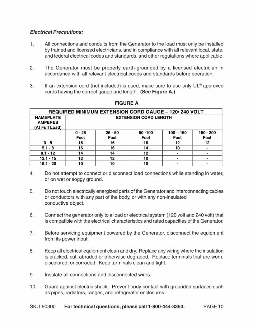
3. If an extension cord (not included) is used, make sure to use only UL® approvedcords having the correct gauge and length. (See Figure A.)
4. Do not attempt to connect or disconnect load connections while standing in water,or on wet or soggy ground.
5. Do not touch electrically energized parts of the Generator and interconnecting cablesor conductors with any part of the body, or with any non-insulatedconductive object.
6. Connect the generator only to a load or electrical system (120 volt and 240 volt) thatis compatible with the electrical characteristics and rated capacities of the Generator.
7. Before servicing equipment powered by the Generator, disconnect the equipmentfrom its power input.
8. Keep all electrical equipment clean and dry. Replace any wiring where the insulationis cracked, cut, abraded or otherwise degraded. Replace terminals that are worn,discolored, or corroded. Keep terminals clean and tight.
9. Insulate all connections and disconnected wires.
10. Guard against electric shock. Prevent body contact with grounded surfaces suchas pipes, radiators, ranges, and refrigerator enclosures.
SKU 90300 For technical questions, please call 1-800-444-3353. PAGE 11
INSTALLATION
1. NOTE: Prior to powering tools and equipment, make sure the Generator’s ratedvoltage, wattage, and amperage capacity (120V/ 20 AMPs and 240V/ 20 AMPs) isadequate to supply all electrical loads that the unit will power. If powering exceedsthe Generator’s capacity, it may be necessary to group one or more of the tools and/or equipment for connection to a separate Generator.
2. Electrical and other permits may be required for the installation of emergency powersystems. Investigate the local building and electrical codes before installing thisunit. Installation must be completed by licensed contractors.
3. WARNING! The Generator weighs 155 pounds. Use care and the proper liftingor hoisting equipment when moving it to the installation location. Always connecthoist lines to the Frame (21) of the Generator.
11. Use only Class BC or Class ABC fire extinguishers on electrical fires.
12. WARNING! People with pacemakers should consult their physician(s) beforeusing this product. Operation of electrical equipment in close proximity to a heartpacemaker could cause interference or failure of the pacemaker.
REV 03/06
SKU 90300 For technical questions, please call 1-800-444-3353. PAGE 12
GENERAL LOCATION
1. It is recommended to locate and install the Generator in a protected outdoor areawhere cooling air is readily available (see previous warning section).
2. Install the Generator so that the air inlets and outlets are not blocked by obstructionssuch as bushes, trees, or snow drifts. Locating it in the path of heavy winds orsnowdrifts may require the placement of a barrier for protection. The air inlet, innormal weather conditions, should face the prevailing wind direction.
3. Install the Generator on a concrete slab or other area where rain drainage or floodwaters can not reach it.
4. Generator placement should allow four feet of access to all sides for maintenance.
5. Place the Generator as close as possible to the electrical tools and equipmentbeing powered to reduce the length of extension cords.
6. If the Generator in located indoors, or in a Generator house, the Engine exhaustmust be ventilated to the outdoors using professionally installed, leakproof, heatresistant, flexible, metal tubing.
GENERATOR SUPPORT AND MOUNTING
1. Mount the Generator on a concrete slab capable of supporting the weight of theGenerator. The slab must extend on all sides beyond the Frame (21) by at leastone foot. Contact a cement contractor for slab specifications if necessary. Attachthe Frame to the concrete slab using 3/8” diameter masonry type anchor bolts (notsupplied).
GROUNDING THE GENERATOR
1. NOTE: It is recommended that only a trained and licensed electrician perform thisprocedure. (Generators without a permanent installation may not need to begrounded, check local codes and ordinances.)
2. Connect a #6 AWG grounding wire (not included) from the Grounding Point on thefront panel to a grounding rod (not included) that has been driven at least 24 inchesdeep into the earth. The grounding rod must be an earth-driven copper or brass rod(electrode) which can adequately ground the Generator.(See Figure H, page 15.)
Note: Local codes and ordinances may vary. Always check local codes and install inaccord with all laws.
REV 08/04; 11/04
SKU 90300 For technical questions, please call 1-800-444-3353. PAGE 13
OPERATING INSTRUCTIONS
NOTE: For additional references to the parts listed in the following pages, refer to theAssembly Diagram on page 19.
To Install A Battery:
1. NOTE: The Generator requires the installation of a 12 volt battery (not included).The battery must be no larger than 5” wide x 7-3/4” long x 8-1/2” high.
2. WARNING! Battery fluid leakage may occur under extreme usage or temperatureconditions. If battery fluid comes in contact with skin, wash with soap and water andrinse with lemon juice and vinegar. If the fluid comes into contact with the eyes,flush with water for several minutes and contact a doctor immediately. Never burn abattery, as it can explode in a fire. Do not use the Generator with a leaking battery.Contact local solid waste authorities for instructions on correct disposal or recyclingof a battery.
3. Carefully place a fully charged, 12 volt battery in the Battery Holder located at thebase of the Generator.
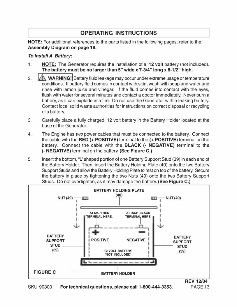
4. The Engine has two power cables that must be connected to the battery. Connectthe cable with the RED (+ POSITIVE) terminal to the (+ POSITIVE) terminal on thebattery. Connect the cable with the BLACK (- NEGATIVE) terminal to the(- NEGATIVE) terminal on the battery. (See Figure C.)
5. Insert the bottom, “L” shaped portion of one Battery Support Stud (39) in each end ofthe Battery Holder. Then, insert the Battery Holding Plate (40) onto the two BatterySupport Studs and allow the Battery Holding Plate to rest on top of the battery. Securethe battery in place by tightening the two Nuts (49) onto the two Battery SupportStuds. Do not overtighten, as it may damage the battery. (See Figure C.)
NUT (49) NUT (49)
BATTERYSUPPORT
STUD(39)
BATTERYSUPPORT
STUD(39)
BATTERY HOLDING PLATE(40)
BATTERY HOLDER
12 VOLT BATTERY(NOT INCLUDED)
POSITIVE NEGATIVE
ATTACH BLACKTERMINAL HERE.
ATTACH REDTERMINAL HERE.
FIGURE C
REV 12/04
SKU 90300 For technical questions, please call 1-800-444-3353. PAGE 14
Pre-Start Checks:
1. NOTE: During operation, it may be necessary to refer to the Engine manufacturer’sOperation, Maintenance, and Parts manual (included) for detailed information aboutstarting, running, and stopping the Engine.
2. Check to make sure the Engine’s “ON/OFF” Switch is in its “OFF” position.
3. Unscrew and remove the Engine’s Oil Fill Cap located at the bottom of the EngineCrankcase. Check to make sure the oil level is even with the top of the Oil Fill Hole.If necessary, add oil until its level is even with the Oil Fill Hole. Then, screw the OilFill Cap back into the Oil Fill Hole. NOTE: Check with the Engine manufacturer’smanual for the proper type of engine oil required for use.(See Figure D.)
4. Check the Fuel Gauge (34) for the amount of unleaded gasoline in the Fuel Tank(32). If necessary, remove the Fuel Tank Cap (37) and refill the Fuel Tank with un-leaded gasoline. Then, replace the Fuel Tank Cap.(See Figure E.)
FIGURE D
OIL FILL CAP
FUEL GAUGE (34)FUEL TANK CAP (37)
FUEL TANK (32)
FIGURE E
SKU 90300 For technical questions, please call 1-800-444-3353. PAGE 15
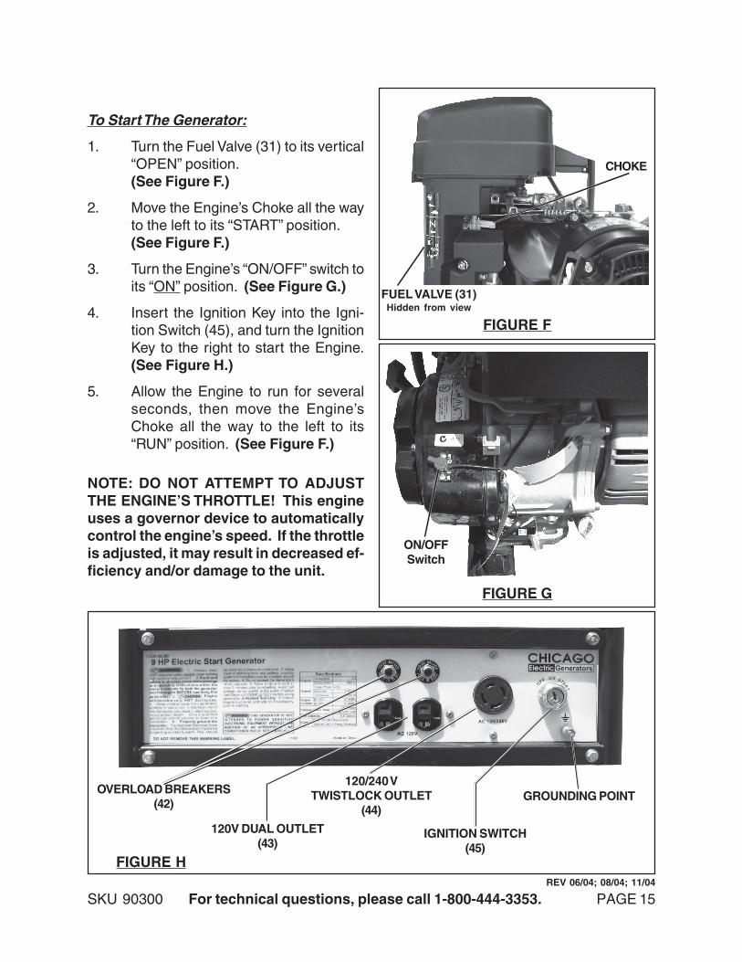
To Start The Generator:
1. Turn the Fuel Valve (31) to its vertical“OPEN” position.(See Figure F.)
2. Move the Engine’s Choke all the wayto the left to its “START” position.(See Figure F.)
3. Turn the Engine’s “ON/OFF” switch toits “ON” position. (See Figure G.)
4. Insert the Ignition Key into the Igni-tion Switch (45), and turn the IgnitionKey to the right to start the Engine.(See Figure H.)
5. Allow the Engine to run for severalseconds, then move the Engine’sChoke all the way to the left to its“RUN” position. (See Figure F.)
NOTE: DO NOT ATTEMPT TO ADJUSTTHE ENGINE’S THROTTLE! This engineuses a governor device to automaticallycontrol the engine’s speed. If the throttleis adjusted, it may result in decreased ef-ficiency and/or damage to the unit.
120V DUAL OUTLET(43)
OVERLOAD BREAKERS(42)
IGNITION SWITCH(45)
FIGURE H
120/240 VTWISTLOCK OUTLET
(44)GROUNDING POINT
FIGURE G
ON/OFFSwitch
FUEL VALVE (31)Hidden from view
CHOKE
FIGURE F
REV 06/04; 08/04; 11/04
SKU 90300 For technical questions, please call 1-800-444-3353. PAGE 16
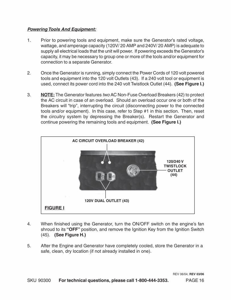
Powering Tools And Equipment:
1. Prior to powering tools and equipment, make sure the Generator’s rated voltage,wattage, and amperage capacity (120V/ 20 AMP and 240V/ 20 AMP) is adequate tosupply all electrical loads that the unit will power. If powering exceeds the Generator’scapacity, it may be necessary to group one or more of the tools and/or equipment forconnection to a separate Generator.
2. Once the Generator is running, simply connect the Power Cords of 120 volt poweredtools and equipment into the 120 volt Outlets (43). If a 240 volt tool or equipment isused, connect its power cord into the 240 volt Twistlock Outlet (44). (See Figure I.)
3. NOTE: The Generator features two AC Non-Fuse Overload Breakers (42) to protectthe AC circuit in case of an overload. Should an overload occur one or both of theBreakers will “trip”, interrupting the circuit (disconnecting power to the connectedtools and/or equipment). In this case, refer to Step #1 in this section. Then, resetthe circuitry system by depressing the Breaker(s). Restart the Generator andcontinue powering the remaining tools and equipment. (See Figure I.)
AC CIRCUIT OVERLOAD BREAKER (42)
120V DUAL OUTLET (43)
120/240 VTWISTLOCK
OUTLET(44)
FIGURE I
4. When finished using the Generator, turn the ON/OFF switch on the engine’s fanshroud to its “OFF” position, and remove the Ignition Key from the Ignition Switch(45). (See Figure H.)
5. After the Engine and Generator have completely cooled, store the Generator in asafe, clean, dry location (if not already installed in one).
REV 06/04; REV 03/06
SKU 90300 For technical questions, please call 1-800-444-3353. PAGE 17
INSPECTION, MAINTENANCE, AND CLEANING
1. NOTE: Preventative maintenance procedures and frequency will vary dependingon the amount of Generator use. Refer to the Engine manufacturer’s Operation,Maintenance, and Parts manual (included) for detailed information regardingmaintenance of the Engine.
2. CAUTION! Always turn off the Engine and remove the Ignition Key. Allowsufficient time for the Engine and Generator to completely cool. Then,disconnect the negative battery cable from the battery before performing anyinspection, maintenance, or cleaning.
3. BEFORE EACH USE, inspect the general condition of the Generator. Check forloose screws, misalignment or binding of moving parts, cracked or broken parts,damaged electrical wiring, and any other condition that may affect its safe operation.If abnormal noise or vibration occurs, have the problem corrected before furtheruse. Do not use damaged equipment.
4. BEFORE EACH USE, check to make sure the Engine’s oil level is adequate. Referto the Engine manufacturer’s Operation, Maintenance, and Parts Manual (included)for specific information.
5. DAILY: With a soft brush, cloth, or vacuum, remove all debris from the Generator.Then, use a premium quality, lightweight machine oil to lubricate all moving parts.
PLEASE READ THE FOLLOWING CAREFULLY
THE MANUFACTURER AND/OR DISTRIBUTOR HAS PROVIDED THE PARTS LIST AND ASSEMBLYDIAGRAM IN THIS MANUAL AS A REFERENCE TOOL ONLY. NEITHER THE MANUFACTURER ORDISTRIBUTOR MAKES ANY REPRESENTATION OR WARRANTY OF ANY KIND TO THE BUYER THAT HEOR SHE IS QUALIFIED TO MAKE ANY REPAIRS TO THE PRODUCT, OR THAT HE OR SHE IS QUALIFIEDTO REPLACE ANY PARTS OF THE PRODUCT. IN FACT, THE MANUFACTURER AND/OR DISTRIBUTOREXPRESSLY STATES THAT ALL REPAIRS AND PARTS REPLACEMENTS SHOULD BE UNDERTAKEN BYCERTIFIED AND LICENSED TECHNICIANS, AND NOT BY THE BUYER. THE BUYER ASSUMES ALLRISK AND LIABILITY ARISING OUT OF HIS OR HER REPAIRS TO THE ORIGINAL PRODUCT ORREPLACEMENT PARTS THERETO, OR ARISING OUT OF HIS OR HER INSTALLATION OF REPLACEMENTPARTS THERETO.
SKU 90300 For technical questions, please call 1-800-444-3353. PAGE 18
REV 06/04; 12/04; 01/05; REV 03/06
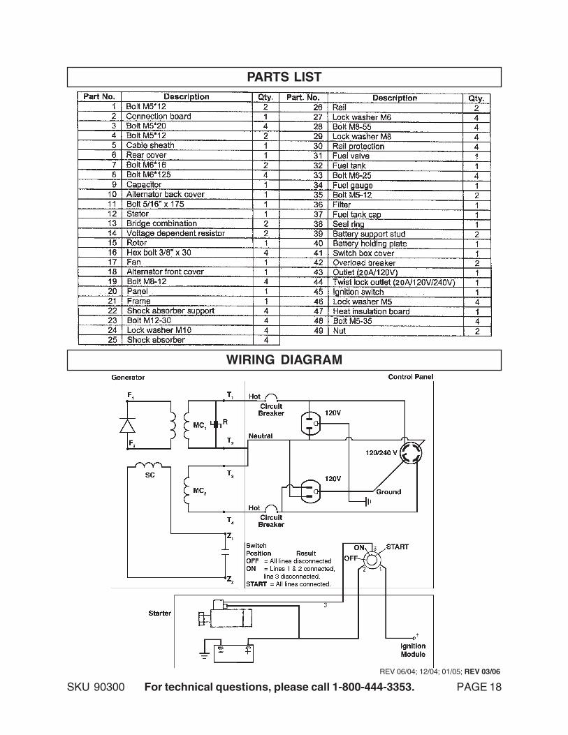
PARTS LIST
WIRING DIAGRAM
2020
SKU 90300 For technical questions, please call 1-800-444-3353. PAGE 19
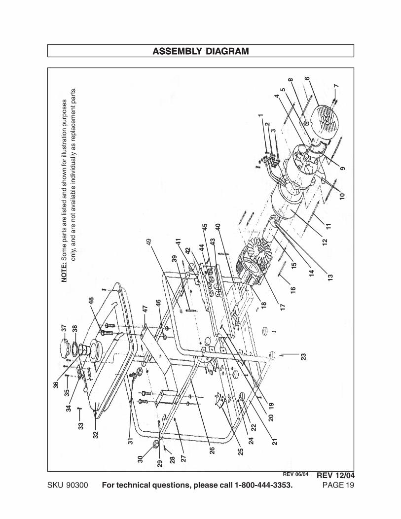
ASSEMBLY DIAGRAM
33
32
31
30
29 28 27
26 25
2422
2120
19
23
18 17
1615
14
1312
11
109
7
6
5
8
43
21
4043
454442
4139
46
47
48
383736
3534
NO
TE
: Som
e pa
rts
are
liste
d an
d sh
own
for i
llust
ratio
n pu
rpos
es
on
ly, a
nd a
re n
ot a
vaila
ble
indi
vidu
ally
as
repl
acem
ent p
arts
.
ASSEMBLY DIAGRAM
REV 06/04
49
REV 12/04
SKU 90300 For technical questions, please call 1-800-444-3353. PAGE 20
1 YEARWARRANTY
Harbor Freight Tools Co. makes every effort to assure that its products meet high quality and durability standards,and warrants to the original purchaser that this product is free from defects in materials and workmanship forthe period of one year from the date of purchase (90 days if used by a professional contractor or if used asrental equipment). See engine manufacturer’s warranty which covers engine. This warranty does not apply todamage due directly or indirectly, to misuse, abuse, negligence or accidents, repairs or alterations outside ourfacilities, or to lack of maintenance. We shall in no event be liable for death, injuries to persons or property, orfor incidental, contingent, special or consequential damages arising from the use of our product. Some statesdo not allow the exclusion or limitation of incidental or consequential damages, so the above limitation ofexclusion may not apply to you. THIS WARRANTY IS EXPRESSLY IN LIEU OF ALL OTHER WARRANTIES,EXPRESS OR IMPLIED, INCLUDING THE WARRANTIES OF MERCHANTABILITY AND FITNESS.
To take advantage of this warranty, the product or part must be returned to us with transportation chargesprepaid. Proof of purchase date and an explanation of the complaint must accompany the merchandise. If ourinspection verifies the defect, we will either repair or replace the product at our election or we may elect torefund the purchase price if we cannot readily and quickly provide you with a replacement. We will returnrepaired products at our expense, but if we determine there is no defect, or that the defect resulted fromcauses not within the scope of our warranty, then you must bear the cost of returning the product.
This warranty gives you specific legal rights and you may also have other rights which vary from state to state.
3491 Mission Oaks Blvd. • PO Box 6009 • Camarillo, CA 93011 • (800) 444-33533491 Mission Oaks Blvd. • PO Box 6009 • Camarillo, CA 93011 • (800) 444-33533491 Mission Oaks Blvd. • PO Box 6009 • Camarillo, CA 93011 • (800) 444-33533491 Mission Oaks Blvd. • PO Box 6009 • Camarillo, CA 93011 • (800) 444-33533491 Mission Oaks Blvd. • PO Box 6009 • Camarillo, CA 93011 • (800) 444-3353


![Final rule: Facilitating Capital Formation and Expanding ... · 17 CFR Parts 227, 229, 230, 239, 240, 249, 270, and 274 [Release Nos. 33-10884; 34-90300; IC-34082; File No. S7-05-20]](https://static.documents.pub/doc/80x56/60ce98acea74ee55bd2a8b80/final-rule-facilitating-capital-formation-and-expanding-17-cfr-parts-227-229.jpg)


