Version 1/07 KDOT Bridge Section 9.0 - Structure Steel - i
Kansas Department of Transportation Bridge Construction Manual
Disclaimer: This website and documents are provided for use by persons outside of the Kansas Department of Transportation as
information only. The Kansas Department of Transportation, the State of Kansas, nor its officers or employees, by making this
website and documents available for use by persons outside of KDOT, does not undertake any duties or responsibilities of any such
person or entity who chooses to use this website and documents. This website and documents should not be substituted for the
exercise of a person�s own professional judgment nor the determination by contractors of the appropriate manner and method of
construction on projects under their control. It is the user�s obligation to make sure that he/she uses the appropriate practices. Any
person using this website and documents agrees that KDOT will not be liable for any commercial loss; inconvenience; loss of use,
time, data, goodwill, revenues, profits, or savings; or any other special, incidental, indirect, or consequential damages in any way
related to or arising from use of this website and documents.
.
Version 1/07 KDOT Bridge Section 9.0 -Structure Steel - ii
Kansas Department of Transportation Bridge Construction Manual
9.0 STRUCTURAL STEEL
9.1 GeneralStructural Steel girders/beams are used on many KDOT bridge projects where geometry or span lengths limit the use of other materials. Steel is both strong and flexible, which makes it ideally suited for bridge construction. For modern bridges, the member types are usually limited to rolled beams, plate girders and steel box girders. Rolled beams are shapes produced at the steel mill from solid stock and cut to length to fit the project. The shapes commonly used by bridge design-ers are called W-Sections, which look like an "I". The top and bottom of the "I" are the flanges and the middle section is the web. The depth of the beam usually varies from 24" to 40" and usu-ally the web is in proportion with the flange section. Plate girders are fabricated from plate stock cut to length with the webs and flanges welded together. The web depths usually vary from 48" to 120" with the webs being very thin in proportion to the height of the section. Box girder sections are fabricated in a fashion similar to a plate girder except that there are two webs that form the sides of the box. The box girder has either a trapezoidal or a rectangular cross-section.
Plate girder and attachments
Steel girders have vertical plates welded to the webs called stiffeners. Stiffeners do just as their name implies, they stiffen the web. These plates are attached in the shop in a plumb position. Stiffeners may be perpendicular to or at an angle to the web centerline, depending upon the bridge skew. There are three types of vertical stiffeners: connection stiffeners, intermediate stiffeners and bearing stiffeners. Connection stiffeners provide a method of attaching cross-frames or dia-phragms between adjacent members to add stability to the bridge during construction. These stiffeners have bolt holes that match the cross-frame or diaphragm bolt holes for each position on
Version 1/07 KDOT Bridge Section 9.0 -Structural Steel- 1
Kansas Department of Transportation Bridge Construction Manual
the bridge. Connection stiffeners are required to be attached to both flanges, this attachment is usually a shop weld. In some cases shop bolting is used on the tension flange, but this is less fre-quent. Intermediate stiffeners do not need to be attached to either top or bottom flange. Bearing stiffeners are much like connection stiffeners in that they are welded to both top and bottom flanges and the web. They must be installed in multiples of two, one on each side of the web. It is not uncommon to find four or even six stiffeners at a bearing location. Bearing stiffeners are usu-ally much thicker than intermediate or connection stiffeners because they pass all of the vertical loads from the deck and superstructure to the bearing devices. The plans will show grind to bear for the bottom flange and tight fit for the top which are exacting fit requirements. Bearing stiffen-ers also act as connection plates for end diaphragms or cross frames. These frames will be heavier and have different bolt hole spacing than interior frames. Care should be taken so that there is not a mix up between the two types of frames. Cross-frames or diaphragms are considered secondary members for tangent or straight bridges. They are considered to be primary members when used in curved bridges. Secondary members may have oversized or slotted holes to aid in the erection and fit-up of the structure.
The bearing stiffener locates the centerline of bearing and is a critical control line of the structure. The centerline of the abutments or piers may or may not be the same as the centerline of bearing, as in the case of a unit change on a common pier. It is important to insure that the centerline of bearing of the girder is located over the centerline of bearing of the pier or abutment.
Beams and girder shapes are fabricated out of either weathering steel or plain carbon steel. The plain carbon steel structures are painted while weathering steel girders may be painted in whole or partially. The field surface finishes will vary for these two types of materials. The plan notes will guide the Contractor as to the final product expectations; see the painting section of the Bridge Construction Manual for details.
A structural steel erection base sheet is included with all plans for structural steel bridges. A .pdf of that base sheet may be accessed through the following link, Steel Erection Base Sheet.
9.2 Contract and Specification:The specifications require that the Contractor provide written notification of the name and the location of the steel fabricator to the State Bridge Engineer and the Chief of the Bureau of Materi-als and Research within ten days after the contract is signed. Prior to the fabrication of any struc-tural steel or castings, the Contractor or Fabricator is required to submit shop drawings to the Engineer for approval. Any work done prior to this will be at the Contractors risk. The Contrac-tor will give enough advanced notice to the Engineer prior to the beginning of the fabrication work so inspection can be provided.
9.3 Shop Drawings:Shop drawings are required for all steel structures governed under Section 705.5b of the Standard Specifications. The shop drawings should contain the following information: Typical layouts, camber diagrams, erection and framing plans, bolt information and girder details. Review this information to become familiar with the way the structural steel is to be assembled. An important
Version 1/07 KDOT Bridge Section 9.0- Structural Steel - 2
Kansas Department of Transportation Bridge Construction Manual
part of the shop drawings is matchmarking. Check matchmarks on members and assemblies to ensure that they are arranged, assembled, and erected based on the Fabricator's matchmarking diagram.
9.3.1 Typical LayoutsTypical layouts are used to coordinate the geometry of connections that appear throughout the structure. Field splices are not generally shown on these sheets. These sheets will usually show cross frame geometry, connection plate dimensions, girder spacing, and web depths.
9.3.2 Camber Note: These drawings may illustrate webs and flanges or just webs.Camber sheets, sometimes called web cutting details, show camber ordinates at equal spaces, or spaces per Fabricator request, relative to a baseline. The baseline should pass through the end points of the web plate at the bottom, unless the web plate is haunched or tapered, then the base-line might pass through the top end points. On web camber diagrams with an end overhang or simple span web cambers, the baseline should pass through the centerline of bearing(s). These sheets will show end overhangs and centerlines of bearing (if applicable). Top and bottom dimen-sions and end cuts relative to the baseline are shown on these sheets. Web plate thickness, width, lengths and marks are also shown on these sheets.
The width of the plate is usually billed as nominal width. A camber cutting allowance is to be added to the width when material is ordered. Some Fabricators might bill the ordered size in lieu of the nominal. The web material will be called out on these sheets as well as plates which are to be Charpy V-Notch tested.
9.3.3 Erection Framing Plan The framing or erection plan will show the location of all the items provided by the Fabricator. Horizontal span lengths and girder spacing along the bearings are shown on these sheets. The framing plan will show the shipping marks in the same relative position as it will be when the steel is erected. Field welded items, if any, will be located and weld symbols will also be shown on these sheets.
Each field connection should be described so the erector can correctly locate it. On complicated connections with multiple plies and pieces, special sketches may be shown. A schematic is some-times shown on the blocking diagram, with a detail shown on the girder details sheet. The thick-ness of each plate to be fastened, material details and requirements for V-notch testing will also be shown here. The field bolt summary will show the material specification for each fastener assembly (bolt, nut, washer, shear stud, etc.), along with the actual count for each bolt length/diameter.
9.3.4 Girder DetailsThe girder details will provide an elevation view of the girder web and plan view of the flanges. Generally the girders are broken down into pieces between field splices. All stiffeners and con-
Version 1/07 KDOT Bridge Section 9.0 -Structural Steel- 3
Kansas Department of Transportation Bridge Construction Manual
nection plates will be shown here. The bolt hole pattern for the field splices will also be shown on these sheets. All of the weld procedures for the section of girder being detailed and plate marks will be shown here.
9.4 Shipping, Handling and Storage: It is very important to check for damaged girders as the pieces arrive on the project site. Shop inspection occurs during fabrication, however, it is impossible to monitor the bridge pieces in route to the site or in the shop after the KDOT shop inspector has approved the pieces. One cause of damage to the girders is improper chaining of the load. ‘Softeners’ are devices designed to pro-tect the flanges from damage caused by chains used to secure the girder during transport. If ‘soft-eners’ have not been used, look for flange damage. Pay particular attention to bearing device locations. The finished mating surfaces of bearings can be easily damaged if used as a hold down point for chaining the load, or as a lifting point for off-loading. The contractor should store bridge members in an upright and level position; i.e. on blocks to keep them out of the mud. The Con-tractor will provide the bridge members, in transport and storage, with the proper support so that excessive deflection does not occur. Improper handling can result in geometric changes in the beam or girder making them difficult to construct. Plate girders will have to be chained, shored, or cribbed in the storage area so that accidental overturning does not occur. Rolled beams are inherently more stable and less likely to turnover; however, placing them on uneven supports in not advised. The order in which the pieces are stored will usually match the sequence in which they are to be erected. Look for damage on each piece in the field before it is installed in the bridge.
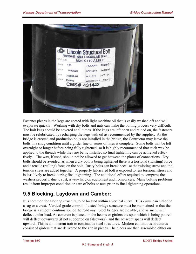
Fasteners and hardware are packaged in sealed metal kegs to prevent damage from moisture and debris. The kegs have lot numbers on them that identify the materials assigned to each project or site. Each lot of bolts, nuts, washers and DTI's will be tested and the results available in CMS reported as approved for use.
Version 1/07 KDOT Bridge Section 9.0- Structural Steel - 4
Kansas Department of Transportation Bridge Construction Manual
Fastener pieces in the kegs are coated with light machine oil that is easily washed off and will evaporate quickly. Working with dry bolts and nuts can make the bolting process very difficult. The bolt kegs should be covered at all times. If the kegs are left open and rained on, the fasteners must be relubricated by recharging the kegs with oil as recommended by the supplier. As the bridge is erected and production bolts are installed in the bridge, the Contractor may leave the bolts in a snug condition until a girder line or series of lines is complete. Some bolts will be left overnight or longer before being fully tightened, so it is highly recommended that stick wax be applied to the threads while they are being installed so final tightening can be achieved effec-tively. The wax, if used, should not be allowed to get between the plates of connections. Dry bolts should be avoided, as when a dry bolt is being tightened there is a torsional (twisting) force and a tensile (pulling) force on the bolt. Rusty bolts can break because the twisting stress and the tension stress are added together. A properly lubricated bolt is exposed to less torsional stress and is less likely to break during final tightening. The additional effort required to compress the washers properly, due to rust, is very hard on equipment and ironworkers. Many bolting problems result from improper condition or care of bolts or nuts prior to final tightening operations.
9.5 Blocking, Laydown and Camber: It is common for a bridge structure to be located within a vertical curve. This curve can either be a sag or a crest. Vertical grade control of a steel bridge structure must be maintained so that the bridge is a smooth continuation of the roadway. Steel bridges are flexible, and as such, will deflect under load. As concrete is placed on the beams or girders the span which is being poured will deflect downward (if not supported on falsework), and the adjacent spans will deflect upward. This is an inherent trait to continuous steel structures. Modern continuous structures consist of girders that are delivered to the site in pieces. The pieces are then assembled either on
Version 1/07 KDOT Bridge Section 9.0 -Structural Steel- 5
Kansas Department of Transportation Bridge Construction Manual
the ground and lifted in place, or in their final positions. The result of this is a girder that has both the appearance and the structural integrity of being made of one piece from abutment to abutment, or expansion device to expansion device.
Steel structures are fabricated in the shop according to the dimensions on the shop drawings. These drawings include overall geometric control and individual piece cuts. The geometric con-trols are used by the shop to fabricate the pieces which will include the effects of vertical curva-ture and deflection. Fabricators use the laydown ordinates to layout the beams or girders, with the webs in a horizontal position, then splices can be located within the beams on the proper grade. Usually this is from a reference point at the lowest elevation done from a level line drawn on the shop floor. This puts the structure in a no load condition. When the structure is erected the dead load forces of the beams or girders act on the structure as if it were one beam after the field con-nections are finished.
A steel bridge located on any grade other than 0.00% will have relative elevation differences between the piers and abutments. This relative difference is reflected in the blocking diagram. If the bridge is to be erected on the ground, the blocking diagram will be used to bring the structure into a no load condition consistent with the fabrication orientation. The 'blocks' for the blocking will have to be surveyed to get the relative elevations for each piece at the bolted splice locations. The 'blocked' pieces must be stable and on unsettling material. The Contractor may elect to place compacted aggregate down and then set heavy timbers on top of that to 'block' or 'crib' the pieces. This keeps the pieces out of the mud, is easy to level and provides a firm base. The Contractor may choose to use two cranes to 'float' the pieces together. If this is the case, blocking is not nec-essary. No matter which method is used, the contractor must use drift pins to align the girder members.
Blocking Diagram is from Level Line in a 'no load' condition.
Rolled beams have natural camber that is a result of uneven cooling effects during the rolling pro-cess. Natural camber should always be orientated such that over the piers the beam is cambered down (the beam is smiling) and in midspan camber is up (the beam is frowning). Plate girder members have camber cut into the web called "fabricated camber". "Fabricated camber" is the vertical curvature built into a member to counteract the effects of the self weight of the structure and the vertical curvature of the roadway. That is, when the member has the full dead load applied (girder self weight, concrete, bridge rail and wearing surface) it will deflect and align itself with the theoretical profile or plan grade for that section of roadway.
Version 1/07 KDOT Bridge Section 9.0- Structural Steel - 6
Kansas Department of Transportation Bridge Construction Manual
9.6 Erection:The Contractor will provide:
• a detailed plan for the erection of the structure (not for simple structures).• shop details.• camber diagrams.• a list of field bolts (lot numbers and certifications).• a copy of the shipping statement showing a list of parts and their mass.
The Standard Specification states: “The Contractor shall furnish detail Plans for the erection of the structure”. These plans include the shop details; however, the shop details are not enough to qualify as “detail Plans for the erection of the structure.” Shop details specify how the fabricator will manufacture the beams for a particular project. These details include information about weld dimensions, plates sizes, stiffener and splice locations, and bolt hole details. Detailed erection plans must show the weights and lengths of the beams, centers of gravity, the equipment that will be used, and a sequence of how the girders will make it from storage on the site to their final posi-tions on the substructure. The sequence will show pick points, which girder lines will be erected first, and how the girders will be stabilized before they have all been erected and bolted. This is a minimum of the information that should be provided for straight-forward projects. Include more details on projects with a complex structure or complex erection techniques.
If falsework is required for erection of the steel, then falsework plans will be submitted as shown in KDOT’s Construction Specifactions and current Special Provisions which can be found in 708.
9.6.1 AssemblyThere are three steps to structural steel erection: assembly, fit-up, and bolting. Assembly is the process of maneuvering the pieces, with cranes, into their final positions in the structure. Fit-up is the proper alignment of the members and plates that make up the bolted connections. Finally, bolting is the operation to achieve proper design clamping forces. In the field, the lines of separa-tion for these steps may not be as clear cut. However, each step is considered a separate function that requires the Contractor to use special tools, skills and experience.
Successful erection of structural steel relies on proper substructure construction. Many of the problems experienced with structural steel erection are the results of poor substructure vertical and horizontal control. The Contractor must verify the bridge bearing seat elevations at abutment and pier locations before steel erection begins. If adjustments are required, they can be done much more effectively before erection begins. The Contractor should set or check the final grade at each bearing seat or step as the final lifts of concrete, filling the forms, reach that elevation. This will assure minimal delays and repair costs for the Contractor. The best procedure for final grading of the bearing seats is to shoot the elevations and nail on the chamfer strips after the forms are nearly full. This removes any error due to crush of the falsework. If there were any question in the elevations, the lesser of the two evils would be to have the bearing seat a bit high. It is bet-ter to grind down a bearing seat than to shim up the bearing. Finally, bearing seat elevations are to be "plane surfaces," meaning that they must be level in both directions. This will allow the bear-
Version 1/07 KDOT Bridge Section 9.0 -Structural Steel- 7
Kansas Department of Transportation Bridge Construction Manual
ing devices to work properly for the life of the bridge. A steel trowel is to be used on these sur-faces to make them smooth. It is important that the surface is not overworked. Excessive bleed water is evidence of overworked concrete. This condition produces a top layer of finished con-crete that is much weaker and less durable than intended. If the Contractor Construction Staking misses a beam seat elevation on the low side instead of the high side and it is out of tolerance then thin shims may have to be used. The disadvantage to using shims is that it is difficult to seal the shims from water. Thus, rust forms around the bearing.
Typically, during the assembly phase, there is a "ground crew" that selects the correct pieces based on match marks, shop drawings, and erection plans. This crew guides the cranes, coordi-nates any additional rigging (such as safety cables and tag lines), and hooks up the pieces to be hoisted. It is important that the piece marks on the shop or erection plan agree with the pieces being placed to form the structure. The connecting crew or "top men" guide the pieces and secure them to the structure in the proper alignment. As such, careful coordination between the crews is essential. The Contractor may elect to assemble parts of or an entire girder line on the ground. For this case the girders will be blocked to the proper relative elevation to match the piers and abutment relative elevations using the blocking diagram. Falsework bents may also be used in some cases to support the girders. A Contractor with more than one crane may elect to simply suspend two girder segments from cranes, (or "hold in-the-fall"), and float them together.
The stability of the structure during erection is of critical importance. The Contractor is required by Section 712.3 of the Standard Specification and latest revisions of the Special Provisions07-07004 to supply an erection plan. If the stability is in question, the Contractor's erection plan should be reviewed. A good rule of thumb for stability on a tangent bridge structure is that the ratio of the length of the girder to the width of the top flange should be less than 85. Ratios greater than that can become unstable if not braced. Initially the Contractor will have to get one piece in place over two supports and hold it there until the next adjacent pieces with frames can be con-nected.
9.6.2 Fit-UpFit-up is the process of aligning the members and the plies by using drift pins, supplemented with erection pins, erection bolts or "fit up" (non-production) bolts to properly align the girder seg-ments. Drift pins are steel pins that are tapered on both ends and cylindrical in the middle. The cylindrical portion has the same nominal diameter as the open hole. These pins are driven into the splice through all the plies at the corners of the web plates to align the pieces vertically. The flanges are drifted into correct horizontal alignment by driving drift pins into the corners of the plates. One quarter of the remaining holes for each plate will have drift pins installed in a uniform pattern. For proper alignment only light drifting is allowed; heavy drifting, which would deform the bolt holes, is not allowed. Initallly, align the members vertically by light drifting of the cor-ners of the web plates. Next, align the members horizontally by light drifting of the corners of the flange plates.
Cross-Frames and diaphragms should be pinned and bolted to a snug condition and not fully tight-ened until all of the girder lines are completed. This will provide stability but allow adjustment. If all of the tolerances and adjustments are "used up" in the first couple of bays, great difficulties can develop in the rest of the girder lines.
Version 1/07 KDOT Bridge Section 9.0- Structural Steel - 8
Kansas Department of Transportation Bridge Construction Manual
9.6.3 BoltingBridge girder lines are made up of many pieces that are bolted together in the field. These bolted connections must be properly aligned and tightened before the splice can perform as designed. Field splices are generally located near a point of zero dead load bending stress. The field splices are labeled on the erection sheets of the Shop Drawings and may differ from those shown on the Plans.
A bolted field splice is fabricated in the shop by setting the members to the proper elevation according to the blocking diagram. The plies of the splice are sub drilled at the corner locations and bolted through all the plies. The remaining holes are drilled or punched from the solid (all plies at the same time). Then, depending on the type of structural geometry that exists in the bridge, the shop erects the pieces according to the assembly method (Type A, B, or C) as noted on the Plans or as specified in subsection 712 of the Standard Specifications. For horizontally curved structures, all girder lines for the full bridge width are shop assembled, including diaphragms or cross-frames, to the final required shape. Field erection of a steel bridge is the reassembling of the fabricated pieces following the match marking from the Shop Drawings, and using proper erection and fit-up procedures. In both cases, the structure's blocking or lay down ordinates are used to obtain proper relative relationships.
A bolted field splice is designed as a slip critical connection. This type of connection relies on the clamping force provided by the bolts in tension and the friction between the plies. It is critical that splice plates, and beam or girder ends, are kept free from debris and oil which would change the friction coefficient between the plies. The previous splice conditions are applicable in addition to removing mill scale and any loose rust that is easily removed by mechanical methods on weather-ing steel. The correct tension in the bolts is achieved by proper bolting techniques and measured by specialized load cell washers called direct tension indicators (DTIs) which compress at a given bolt tension force.
The production bolts installed in beam flange splices should be orientated heads up to allow a failed bolt to become engaged in bearing rather than falling out due to gravity thus leaving a vacant bolt hole. In external beams the production bolts placed in web splices should be orientated with the head on the outward face of the beam web. For internal beams bolt head orientation should remain the same in a single splice and for all splices along a beam line. According to con-struction specifications section 700 surface preparations for priming of all surfaces includes blast-ing with abrasives. This includes all nonweathering fasteners. Weathering fasteners located in areas where painting is specified in contract documents are also to be blasted.
Fit-up bolts are used to bring all of the plies in each splice into firm contact. It is best not to use production bolts with DTIs for fit-up bolting, because the DTIs may be damaged. These fit-up bolts can be of a different grade and size from the production bolts. As a minimum these bolts will be 7/8" diameter and meet ASTM A325 for primary members and 3/4" bolts for secondary members. These are easy to obtain by the Contractor and can be reused many times. It is impor-tant to clearly mark erection bolts so that they are not left in the structure. This can be done by grinding the bolt identification marks off of the bolt heads, or painting the bolts and nuts.
Version 1/07 KDOT Bridge Section 9.0 -Structural Steel- 9
Kansas Department of Transportation Bridge Construction Manual
Drifting Girders
As mentioned above erection bolts are used to draw the plates together and force all the plies into contact. They also provide some of the necessary clamping force so the plies don't slip during erection and bolting. Using fit-up bolts to bring all of the plies together helps to achieve a uni-form snug condition. This in turn leads to a uniform turn of the nut. Except for the corners of the plates, which should be pinned first, the splices should be 'ironed out' from the center toward the edges. This 'ironing' of the plates or plies can be thought of as applying a sticker to a window. Application is started at the center and then it is flattened toward the edges to get the air out and make it lay flat against the window.
Make sure the Contractor is using the proper fastener at the proper location. The shop drawings will spell out what fasteners go where. Do not allow the Contractor to mix and match galvanized fasteners with black fasteners.
Final Bolting (Note: Drift Pins are still in place. )
Version 1/07 KDOT Bridge Section 9.0- Structural Steel - 10
Kansas Department of Transportation Bridge Construction Manual
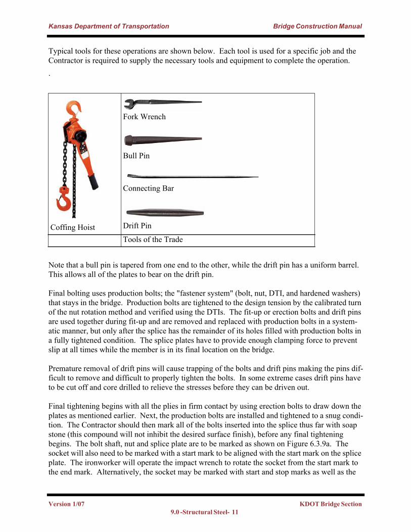
Typical tools for these operations are shown below. Each tool is used for a specific job and the Contractor is required to supply the necessary tools and equipment to complete the operation..
Note that a bull pin is tapered from one end to the other, while the drift pin has a uniform barrel. This allows all of the plates to bear on the drift pin.
Final bolting uses production bolts; the "fastener system" (bolt, nut, DTI, and hardened washers) that stays in the bridge. Production bolts are tightened to the design tension by the calibrated turn of the nut rotation method and verified using the DTIs. The fit-up or erection bolts and drift pins are used together during fit-up and are removed and replaced with production bolts in a system-atic manner, but only after the splice has the remainder of its holes filled with production bolts in a fully tightened condition. The splice plates have to provide enough clamping force to prevent slip at all times while the member is in its final location on the bridge.
Premature removal of drift pins will cause trapping of the bolts and drift pins making the pins dif-ficult to remove and difficult to properly tighten the bolts. In some extreme cases drift pins have to be cut off and core drilled to relieve the stresses before they can be driven out.
Final tightening begins with all the plies in firm contact by using erection bolts to draw down the plates as mentioned earlier. Next, the production bolts are installed and tightened to a snug condi-tion. The Contractor should then mark all of the bolts inserted into the splice thus far with soap stone (this compound will not inhibit the desired surface finish), before any final tightening begins. The bolt shaft, nut and splice plate are to be marked as shown on Figure 6.3.9a. The socket will also need to be marked with a start mark to be aligned with the start mark on the splice plate. The ironworker will operate the impact wrench to rotate the socket from the start mark to the end mark. Alternatively, the socket may be marked with start and stop marks as well as the
Coffing Hoist
Fork Wrench
Bull Pin
Connecting Bar
Drift Pin
Tools of the Trade
Version 1/07 KDOT Bridge Section 9.0 -Structural Steel- 11
Kansas Department of Transportation Bridge Construction Manual
splice plate. The final tightening should take 10 seconds or less. If it takes longer, something could be wrong with the equipment or the bolt. The inspector will verify this rotation and the number of DTI refusals with the appropriate feeler gage.
Figure: 6.3.9a
Finished Splice (Note: Turn Marks)
Version 1/07 KDOT Bridge Section 9.0- Structural Steel - 12
Kansas Department of Transportation Bridge Construction Manual
Typical causes for bolting problems
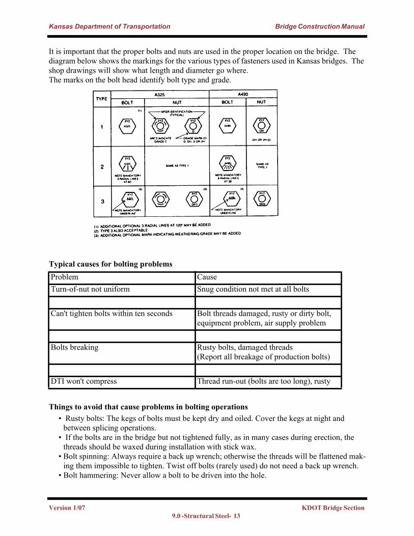
It is important that the proper bolts and nuts are used in the proper location on the bridge. The diagram below shows the markings for the various types of fasteners used in Kansas bridges. The shop drawings will show what length and diameter go where. The marks on the bolt head identify bolt type and grade.
Things to avoid that cause problems in bolting operations• Rusty bolts: The kegs of bolts must be kept dry and oiled. Cover the kegs at night and
between splicing operations.• If the bolts are in the bridge but not tightened fully, as in many cases during erection, the
threads should be waxed during installation with stick wax.• Bolt spinning: Always require a back up wrench; otherwise the threads will be flattened mak-
ing them impossible to tighten. Twist off bolts (rarely used) do not need a back up wrench.• Bolt hammering: Never allow a bolt to be driven into the hole.
Problem CauseTurn-of-nut not uniform Snug condition not met at all bolts
Can't tighten bolts within ten seconds Bolt threads damaged, rusty or dirty bolt, equipment problem, air supply problem
Bolts breaking Rusty bolts, damaged threads (Report all breakage of production bolts)
DTI won't compress Thread run-out (bolts are too long), rusty
Version 1/07 KDOT Bridge Section 9.0 -Structural Steel- 13
Kansas Department of Transportation Bridge Construction Manual
• Bolt trapping: Premature removal of drift pins will cause plies to shift and damage threads.
Initially, as a splice is made up, there may be significant gaps between the plies of the splice. If this is the case, using erection bolts will be necessary to bring the plates into contact before pro-duction bolts are snugged. Using production bolts to do this may damage the production bolts and/or the DTIs. Drifting should always be accomplished first, followed by the use of erection bolts, which bring the plies into contact and secure the splice. In the initial assembly, the Contrac-tor should not align the members using production bolts. This could result in the removal and replacement of damaged production bolts, requiring the realignment of members, which increases cost with unnecessary labor and wasted materials. After the members are aligned with drift pins and erection bolts, the remaining holes are filled, snugged, and fully tightened with production bolts. Once this has been completed, the erection bolts and drift pins are replaced with properly tightened production bolts.
The following standard sheet was developed to help the inspector monitor the erection of struc-tural steel. The sheet is a summary of the requirements in the previous sections, and it illustrates the minimum standard that the contractor must follow in order to bolt structural steel splices. This is a standard sheet, and does not fulfill the standard specification requirement for a detailed field erection plan. Each project will have details that will need to be considered beyond what is shown on this standard.
Version 1/07 KDOT Bridge Section 9.0- Structural Steel - 14
Kansas Department of Transportation Bridge Construction Manual
Bridge Standard (BR 210)
Version 1/07 KDOT Bridge Section 9.0 -Structural Steel- 15
Kansas Department of Transportation Bridge Construction Manual
9.6.4 Calibration and Inspection:Section 712 of the Standard Specifications and Special Provision 90M-65 fully covers this item, however a few additional words here may help. First, turn-of-the-nut bolt tightening is the required procedure in Kansas. Torque methods are not used to tighten bolts in Kansas bridges. Torque has a variable relationship with tension; bolt torque and the tension in the bolt shaft cannot be related directly.
KDOT has adopted the calibrated turn-of-the-nut tightening method, which gives a target rotation from a snug condition. This calibration of the turn is required for each bolt length and diameter. Once this target is known, and if proper erection and fit-up is followed, the bolting operation should be very efficient. The inspector does not have to witness the tightening of every bolt. The procedure and patterns of tightening and fit-up insure compliance is established on the first splice or two. Inspection will follow the bolting operation using feeler gages. The Contractor could be delayed if the inspector is hovering over him at every bolt location. Proper inspection of a bolted field splice includes visually comparing the overall pattern of the threads sticking out past the nut. This should be uniform and will verify that the correct bolt length has been used for all the bolts in the splice. Everyday 100% of the first splice should be checked using the feeler gages; after that, every other bolt is a good rule of thumb unless poor results are found. However, each bolt will have to be checked visually to verify that the proper turn has been made. Under no condition should any bolt be left under tightened. Basically, the bolt is acceptable if half or more of the gaps reject the 0.005 inch feeler gage and the nut has not been turned more that 45º degrees beyond the calibrated turn. See the Steel Erection, Fit-up and Bolting Procedure sheet in the plans.
9.7 Misfits: A misfit is the condition that exists when the Contractor is not able to get the pieces of the girder lines to bolt together using reasonable methods that do not bend or distort the members being con-nected. There are two categories: misfits in primary members, and secondary members. Exam-ples of a primary member are the main longitudinal girder, or a cross-frame or diaphragm on a horizontally curved bridge. An example of a secondary member is a cross-frame or diaphragm on a bridge that is on tangent (straight bridge) or with only mild curvature. The Contractor is NOT to ream a primary bridge member without first contacting the State Bridge Office.
Typical causes for misfits on primary members: • Incorrect grade at bearing seat elevations.• Bolt holes which have been improperly drilled (see the photo below).• Finish on bearing seat not level, leading to webs not being plumb.• Improper fit-up of members (splices not drifted into position).• Incorrect bearing device, or incorrect orientation of device.• Bent or distorted members from shipping, lifting, or forcing members into position. • Wrong pieces being connected-check matchmarks on Shop Drawings.• Members shifted by the wind.
Version 1/07 KDOT Bridge Section 9.0- Structural Steel - 16
Kansas Department of Transportation Bridge Construction Manual
Improperly drilled splice plate
Misalignment of web This will require a web fill plate
Version 1/07 KDOT Bridge Section 9.0 -Structural Steel- 17
Kansas Department of Transportation Bridge Construction Manual
9.8 Headed Studs Anchors: As can be seen in the graphic on page 20, the top of the shear stud extends into the core of the deck. Ideally, these studs will be embedded 3" into the slab and the top of the studs will lie between the two mats of reinforcing steel. That is, the top of the stud should be 3" above the top of the fillet. Because rolled beams are not cambered, shear studs will vary in proportion to the deflection of the beam. The studs at mid span will be longer than the studs over the pier and the longer the span, the longer the stud.
Repairs that involve redecking a bridge often require special considerations for grading of the structure. On older structures the beams or girders are often set level (the bearing seats are not on steps) so that the fillet and studs will vary in the transverse direction as well as the longitudinal direction. This is because the deck has a cross slope or is crowned for drainage. Frequently, after a deck on an older structure has been removed it is found during the survey that the structure has deflected over time more than theory suggests. The designer should be contacted if 3" stud anchor embedment will not occur.
For new structures the studs may be applied in the shop according to KDOT specifications. If the Contractor elects to apply the studs in the field he will have to demonstrate his ability to remove the shop applied paint (if applicable) without marring the top flange prior to installing the studs.
All field stud application will be performed using an approved automatically-timed approved stud gun onto a blast cleaned surface. No manual welding is allowed. The first two studs should be tested on each beam and then one out of every one hundred thereafter. Testing is done in the field by bending with a long hollow pipe or hitting with a hammer to an angle of thirty degrees from the vertical without evidence of distress. The stud should be left in the bent position after the test. The inspector should visually examine stud weld quality to insure a complete a 360º fillet weld exists. The weld should look complete and non porous. Any studs that are in question should be tested as mentioned above. Any studs failing the test should be replaced. Stud welding should not take place when the temperature is to be below 32º F, or when there is any moisture on the sur-face (rain, dew, snow) or when the air temperature is less than 5º F above the dew point. Any moisture on the girder will cause lack of fusion. Moisture on the surface may be driven off with heaters, torches, etc just prior to placing the studs. Please refer to Memorandum from Curt Nie-haus on Stud welding in the field. (In reference to the memorandum, studs currently are allowed to be applied in the shop, with requirement that fall protection is provided in the field.)
Version 1/07 KDOT Bridge Section 9.0- Structural Steel - 18
Kansas Department of Transportation Bridge Construction Manual
9.9 Grading Steel Structures:A camber or deflection diagram is included in the plans of every steel girder or beam bridge. Rolled beams and plate girders are a bit different in that rolled beams are rarely, if ever, cambered to account for dead load deflection. The fillets along the length of a rolled beam vary to account for the deflection. As mentioned previously, the webs in plate girder bridges are cut in such a way that when they are fully loaded they deflect to match the profile grade. The camber diagram below, for a plate girder, shows two different values at each tenth point of the girder. The Concrete Dead Load represents the deflection of the girders due to the load of the slab, rail and overlay (if applicable). This is the value used when grading the deck. The Total Dead Load represents the sum of the concrete loads and the steel load. This is the value used by the fabricator to camber the girders. On bridges utilizing rolled beams, the plans show a deflection diagram rather than a camber diagram. The only difference is that a deflection diagram is a mirror image of the camber diagram.
Camber Diagram
The fillet for a plate girder will vary with the thickness of the top flange and any variation in actual and theoretical steel deflection. The first step in grading the deck of a steel girder bridge is to survey the elevation of each girder at the tenth points of the spans. To determine the fillet depth, the surveyed elevation is subtracted from the theoretical elevation; then the Total Dead Load Deflection is added to this value; and finally the uniform thickness of the slab is subtracted. This is done for each tenth point of each girder line. Generally the fillet should be approximately 1 inch. If the calculated fillet is less than zero, a check should be made to verify the bearing seat elevations.
Version 1/07 KDOT Bridge Section 9.0 -Structural Steel- 19
Kansas Department of Transportation Bridge Construction Manual
If the bearing seat elevations are within tolerance and the fillet is still zero or less than final deck grades may need to be adjusted. Contact the Bridge Office. See the illustration below:
Plate Girder Fillet (Fillets are uniform and measured from the top of the web.)
Version 1/07 KDOT Bridge Section 9.0- Structural Steel - 20
Kansas Department of Transportation Bridge Construction Manual
A plate girder bridge will theoretically have a uniform fillet since total dead load camber and vertical curvature are built into the web of the member as mentioned before. In general, the top plates will get heavier over the piers and the fillet height will get smaller. Usually a 1" fillet will be the practical minimum fillet height at the pier or abutment locations. This is because it is difficult to construct the fillet forms for very small fillets.
Rolled Beam Fillets (Fillets vary and are measured from top of flange.)As mentioned before the fillets on a rolled beam vary along the length of the span. The minimum fillets occur at the piers and abutments or sometimes at bolted field splice locations. That is, usually a designer will detail the minimum fillet at the abutment and pier and vary it everywhere else. As shown in the diagram above, the plans will give dimensions for the distance from the top of the beam to the top of slab.
References: KDOT’s Construction Specification and current special provisions can be found at 712
Version 1/07 KDOT Bridge Section 9.0 -Structural Steel- 21