AD-A257 232 7 Oct 92 Interim Report Environmentally Compliant Thermoplastic USAF Contract No. Powder Coating F09603-90-D-2215 Dr Douglas Neale Mr Douglas Bruner 92-28053 Mr David Butler lI ii il IIillIH i l Science Applications International Corporation 1000 Corporate Pointe SAIC Project No. Warner Robins Georgia 31088 0100 Air Force Corrosion Program Office WR-ALC/CNC CN-04 215 Page Rd, Suite 232 Robins AFB GA 31098-1662 SOCT 2 Distribution Statement A. Approved for public release; distribution is unlimited. This interim report covers the evaluation of vendors and manufacturers of thermoplastic powder coating (TPC) equipment, materials, and technology. Assess the magnitude of the corrosion problems at several Air Force Bases in severely corrosive environment. Determine what potential equipment would benefit from the TPC system to replace the current solvent-borne coating systems used on munitions, munitions handling equipment, mobile communications and electronic support equipment and aerospace ground equipment (AGE). Evaluate the TPC flame sprayed application equipment and ethylene acrylic acid (EAA) and ethylene methacrylic acid (EMAA) copolymers thermoplastic powder. Thermoplastic Powder Coating TPC Corrosion Protection 112 Flame Sprayed Application Equipment U U UL I
Air Force Corrosion Program OfficeWR-ALC/CNC CN-04215 Page Rd, Suite 232Robins AFB GA 31098-1662
SOCT 2
Distribution Statement A. Approved for public release;distribution is unlimited.
This interim report covers the evaluation of vendors and manufacturersof thermoplastic powder coating (TPC) equipment, materials, andtechnology. Assess the magnitude of the corrosion problems at severalAir Force Bases in severely corrosive environment. Determine whatpotential equipment would benefit from the TPC system to replace thecurrent solvent-borne coating systems used on munitions, munitionshandling equipment, mobile communications and electronic supportequipment and aerospace ground equipment (AGE). Evaluate the TPC flamesprayed application equipment and ethylene acrylic acid (EAA)and ethylene methacrylic acid (EMAA) copolymers thermoplastic powder.
TYPE OF REPORT: Interim Engineering Report (Phase 1)
AUTHORS: Dr. Douglas NealeMr. Douglas BrunerMr. David Butler
REPORTING PERIOD: October 23,1991 Through March 31, 1992
PUBLICATION DATE: March 31,1992
PROJECT NUMBER: CN-04
ORIGINATOR'S REPORT NUMBER: 0100
SPECIAL NOTE: "The investigation reported in this document was requested by the AirForce Corrosion Office, CNC, Warner Robins Air Logistics Center of Robins Air ForceBase, Georgia, 31098-5320, under Contract No. F09603-90-D-2215. It is published as atechnical progress report only and does not necessarily represent recommendations orconclusions of the requesting agency, either at the time of publication or at the end ofcontracV.
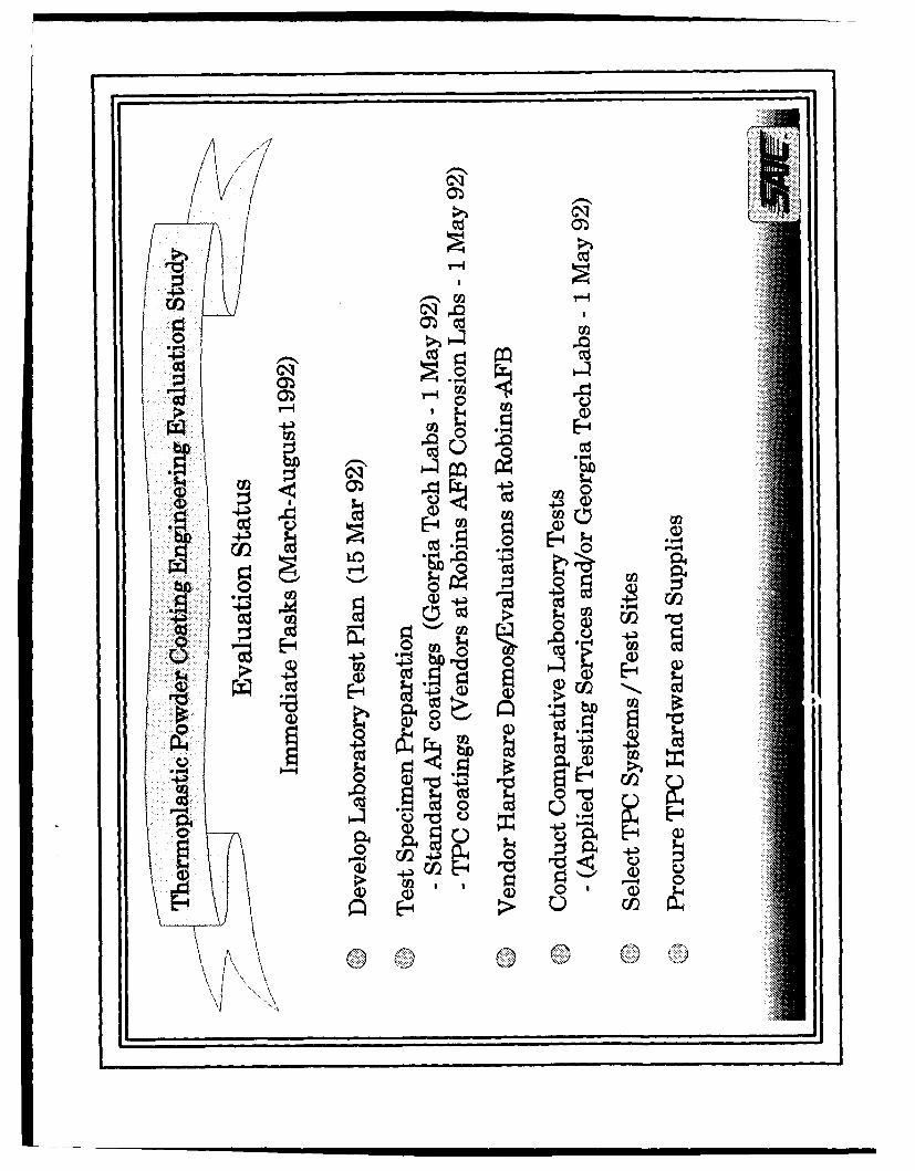
Phase I of the Environmentally Compliant Thermoplastic Powder CoatingEngineering Evaluation Study, Contract # F09603-90-D-2215, began on 24 Oct. 1991with a kickoff meeting at Warner Robins-ALC attended by SAIC and WR-ALC/CNC. Thepurpose of this meeting was to review the Statement of Work (SOW) and to establish aplan for the successful execution of this three-phase program. After a general programreview was completed, Phase I tasks were discussed and defined. This document, thePhase I Interim Engineering Report, reports progress in the completion of these tasks.
Phase I is broken into four sub tasks:
SUB TASK 1
Sub Task 1 involved identifying, contacting, and screening vendors ofthermoplastic powder coating (TPC) equipment, materials and technology. Also,personnel from the Air Logistics Centers at Ogden, San Antonio and Sacramento aswell as Wright-Patterson ALC Headquarters were contacted to inform them of theproject and to solicit their participation. The goal of the vendor search was to acquirecurrent information about the existing level of technology and the capabilities of TPCapplication hardware. The search consisted of surveying the Thomas Register forcompanies involved in powder coatings technology, reviewing powder coating industryliterature and contacting industry experts including the Powder Coatings Institute andDr. Jan Gooch, a polymer chemist who has worked with TPC technology for over tenyears. The Thomas Register search resulted in identifying and contacting 32companies. These contacts revealed that most listings were TPC applicators thatpurchased equipment and powders from a few actual hardware manufacturers. Manycontacts were involved in electrostatic deposition of powders or application ofthermoset plastics, technologies not included for consideration in the current SOW.
The vendor survey revealed that currently three basic options exist for thermalspray application of thermoplastic powders. The least developed technique, in termsof field-ready hardware, uses an inert gas plasma for heating the polymer powder. Thistechnique has successfully applied a wide range of thermoplastic and thermosetpolymers in the laboratory; however, the hardware is complex and expensive ($60,000for a basic unit). The two remaining technologies use a propane (home gas grill) oracetylene (cutting torch) flame to melt and flow the polymer coating. One of thesetechniques has evolved from the metal powder spray ("metallizing") industry which usesoxygen with acetylene or propane to achieve extremely hot flames suitable for meltingmetals. The oi;.;,r, simpler, method uses compressed air rather than oxygen. This
system operates with a "cooler" flame that is less likely to thermally damage the plasticpowder as it passes through the heating zone. All three of these TPC applicationtechniques use compressed gas (air or nitrogen @ 100 psig) to entrain powder from ahopper and to propel the powder through hoses to the flame/plasma gun. Portable,rugged production TPC application systems are currently available for both flamespraying techniques.
The screening process yielded five vendors as the consensus leading U.S.manufacturers of TPC equipment. They are:
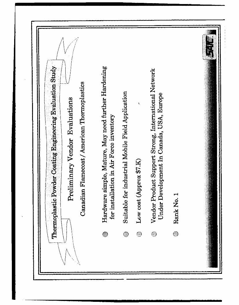
Canadian Flamecoat Systems/American Thermoplastics;
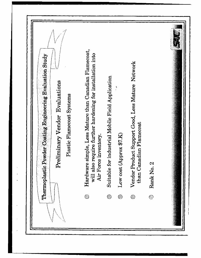
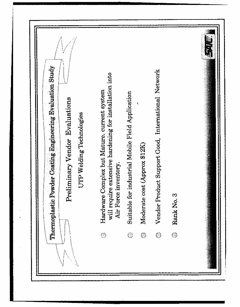
Canadian Flamecoat/American Thermoplastics, UTP and METCO have worked closelywith Dow Chemical to develop and optimize their systems using Dow "Envelon"ethylene acrylic acid (EAA) thermoplastic copolymers. Plastic Flamecoat has pursued asimilar cooperative arrangement with DuPont "Nucrel" ethylene methacrylic acid (EMAA)copolymers. EAA and EMAA are closely related polymers yielding similar physical andchemical resistance properties. They may be used interchangeably with the four flamespray systems listed above. Applied Polymer Systems has sprayed a variety ofthermoplastic and thermoset polymers from a variety of powder suppliers.
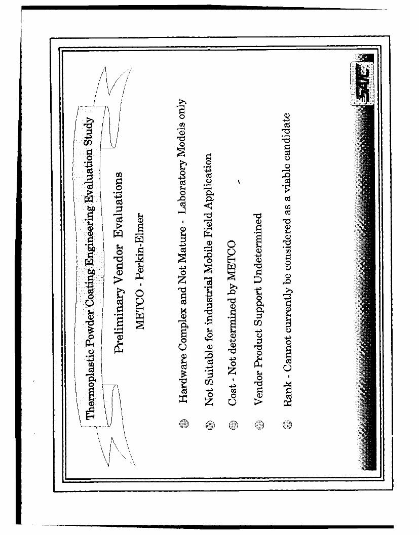
After completing the screening, SAIC visited the production facility of eachmanufacturer listed above to brief the project and to review that vendor's TPCapplication hardware. Each vendor was asked to complete the Vendor EvaluationChecklist (VEC) included as Attachment 1 to this document. Attachment 2 is asummary of the four flame-spray systems assembled from written responses to the VECas well as from actual interviews and observations made during equipmentdemonstrations. Attachment 2 also includes a summary of the Dow and DuPontcopolymers. It is apparent from the range of performance parameter values suppliedby the vendors that further equipment evaluation by SAIC and WR-ALC/CNC planned inPhase II of this program will be necessary to accurately characterize the systems. As abackup to the direct SAIC vendor review, Dr. Jan Gooch of the Georgia Tech ResearchInstitute (GTRI) was commissioned to assemble an independent overview reportdocumenting the current state of TPC equipment and material technology. Dr. Gooch's
2
findings augment and substantiate the SAIC conclusions. His report is included as
Attachment 3.
SUB TASK 2
Sub Task 2 is the development of a Site Evaluation Plan (SEP). The plan isincluded as Attachment 4 to this report. The SEP was written to insure thorough andconsistent evaluations of the potential U.S Air Force base field test sites for TPChardware. The original test sites were selected by WR-ALC/CNC from their highlycorrosive environments and range of climates. The originally selected installationswere;
Andersen AFB, Guam
Kadena AB, Japan
Osan AB, Korea
Sacramento ALC, California
This SEP was designed to asses the magnitude of the corrosion problem at each base,to evaluate the extent to which TPC technology can ameliorate the problem, todetermine base facility compatibility with TPC hardware and processes and to ascertainwhether sufficient manpower and skill levels exist to successfully operate TPCapplication equipment. Specifically, SAIC was tasked to consider the potential for TPCto replace the current solvent-borne coating systems used on munitions, munitionshandling equipment, mobile communications & electronic support equipment andaerospace ground equipment (AGE).
SUB TASK 3
The Site Evaluation Plan was implemented by visiting the four field locationslisted in Sub Task 2. The evaluation trip was conducted 7 January - 7 February 1992and included a vendor visit as well as additional briefings at the San Antonio ALC, KellyAFB and PACAF Headquarters, Hickam AFB, Hawaii. Results of this trip are reported indetail in Attachments 5 and 6 to this report. In summary, it was determined that asevere corrosion problem exists for all equipment, hardware and structures exposed toweather at Andersen AFB. The problem is compounded by continuing reductions inmanpower and budget. Any coating technique that can effectively extend corrosionprotection will be welcomed by base maintenance personnel. TPC will be most effectiveif used to coat equipment during periodic depot maintenance (PDM) when completeremoval of the original coatings and proper substrate preparation (sandblasting) can beaccomplished. Immediate applications for TPC evaluation include non-powered AGE
3
equipment, trailers, stands, bomb fins, training missiles, Rapid Assembly MunitionsSystems (RAMS), munitions containers, antenna masts, and Civil EngineeringStructures (exposed structural steel, bomb vault doors, revetment walls, storage tanks,pipelines, hand rails, etc.). Powered vehicles are also candidates if fuel/hydraulicsystems can be stripped (e.g. at PDM). Similar applications were identified at all bases.Corrosion at Kadena, while still a problem, is less severe than at Andersen, partlybecause the environment is less corrosive and partly because a more comprehensiveanti-corrosion program has been implemented. Osan's corrosion problem is lesssevere than Kadena and exists primarily as a result of salt and sand applied to theroads and other traffic areas during the winter to melt ice. SAIC has recommended thatan alternate cold weather test site with a more severe corrosion environment beconsidered to replace Osan (e.g., Shemya, Alaska).
SAIC determined that sufficient personnel skill levels for successful TPCapplication exist at every base and that no mechanical compatibility problems areevident. Compressed air and propane are locally available at each base. Since thesebases are remote on the supply pipeline, attention must be paid to insuring thatpowder and hardware replacement parts are available to the applicators.
Potential environmental problems were noted at two bases, Andersen andMcClellan. Andersen has experienced local EPA restrictions on outdoors sandblasting.Vacuum blasting is allowed, however, and SAIC recommends that a portable sandblastunit be provided with each TPC field hardware set to meet EPA requirements and toencourage and facilitate the use of the application equipment. The environmental groupat McClellan noted that nitrogen oxides are released as a result of the combustionprocess and that the base is restricted from adding new systems that release thesepollutants. This problem is not viewed as critical at this point since the TPC testequipment is not a permanent installation and is a very small source of NOx.
High levels of personnel interest and motivation were noted at all bases whenTPC technology was briefed. in general, the communications groups did not showgreat interest in TPC with the exception of those at the Sacramento ALC (McClellan)and Kadena.
The site evaluations were documented with 35 mm color prints and video tapeswhich have been submitted to WR-ALC/CNC. Final test site selection will be completedin Phase II of this program.
SUB TASK 4
SAIC has ranked and selected the following TPC equipment vendors for furthertest and evaluation:
1. Canadian Flamecoat/American Thermoplastics (Dow)2. Plastic Flamecoat Systems (DuPont)3. UTP Welding Technology (Dow)
4
The major weighting factors for hardware selection were:
1. Design Maturity2. Ease of operation3. Ruggedness (maintainability)4. Supportability (standard parts, vendor support network)5. Cost6. Polymer Compatibility
The systems selected represent a complete cross-section of current TPL, flame spraytechnology suitable for general industrial applications. Oxygen/fuel and compressedair/fuel systems are included as well as two major polymer powder suppliers. Eachvendor has been informed of their selection and lease arrangements are currently undernegotiation. One complete TPC application unit from each vendor will be delivered toWR-ALC/CNC for evaluation tests. These tests will last approximately six months andwill be conducted under Phase II of this program (April - September, 1992). These unitswill also be used to coat test panels for the laboratory coatings evaluation/comparisontests to be conducted at an independent lab under Phase II. The Test Plan for theselab tests is a Phase II deliverable item and is currently being written.
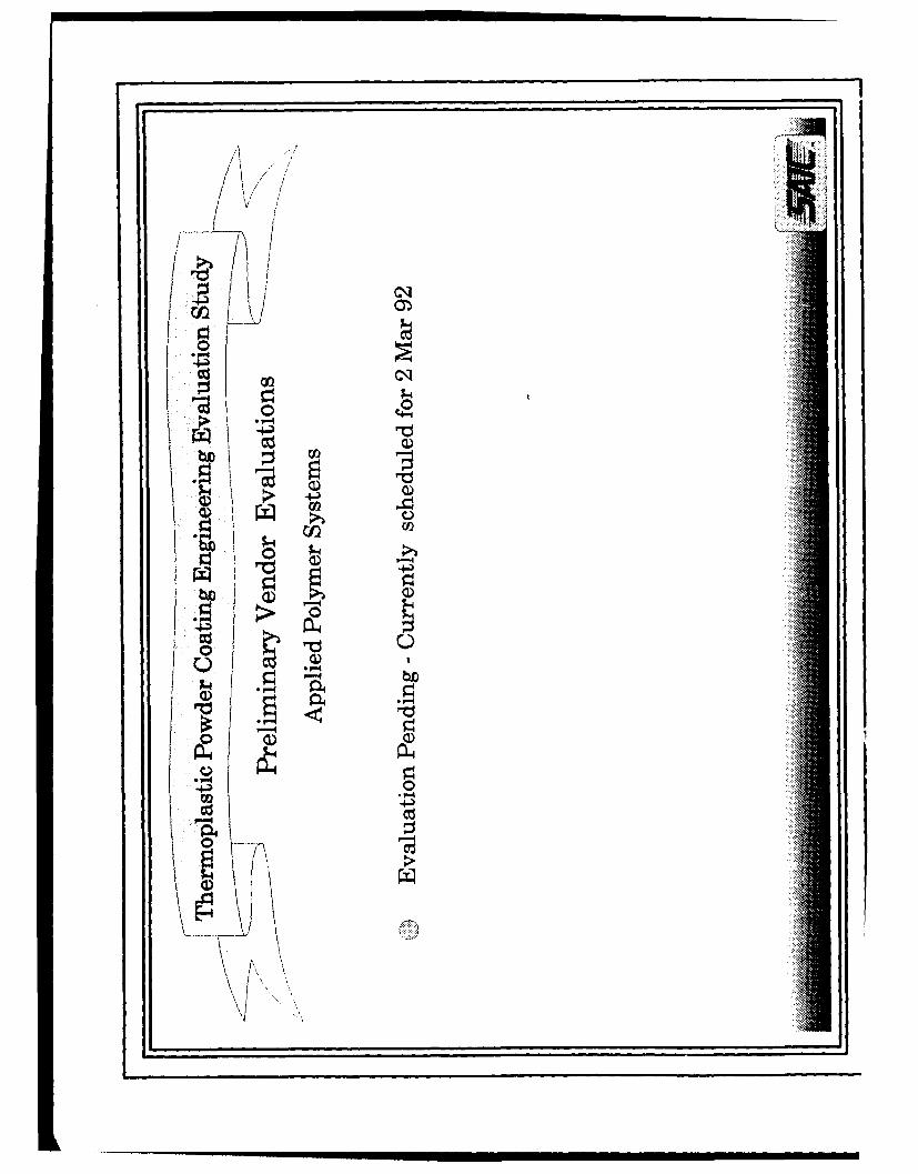
A complete briefing list is included as Attachment 7 to this report.
5
ATTACHMENT 1
Vendor Evaluation Checklist
VENDOR EVALUATION CHECKLIST (rev 11/27/91)
1. Obtain complete vendor literature describing processtechnology, hardware, performance data, field support andpricing.
etc.)1. Fuel consumption2. Fuel type/grade3. Electric power consumption4. Voltage/current5. Utility interface hardware compatibility
b. Maintenance/repair requirements1. MTBF2. Required service inspections, maintenance schedule3. Level of repair, field or depot4. Construction ruggedness
c. Vendor-supplier technical product/field support1. Program description2. Technical data/hardware upgrades3. Detailed technical support manuals with
assembly/parts breakdown (illustrated)4. Replacement parts, local compatibility
d. System costs1. original purchase2. Life cycle(including maintenance, repair)3. Operating ($/hr, $/sq ft, $/# coating - including
setup/use/cleanup cycle, also utilities, powder,fuel)
4. Replacement parts/componentse. System description
1. Size2. Weight3. Number of components4. Portability (air, ground; handling equipment
required)5. Shipment cube6. Construction (materials, fastenings etc.)
f. Delivery timeg. Warranty
1. Term2. Coverage
3. Determine process specifications/requirementsa. Required surface preparation (cleaning, blasting,
pretreatment, adhesion enhancers, corrosion inhibitors,preparation required for overcoating existingpolyurethanes/enamels/laquers)
b. Compatibility with existing coatings (as overcoat)
Vendor Evaluation Checklist Page 2 of 2
c. Application envelope (rate, ambleznt conditions,thickness, substrate type and conditirn, etc.). Definelimitations (potential problem areas and/or lessonslearned - vendor's expe.-ence)
d. Objec* piece size/conficjuration limitationse. Substrate/thermoplastic material temperature requirementsf. TPC material suppliers/availability/costg. Coating pigmentation capabilityh. coating $/sq ft appliedi. Environmental effects (cleanup, application, storage,
etc.)j. Application f _lpment power/utility/fue) consumptionk. Coating removc,&Aility (cold, hot, abrasives)i. Coating repairabilitym. Other system/process limitations, requirementsn. NDE/NDT' of surface/substrate with TPC (what thickness,
what nondestructive Lechniques/method'-/equipmentavailable)
4. Define and document other issuesa. Safety compliarr'e (OSHA, NIOSH, AFOSH)b. Environment/Bioenvironmentalc. Present level of technologyd. Vendor willingness to participate in technology R&D,
test and evaluatione. Operator skill level, training requiredf. Alternate application techniques (hot air, plasma, etc.)g. Existing test data -or coating effectivness (chemical,
environmental, corrosion)h. TPC materials availablei. Material property/performance data sheets (safe-..y,
physical properties, chemical resistance, corrosionprotection, durabilitiy, environmenLal resistance,application parameters etc.)
j. Conformance to attached MIL specs, standards and T.O.sk. Air Force special requirements/objections1. List of TPC equipment use,/customers
VENDOR: Canadian Flamecoat Systems Inc.412, 602-11 Avenue S.W.Calgary, Alberta, Canada T2RIJ8(403) 269-8530Contact: Mr. Randy MacKenzie, Vice President
American Thermoplastics, Inc.Dobson Executive Suites2266 South Dobson Road, Box "5"Mesa, Arizona 85202(602) 820-0528Contact: Mr. Randy Goesselin, President
GENERAL SYSTEM DESCRIPTION:
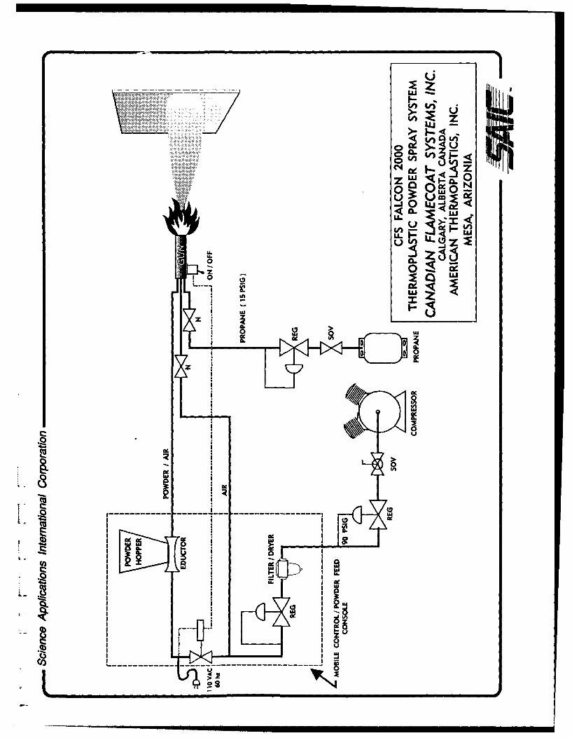
The CFS Falcon 2000 system is a transportable TPC flamespray unit capable of pallet-mounting. The CFS system usespropane gas and compressed air for combustion. The compressedair source transports thermoplastic powder from the storagehopper to the flamespray gun and provides combustion/cooling airto the gun. Manually operated regulators provide control of gasand air flow rates. An electic solenoid valve in the powderfeed line is operated with a switch on the flamespray gun toprovide on/off control. CFS recommends the use of Dow "Envelon"ethylene acrylic acid (EAA) copolymer thermoplastic powder withthis unit. The CFS system is described below and on the attachedschematic.
Maximum Coverage Rate (10 mil thick @ 5-7 mil/single pass,50% deposit efficiency): 150 sq ft/hr
Maximum Powder Consumption Rate(@ 10 mil thick, 50% deposit efficiency): 15 lb/hr
Applied Coating Weight @ 10 mil thick: 1 lb. per 20 sq. ft.
Canadian Flamecoat/American Thermoplastics - Page 2 of 2
NOMINAL UTILITY REQUIREMENTS*:
Fuel:Type: PropaneRate: 2.5 lb/hr (22 scfh)
Electrical:Type: 120 Vac, 60 Hz or 12 VdcRate: Less than 100 watts
Compressed Air: Information not available
NEW SYSTEM COST: $6,200.
TPC APPLICATION COST*: $8.00-$12.00/sq. ft.
Cost estimate based on Dow Chemical experience assumingpowder @ $15/lb, 15 mil coating applied at 10 ft 2/ib, 40ft 2/hron white metal blast substrate (two-man application team forblasting and coating @ $20./hr each).
MAINTENANCE/REPAIR COST*: Information not available.
MTBF*: Information not available.
ESTIMATED LIFE CYCLE COST*: Information not available.
SETUP TIME: 10 min.
CLEANUP/BREAKDOWN TIME: 10 min.
[ * NOTE: Values given are preliminary estimates. Actual valuesfor system performance parameters, application costs andoperation/maintenance costs to be determined during
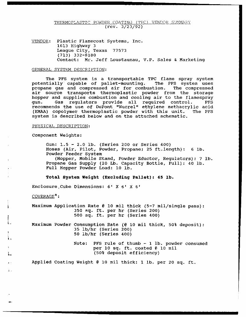
VENDOR: Plastic Flamecoat Systems, Inc.1613 Highway 3League City, Texas 77573(713) 332-8180Contact: Mr. Jeff Loustaunau, V.P. Sales & Marketing
GENERAL SYSTEM DESCRIPTION:
The PFS system is a transportable TPC flame spray systempotentially capable of pallet-mounting. The PFS system usespropane gas and compressed air for combustion. The compressedair source transports thermoplastic powder from the storagehopper and supplies combustion and cooling air to the flamespraygun. Gas regulators provide all required control. PFSrecommends the use of DuPont "Nucrel" ethylene methacrylic acid(EMAA) copolymer thermoplastic powder with this unit. The PFSsystem is described below and on the attached schematic.
PHYSICAL DESCRIPTION:
Component Weights:
Gun: 1.5 - 2.0 lb. (Series 200 or Series 400)Hoses (Air, Pilot, Powder, Propane; 25 ft.length): 6 lb.Powder Feeder System
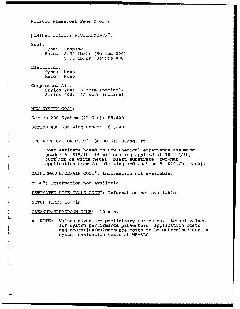
Cost estimate based on Dow Chemical experience assumingpowder @ $15/lb, 15 mil coating applied at 10 ft 2/lb,40ft 2/hr on white metal blast substrate (two-manapplication team for blasting and coating @ $20./hr each).
MAINTENANCE/REPAIR COST*: Information not available.
MTBF*: Information not Available.
ESTIMATED LIFE CYCLE COST*: Information not available.
K SETUP TIME: 10 min.
CLEANUP/BREAKDOWN TIME: 10 min.L
* NOTE: Values given are preliminary estimates. Actual valuesfor system performance parameters, application costsand operation/maintenance costs to be determined duringsystem evaluation tests at WR-ALC.
The UTPlast F-311 FX Gun and Flame Spray System is apotentially pallet-mounted mobile electro-pneumatic thermoplasticpowder spray application unit. The system uses either anacetylene/oxygen or propane/oxygen flame and a compressed airsource to both fluidize the thermoplastic powder and to propelthe powder through the flame. The powder fluidizer vesselenables the operator to dip-coat heated components as an optionto the normal spraying application. UTP recommends the use ofDOW "Envelon" ethylene acrylic acid (EAA) co-polymerthermoplastic powder with this unit. The UTP system is describedbelow and on the attached schematic.
PHYSICAL DESCRIPTION:
Component Weights:
Gun: 2.5 lb.Hoses (Oxygen, Propane,
Compressed Air; 20 ft. length): 15 lb.Powder Feeder/Gas Control System
(Mobile Stand with Regulators and Gages,): 100 lb.Propane Supply Bottle
Cost estimate based on Dow Chemical experience assumingpowder @ $15/lb, 15 mil coating applied at 10 ft 2/lb,40ft 2/hr on white metal blast substrate (two-manapplication team for blasting and coating @ $20./hr each).
MAINTENANCE/REPAIR COST*: Information not available
MTBF*: Information Not Available
ESTIMATED LIFE CYCLE COST*: Information Not Available
SETUP TIME: 15 min.
CLEANUP/BREAKDOWN TIME: 15 min.
V• * NOTE: Values given are preliminary estimates. Actual valuesfor system performance parameters, application costs andoperation/maintenance costs to be determined duringsystem evaluation tests at WR-ALC
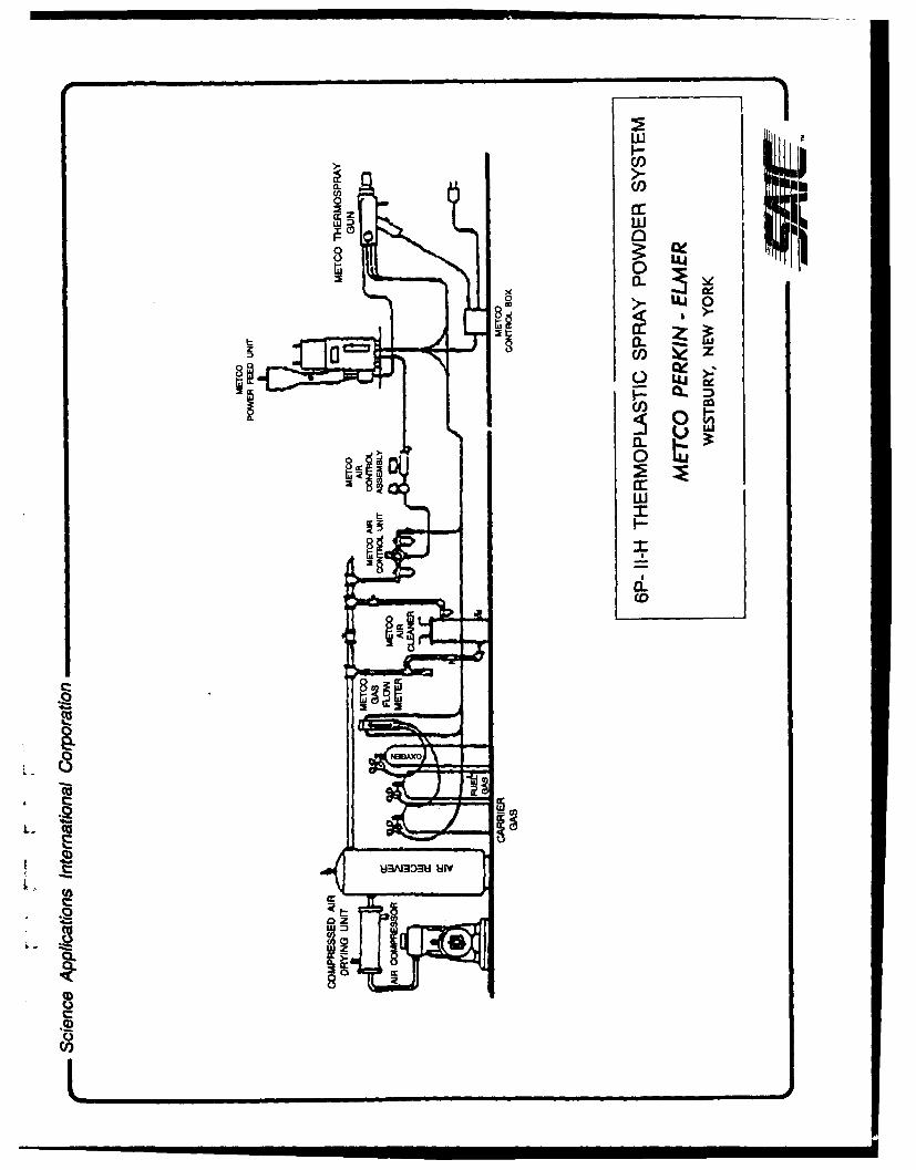
VENDOR: METCO (Division of Perkin Elmer)1101 Prospect AvenueWestbury, New York 11590(516) 334-1300Contact: Ms. Tuck Nerz, Materials Engineer
GENERAL SYSTEM DESCRIPTION:
The Metco 6P-II Thermoplastic Flame Spray System is apotentially pallet-mounted mobile thermoplastic powder sprayapplication unit. The system uses nitrogen gas to fluidize andtransport the thermoplastic powder to the gun and compressed airto cool the gun and propel the powder through an oxygen-propaneflame. METCO has developed this process and hardware using DowChemical ethylene acrylic acid (EAA) "Envelon" co-polymers. Thesystem is described below and on the attached schematic.
Maximum Application RateL (@ 10 mil thick, 5-7 mil/pass): 435 sq.ft./hr.
Maximum Powder Consumption Rate(@ 10 mil thick, 50% deposit efficiency):45 lb/hr
Deposited Coating Weight @ 10 mil thick: 1 lb./20 sq. ft.
METCO page 2 of 2
NOMINAL UTILITY REQUIREMENTS*:
Fuel:Type: propaneRate: 40 scfh
Electrical:Type: 120 Vac., 60 hzRate: 150 Watts each for 4MP feeder and 6PII contol box
Compressed Air:684 scfh @ 100 psig
Nitrogen:Requirements not available
Oxygen:78 scfh @ 18.6 psig
NEW SYSTEM COST:
Information not available
TPC APPLICATION COST*: $8.00-$12.00/sq. ft.
Cost estimate based on Dow Chemical experience assumingpowder @ $15/lb, 15 mil coating applied at 10 ft 2/lb,40ft 2/hr on white metal blast substrate (two-manapplication team for blasting and coating @ $20./hr each).
MAINTENANCE/REPAIR COST*: Information not available
MTBF*: Information not available
ESTIMATED-LIFE CYCLE COST*: Information not available
SETUP TIME: 15 min.
CLEANUP/BREAKDOWN TIME: 15 min.
* NOTE: Values given are preliminary estimates. Actual valuesL_ for system performance parameters, application costs
and operation/maintenance costs to be determined duringsystem evaluation tests at WR-ALC
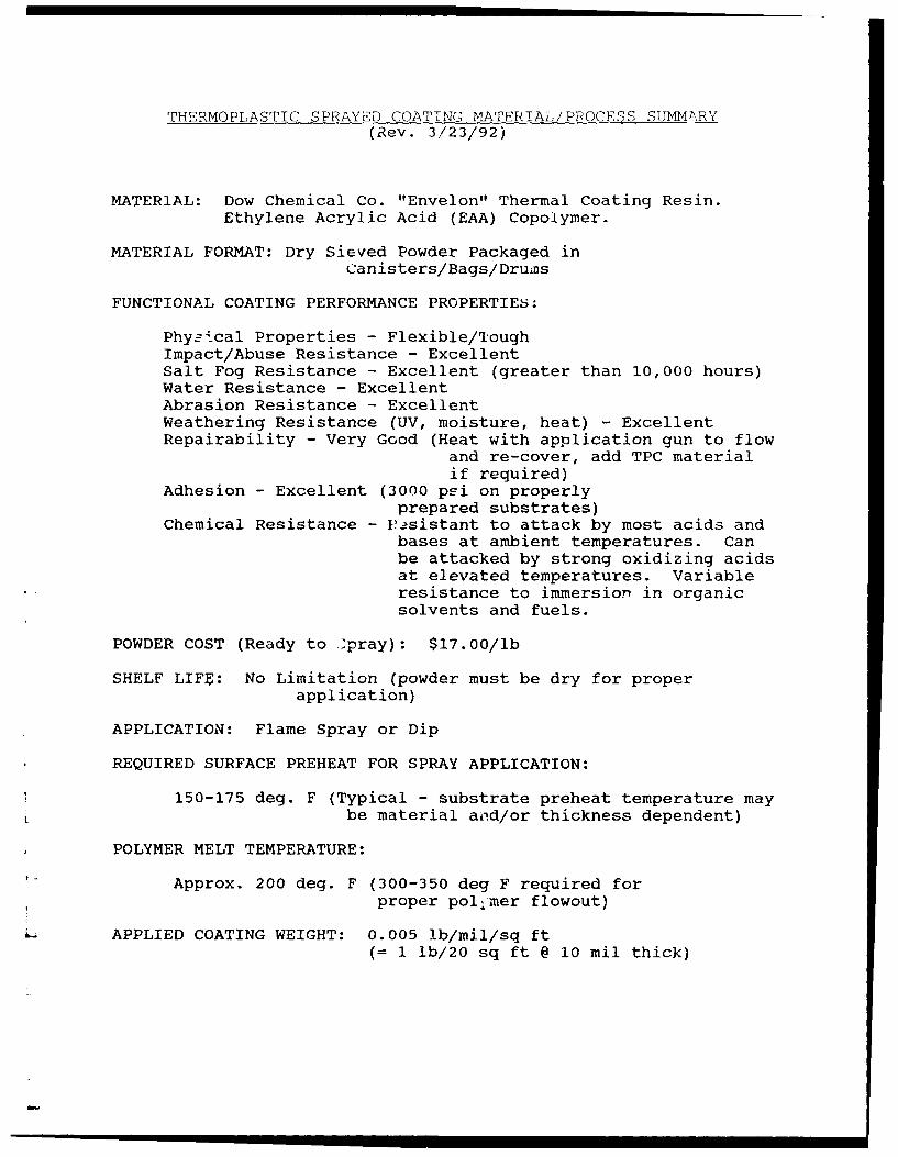
Phys4ical Properties - Flexible/ToughImpact/Abuse Resistance - ExcellentSalt Fog Resistance - Excellent (greater than 10,000 hours)Water Resistance - ExcellentAbrasion Resistance - ExcellentWeathering Resistance (UV, moisture, heat) - ExcellentRepairability - Very Good (Heat with application gun to flow
and re-cover, add TPC materialif required)
Adhesion - Excellent (3000 psi on properlyprepared substrates)
Chemical Resistance - P1sistant to attack by most acids andbases at ambient temperatures. Canbe attacked by strong oxidizing acidsat elevated temperatures. Variableresistance to immersion in organicsolvents and fuels.
POWDER COST (Ready to 'pray): $17.00/lb
SHELF LIFE: No Limitation (powder must be dry for properapplication)
APPLICATION: Flame Spray or Dip
REQUIRED SURFACE PREHEAT FOR SPRAY APPLICATION:
150-175 deg. F (Typical - substrate preheat temperature maySbe material and/or thickness dependent)
POLYMER MELT TEMPERATURE:
Approx. 200 deg. F (300-350 deg F required forproper pol~mer flowout)
L.APPLIED COATING WEIGHT: 0.005 lb/mil/sq ft(= 1 lb/20 sq ft @ 10 mil thick)
Dow TPC Page 2 of 2
RECOMMENDED SURFACE PREP:
SSPC-SP 6-85 commercial blast cleaning (1-3 mil anchorpattern, "white metal") Surface should be dry and free ofcontaminants. No primer required.
APPLICATION THICKNESS: 5-7 mil per pass
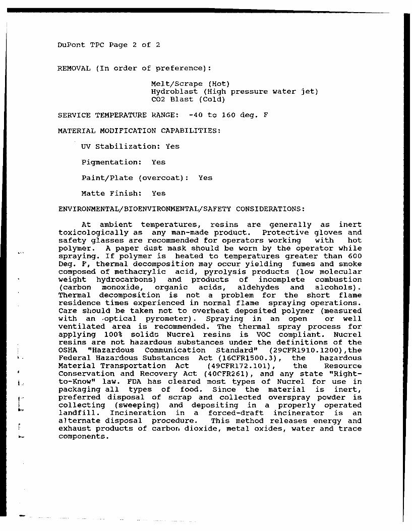
REMOVAL (In Order of Preference):
Melt/Scrape (hot)Hydroblast (high pressure water jet)C02 Blast (cold)
At ambient temperatures, resins are generally as inerttoxicologically as any man-made product. Protective gloves andsafety glasses are recommended for operators working with hotpolymer. .A paper dust mask should be worn by the operator whilespraying. If polymer is heated to temperatures greater than 600Deg. F, thermal decomposition may occur yielding fumes and smokecomposed of acrylic acid, pyrolysis products (low molecularweight hydrocarbons) and products of incomplete combustion(carbon monoxide, organic acids, aldehydes and alcohols). Thermaldecomposition is not a problem for the short flame residencetimes experienced in normal flame spraying operations. Careshould be taken not to overheat deposited polymer (measured withan optical pyrometer). Spraying in an open or well ventilatedarea is recommended. The thermal spray process for applying100% solids Envelon resins is VOC compliant. Envelon resins arenot hazardous substances under the definitions of the OSHA"Hazardous Communication Standard" (29CFR1910.1200), the FederalHazardous Substances Act (16CFR1500.3), the hazardous MaterialTransportation Act (49CFR172.101), the Resource Conservation andRecovery Act (40CFR261), and any state "Right-to-Know" law. FDAhas cleared most types of Envelon for use in packaging all types
U of food. Since the material is inert, preferred disposal ofscrap and collected overspray powder is achieved by collecting(sweeping) and depositing in a properly operated landfill.Incineration in a forced draft incinerator is an alternatedisposal procedure. This method releases energy and exhaust
dcs of carbon dioxide, metal oxides, water and trace
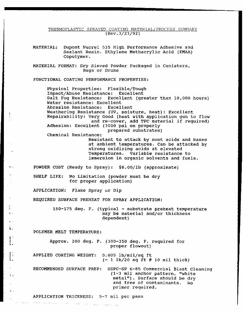
MATERIAL FORMAT: Dry Sieved Powder Packaged in Canisters,
Bags or Drums
FUNCTIONAL COATING PERFORMANCE PROPERTIES:
Physical Properties: Flexible/ToughImpact/Abuse Resistance: ExcellentSalt Fog Resistance: Excellent (greater than 10,000 hours)Water resistance: ExcellentAbrasion Resistance: ExcellentWeathering Resistance (UV, moisture, heat): ExcellentRepairability: Very Good (heat with application gun to flow
and re-cover, add TPC material if required)Adhesion: Excellent (3000 psi on properly
prepared substrates)Chemical Resistance:
Resistant to attack by most acids and basesat ambient temperatures. Can be attacked bystrong oxidizing acids at elevatedTemperatures. Variable resistance toimmersion in organic solvents and fuels.
POWDER COST (Ready to Spray): $8.00/lb (approximate)
SHELF LIFE: No Limitation (powder must be dryfor proper application)
APPLICATION: Flame Spray or Dip
REQUIRED SURFACE PREHEAT FOR SPRAY APPLICATION:
150-175 deg. F. (typical - substrate preheat temperaturemay be material and/or thicknessdependent)
POLYMER MELT TEMPERATURE:
$ Approx. 200 deg. F. (300-350 deg. F. required forproper flowout)
APPLIED COATING WEIGHT: 0.005 lb/mil/sq ftL• (= I lb/20 sq ft @ 10 mil thick)
RECOMMENDED SURFACE PREP: SSPC-SP 6-85 Commercial Blast Cleaning(1-3 mil anchor pattern, "whitemetal"). Surface should be dryand free of contaminants. Noprimer required.
APPLICATION THICKNESS: 5-7 mil per pass
DuPont TPC Page 2 of 2
REMOVAL (In order of preference):
Melt/Scrape (Hot)Hydroblast (High pressure water jet)C02 Blast (Cold)
At ambient temperatures, resins are generally as inerttoxicologically as any man-made product. Protective gloves andsafety glasses are recommended for operators working with hotpolymer. A paper dust mask should be worn by the operator whilespraying. If polymer is heated to temperatures greater than 600Deg. F, thermal decomposition may occur yielding fumes and smokecomposed of methacrylic acid, pyrolysis products (low molecularweight hydrocarbons) and products of incomplete combustion(carbon monoxide, organic acids, aldehydes and alcohols).Thermal decomposition is not a problem for the short flameresidence times experienced in normal flame spraying operations.Care should be taken not to overheat deposited polymer (measuredwith an .optical pyrometer). Spraying in an open or wellventilated area is recommended. The thermal spray process forapplying 100% solids Nucrel resins is VOC compliant. Nucrelresins are not hazardous substances under the definitions of theOSHA "Hazardous Communication Standard" (29CFR1910.1200),theFederal Hazardous Substances Act (16CFR1500.3), the hazardousMaterial Transportation Act (49CFR172.101), the ResourceConservation and Recovery Act (40CFR261), and any state "Right-to-Know" law. FDA has cleared most types of Nucrel for use inpackaging all types of food. Since the material is inert,preferred disposal of scrap and collected overspray powder is
L collecting (sweeping) and depositing in a properly operatedlandfill. Incineration in a forced-draft incinerator is analternate disposal procedure. This method releases energy andexhaust products of carbon dioxide, metal oxides, water and tracecomponents.
ATTACHMENT 3
i Survey Report
r.
I,
L¶L
r
SURVEY OF THERMOPLASTIC POWDER COATINGS (TPC)TASK 1
Prepared For
Science Applications International Corporation2220 Northwest Parkway, Suite 200
Marietta, Georgia 30067
Contact: Dr. Douglas NealeTele: (404) 952-7002Fax: (404) 952-6920
Prepared By
Dr. Jan W. GoochV- Polymers & Coatings Consultant
85 Chaumont Square NWAtlanta, Georgia 30327
Tele: (404) 355-1467Fax: (404) 894-6199
L
February 17, 1992
k
Table of Contents
Page
1.0 INTRODUCTION 1
1.1 General 1
?.0 STATEMENT OF WORK 1
Task 1 - Conduct a Literature Search 1Task 2 - Write a Summary of Findings 1Task 3 - Assemble a List of Vendors/ 1
Suppliers
3.0 RESULTS 1
3.1 Results of Task 1 13.2 Results of Task 2 23.3 Results of Task 3 7
v 4.0 CONCLUSIONS 8
5.0 RECOMMENDATIONS 8
6.0 PROPOSAL FOR FLAMELESS SPRAYING OF 9TPC COATINGS
7.0 REFERENCES 10
Appendix A - Vendors/Suppliers Contacted
L.
Si i I I I I I I IIIII
List of Tables
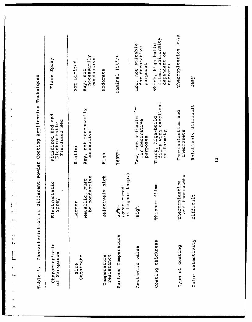
Table 1. Characteristics of Different Powder Coating ApplicationTechniques
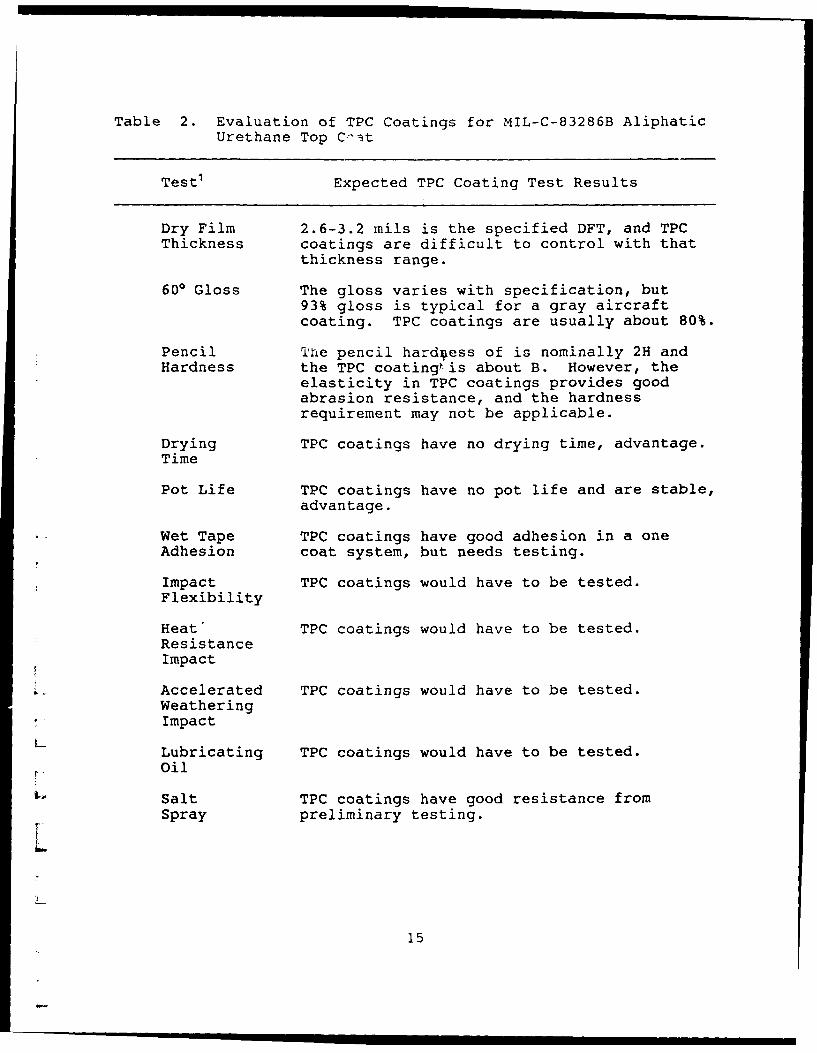
Table 2. Evaluation of TPC Coatings for MIL-C-83286B AliphaticUrethane Top Coat
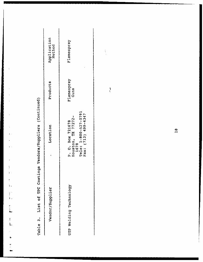
Table 3. List of TPC Coatings Vendor/Suppliers
List of Figures
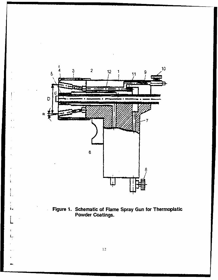
Figure 1. Schematic of Flame Spray Gun for Thermoplastic PowderCoatings
fI
L
"L
ii
1.0 INTRODUCTION
1.1 General
The general scope of this subject including subsequenttasks assigned to Dr. Gooch is centered around identification offlame sprayed thermoplastic coatings to replace solvent-bornecoatings. Conventional coatings used by the U. S. Air Force havebeen water- and solvent based, and the latter being the mostwidely used. Solvents produce volatile organic compounds (VOC)which are objectionable because environmental and health reasons.
2.0 STATEMENT OF WORK
Task 1 - Conduct a Literature Search
Conduct a literature search and assemble pertinent documentsdescribing current technology for sprayed thermoplastic powdercoatings including techniques, materials and applicationshardware.
Task 2 - Write a Summary of Findinos
Write a narrative summarizing and evaluating the technologydocumented in Part A. Include potential benefits, drawbacks andlimitations of this technology for the U. S. Air Force in itscorrosion prevention/protection programs (particularly formunitions handling equipment, mobile communications/electronicshardware an aerospace ground equipment). Discussion shouldinclude the requirements for application of thermoplastics onuncoated and previously coated (thermoplastic or conventional,damaged/undamaged) substrates at depot and field levelfacilities. Finally, the potential for near-term development ofTPC technology hardware and materials should be assessed.Techniques that eliminate application of TPC with open flames areof particular interest.
Task 3 - Assemble a List of Vendors/SuppliersLAssemble a comprehensive listing of current active TPC
vendors and material suppliers. Where possible, assessvendor/supplier viability and level of technology.
L 3.0 RESULTS
3.1 Results of Task 1
L Dr. Gooch conducted a literature search of flame spray
' II I I I I I1
processes and equipment describing current technology for sprayedthermoplastic powder coatings including techniques, materials andapplication hardware.
3.2 Results of Task 2
General information on thermoplastic powder coatincs
Flame spraved TPC coatings
The flame-spray coating technique has been developedwithin the about last twelve years for application forapplication of thermoplastic powder coatings. Polyethylene,copolymers of ethylene and vinyl acetate, nylon and polyesterpowder coatings have been successfully applied by flame spraying.This technique permits powder coatitigs to be applied topractically any substrate, since the coated article does notundergo extensive additional heating to ensure film formation.In this way, substrates such as metal, wood, rubber and masonrycan be successfully coated with powders if the coating itself hasa proper adhesion to the substrate. The technique itself isrelatively simple:
a. Powder coating is fluidized by compressed air and fedinto the flame gun.
b. The powder is then injected at high velocity through aflame of propane. The residence time of the powder inthe flame and its vicinity is short, but just enough toallow complete melting of the powder particles.
c. The molten particles in the form of high viscosityýroplets deposit on the substrate forming high-buildfilm upon solidification.
An example of a flame-spray gun disclosed in a patent ofOxacetylene Equi (S.U. Patent 1423176, 1985) is sketched inFigure 1. The gun has a body (1) with air (7), combustion gas(9) and powder material (5) supply channels. The outlet of thepowder channel is axially positioned at the gun mouthpiece (3)with the channels for the combustion gas outlet situated at equaldistances on the circumference concentric to the axial powderchannel. The efficiency is increased by preventing the powderfrom burning in the flame since the concentric circumferencediameter is 2.85-4.00 times the powder outlet channel diameter.The coating quality is increased when using liquified gas sincethe combustion gas outlet channel axis is at 6-90 to the powderchannel axis, forming a diverging flame. The amounts of air andcombustion gas are regulated by valves (8 and 10). The airpasses through rough ejectors (11) creating a refraction in thechannel (9). The air and liquified gas mix in chambers (12)forming a combustible mixture which flows to the mouthpiece
2
nozzles (4). The powder particles entering the flame are heatedand in a molten form are supplied onto the surface being coated.
Since the flame spray process does not involve oven heatingit is very suitable for field application on workpieces which arelarge or permanently fixed and this not able to fit inside anoven. It has been reported that objects such as bridges,pipelines, storage tanks and railcars are suitable surfaces to becoated by this technique. The nominal coating thicknessesreported are 3-5 mils and 6+ mils for most applications.
Plasma spraying of TPC coatings
The plasma spraying process of TPC coatings utilize argongas passing through an electric arc between an anode and acathode. The carrier gas loses onejof its electrons and becomesa highly energetic, extremely hot and glowing plasma. As theplasma leaves the internally water cooled plasma generator in thegun, powdered thermoplastic formulations and inert gas areintroduced into the stream in a precisely controlled manner. Asthe material is entrained in the high velocity and hot plasmastream, it Luecomes molten and is projected against the surface ofthe substrate at subsonic or supersonic speeds. When individualparticles impact against the surface at high speeds, thermal andmechanical energies are transferred to the substrate, producingforces which favor bonding The minimum reported film thicknessis 2 mils.
The basic difference between the plasma and flame sprayingtechnologies is that the former utilizes an electrical arc toheat an inert gas producing a hot and glowing stream of gas, andthe latter a combustible gas producing a flame. The hot gasstreams are necessary to heat the substrates and the TPC coatingsto produce a film. The hot glowing gas from neither process isattractive due to fire hazards.
The equipment for this technology is bulky and the operator-. requires extensive training. The application of TPC coatings is
recommended for depot level only.
L Advantages/disadvantages of TPC coatings
A comparison to other generic powder coatings methods isL contained in Table 1. Important advantages/disadvantages are
discussed below with reference to Table 2.
Advantages:
a. The larger sizes of the substrates are not limited, butsmall objects are difficult to coat.
L b. The key attribute of the plastic flamespray process
3
versus electrostatic powder coatings is that coatings may be
applied and repaired in the field.
c. There are no volatile organic compounds, 100% solids.
d. The flame sprayed thermoplastic powder coatings haveexcellent environmental weathering resistance.
e. Moderately skilled labor is required to operate theequipment.
f. TPC coatings do not have a drying, curing time or potlife, this presents a savings in time and extends shelf life.
g. TPC coatings can be recoated immediately since there isno drying or curing time.
h. TPC coatings can be applied with a single coat andusually require no primer coats.
i. The capital investment is low (about $7000).
j. The color is easy to change or modify since pigments canmixed in the powder feed in small batches; this is not convenientfor electrostatic applied coatings since the batches are largeand the dielectric properties are critical as noted in Table 1.
Disadvantages:
a. The open flame cannot be used near any volatilesubstance (e.g., fuel) or equipment containing such substancesincluding aircraft and motorized ground vehicles. Even theelectrically induced plasma spray developed by Applied PolymerSystems produces the same fire hazard.
b. Complicated shaped parts are difficult to coat.
L. c. The melting of a thermoplastic material in an open flamecan degrade some polymers and produce hazardous gases. Degraded
r (burned) polymer particles provide a flaw within the film.
d. The surface temperature of metals substrates must be150OF or greater to form a smooth film. Lower temperatures willcause a rough surface.
e. The film thicknesses of flame sprayed thermoplasticpowder coatings are large (nominal 6 mils+) in comparison tosolvent-borne and electrostatic deposited films. The MIL-C-83286B aliphatic urethane specifies a total dry film thickness of2.6-3.2 mils. TPC coatings are compared to MIL-C-83286B in Table
L 2. The weight of the film is greater due to thicker filmthickness which can be a factor for aircraft and equipment which
4
must be airlifted. The densities (about 0.93 g/cm3 ) of TPC andsolvent-borne coatings are similar.
f. The glass transition temperature (cold embrittlement) ofthe thermoplastic coatings on aluminum panels was measured by theauthor and found to be higher (approx. 00 F) than vendor reportedvalues (approx. -60 0F). This could be a serious problem incolder climates since the impact resistance would be minimal.
g. The removal of these coatings cannot be accomplishedusing the standard paint removal chemicals. Typically, thecoating is heated to its softening temperature (nominally 220 0 F)and scraped off the surface. The author discovered a cryogenicmethod of removing the material which includes cooling thecoating below its glass transition temperature while abradingwith plastic pellets. Abrasive cleAning with plastic media belowthe embrittlement temperature is a potential method of removingthese TPC coatings.
h. The hardness of the flame spray thermoplastic coating islow, but the abrasion resistance is good. If a specificationrequired a certain hardness, then the coating would not besuitable or the specification would have to be modified.
Munitions handling ecquipment I
Generally, TPC coatings are not immediately useful for thisapplication due to the high and unpredictable temperatures onmetal surfaces. Also, the open flame is menacing. A hot inert
7 gas system is recommended for this application where the* temperature can be well controlled. The temperature range for
munitions is -65 0 F to 1651F (reference General Purpose BombsT. 0. li-A-15-I-1-57). Applied Polymer Systems has a potentialsolution to the temperature extremes which is deserving ofinvestigation, but the surface temperature is still about 150 0 F.The reported (David Ellicks of WR-ALC) specification for paintinggeneral purpose bombs is MIL-C-83286B, the maximum DFT is 3.2mils, requires quick drying, and the lowest controllable flamesprayed TPC coatings is 3-5 mils. Applied Polymer Systems, Inc.reported a minimum thickness of 2 mils using a carbon arc plasma
L_ sprayed TPC coating.
Mobile communications/electronics hardware
The final report entitled "Evaluation of Coating Systems forAir Force Vehicles and mobile Equipment" (referenced in section7.0) was reviewed before making the following comments. Theauthor refers the reader to the thorough investigation of surfacepreparation practices and coating materials discussed in this
I" report. Some of the most widely used coating systems are* urethanes (MIL-C-83286B); and alkyds (TT-E-489, TT-E-490, TT-E-
527, TT-E-529 and others). Alkyds are particularly heat
5
sensitive, and TPC coatings cannot be applied over either ofthese coatings since blistering would be expected.
Color formulating for TPC coatings is not reported todifficult, which is important since color schemes are alreadyestablished. The film thickness requirement will be a problem,but modification to the coatings could conceivably solve thisproblem. Referring to T.O. 1-1-689 for avioncs and electronicsequipment, the dry film thickness (DFT) is 3.2 mils ofepoxy/urethane which is lower than typical flame spraythicknesses. The carbon arc plasma sprayed thermoplasticcoatings technology from Applied Polymer System, Inc. equipmentis reported to be capable of applying films of a minimumthickness of 2 mils. Other flame spray technologies could beused if the films thicknesses in the specification wereincreased.
Aerospace ground equipment
Unmotorized equipment is a candidate for coating with TPCmaterials. Referring to T.O. 35-1-3 for flightline tow carts,etc, the maxiumum DFT thickness is 3.2 mils of epoxy/urethane,and most flame sprayed films produce a minimum films thickness of3-5 mils. If the specification was changed to increase filmthicknesses, then flame spray TPC coatings could be used. TheApplied Polymer Systems, Inc. technology reported a minimum filmthickness of 2 mils.
Referring to T.O. 36-1-3 for trucks and others, the maximumDFT is 3.2 mils of alkyd enamel or epoxy/urethane. For mobileshelters there is not a directive for corrosion protection.
Referring to MIL-P-26915B for zinc dust pigmented primercoatings, and Federal Specificatioin TT-E-529 for semi-glossalkyd coating, the total film thickness is about 3.2 mils.
In summary, whether alkyd enamels or epoxy/urethane coatingsystems are utilized on equipment, the coating thickness is neverover 3.2 mils unless the equipment is recoated. All otherrequirements such salt spray resistance would have to be tested.
In addition, the chromaticity requirements (referring tot- MIL-C-46168D) could feasibly met be using TPC coatings.
Flameless TPC Coating System
L At present, there is no commercially available flameless TPCcoating systems, a proposal is enclosed to develop a prototypeunit.
6
3.3 Results of Task 3
Vendors/Suppliers of TPC Coatings
Vendors
A list of vendors and suppliers of thermoplistic coatingsequipment and materials are contained in Table 3. The total listof vendors/suppliers contacted are contained in Appendix A. Thevendors/suppliers published information is supplied underseparate cover.
Referring to Table 3, the flamenspray equipment vendors are:1.
Actvr.lly, the technology from Applied Polymer Systems, Inc.is a electrically generated arc type plasma rather than acombustible gas flame like the others. The most active of theabove vendors appears to be Canadian Flamecoat Co. and PlasticFlamecoat, Inc.
Applied Polymer Systems, Inc. has the only plasma sprayV system that has been reported to the author.
Suppliers
Suppliers of the TPC (ethylene-acrylic acid copolymers)coatings are Dow Chemical Co. and DuPont Polymers Co. These arethe leading suppliers of TPC materials, and vendors purchase
* these materials and customize them for their specific uses. Non-ethylene-acrylic acid copolymer TPC coatings are supplied byCelanese Co., Atochem and others.
L Coating and Recoating
Flamespray coating of metal surfaces such as steel requicesa cleaned surface (SSPC-SP-10 near-white or SSPC-SP-5 white metalblast). Aluminum with protective chemical conversion coatings(MIL-C-5541) cannot be abrasively cleaned except with plasticmedia, and coatings on these surfaces are usually removed withchemical strippers. Aluminum without chemical conversioncoatings must be cleaned with chemical strippers or abrasivelyusing abrasive media which will not damage the surface sincealuminum is softer than steel. The reader is referred to areport entitled "Evaluate and Document Lead Paint Abatement"
7
referenced in section 7.0 for vacuum abrasive cleaningtechnologies and equipment. Flamespray coating of surfacescoated with conventional solvent- or water-borne coatings is notrecommended because the heat may produce blistering. Recoatingof previously flamespray coated surfaces is recommended afterlight abrasive cleaning to remove contamination. Repairs may beperformed on damaged TPC coatings if the TPC coatings areidentical in composition, excluding colors. Flamespray coatingcan be conducted in the field or at depot level.
Near-term development of equipment
Flamespray equipment is developed to provide field and depotlevel coatings, and the equipment usually sells for less than$7000. The electric arc plasma spray of TPC coatings isdeveloped, but the equipment is larqer and more expensive andsells for $70,000 with a technology license or a leasearrangement at about $1500/month.
4.0 CONCLUSIONS
The disadvantages of the TPC coatings have been discussedabove. It is felt that the tremendous advantages that TPCcoatings offer far out weigh the disadvantages. For some ferroushardware items, TPC coatings are already a viable solution forcorrosion prevention.
More information is required on the application rates andcosts of the flame and plasma sprayed TPC coatings undercontrolled conditions. There has been a wide range of reportedinformation for application rates and costs.
5.0 RECOMMENDATIONS
In order to make flame spray thermoplastic powder coatingsusable for munitions handling equipment, the substratetemperature would have to be reduced below 150 0 F. The margin oferror would still be too low due to the potential propane flametemperature of 1800'F+ (point temperature). A propane flamecontains zones of temperature due to the oxidation process. Itis recommended that this application be delayed until a lowtemperature method is perfected.
The coating thicknesses on mobile communications/electronicshcrdware and aerospace ground equipment would be difficult to
L control by the present flame sprayed thermoplastic coatingsprocesses. To use the processes, it would be necessary to revisethe specifications or modify the thermoplastic powder coatings.One method of controlling the coating thicknesses is to decrease
L the powder particle size and maintain a narrow particle
8
distribution.
The inherent open flame of the flame spray thermoplasticcoatings processes will not lend itself to areas where volatilematerials (e.g., fuel) are present. In addition, cquipment whichpossesses elastomeric seals, undercoatings will be damaged by theflame.
It is strongly recommended that a noncombustible hot-air orinert gas (e.g., nitrogen) be used as the spraying medium toeliminate a flame and reduce point temperature. It is recommendedthat the melt flow index of the powders be reduced to providelower viscosity at lower temperature to provide lower applicationtemperatures and thinner coatings. This will require analteration in the composition of the powder coating materials.The higher melt viscosity index (legs viscosity) powders wouldproduce a softer coating, but a post-curing agent could be addedto compensate for that property. This could be accomplished bycrosslinking less than one percent of the total weight of thecoating. Recoating or repairing of the coating would not besignificantly impaired.
6.0 PROPOSAL FOR FLAMELESS SPRAYING OF POWDER COATINGS
The author proposes a flameless and safe method of sprayingthermoplastic and thermoset powder coatings on metal substrateswith causing any fire hazards even in the presence of fuelspills. The basic concept is explained as follows:
a. A electrically (nichrome element) heated steam of inertgas (nitrogen or argon) is generated in an enclosedinsulated housing; an electrical generator must beconsidered for field use.
b. A steam of TPC particles enters a mixing nozzle withthe gas stream at about 1500OF inducing a molten state
V within the particles.
r c. The particles strike a substrate (100 0 F) and flow outto form a film.
d. The properties of the TPC coatings must be altered toprovide a higher melt flow index (less viscosity)without altering the properties of the final coating.
A prototype flameless TPC coater will require one year ofdevelopment.
9
7.0 REFERENCES
Military Specifications
MIL-P-23377 Primer Coatings: Epoxy, Chemical andSolvent- Resistant
MIL-M-38784 Manuals, Technical: General Requirements forPreparation Of
MIL-P-38790 Printing Production of Technical Manuals:General Requirements For
MIL-M-3910 Manuals, Technical: Illustrated PartsBreakdown: Preparation Of
MIL-STD-961C Military Specification and AssociatedDocuments, Preparation Of
MIL-STD-1388-1A Logistics Support Analysis
10
Reports
Development of Environmental Protection Agency Compliant,Corrosion-Inhibiting, Aircraft Coating System, Georgia TechResearch Institute, Atlanta, Georgia, 5 February 1989.
Evaluate and Document Lead Paint Abatement, Government ContractNo. DACA88-90-D-0006-0008, Georgia Tech Research Institute,26 August 1991.
George, E. R., "Thermoplastic Powder Coatings," Proceedings ofthe Water-Borne & Higher Solids Coating Symposium, New Orleans,Louisiana, 6-8 February, 1991.
Evaluation of Powder Coatings, Contract No. TR515-536, SheldonToepke, McDonnell Aircraft Company, St. Louis, Missouri.
Evaluation of Coating Systems for Air Force Vehicles and MobileEquipment, Contract No.0024-86-D-4306, ARINC ResearchCorporation, Annapolis, Maryland.
Personal Communications
Tor Aasrum of Jotun Corro-Coat, Larvik, Norway, 9 January 1992.
Ad Hofland of DSM Resins BV, Zwolle, The Netherlands, 6 January1992.
L .
11
V
1 27
8
IILFigure 1. Schematic of Flame Spray Gun for ThermoplaticL Powder Coatings.
12
>4
0
>4+ 4-)4) fl440 .'-4>1 '-D0 *'-i0 (a 1-1
(a '0 *-> 0 :34 Z r--) ca0) $4 -4 0 (a0 t04 r~-j w )
(0a 4 04.) U a) (1) 0) -rq 4.) (A U 4) 4-) 4) CC -04 ~E 0 En 4-) 010O 0 D0 0
4-) ra u : 04 (a~4 to)ED4a -,I Q)- 04 4)O0N 0 0 >10 •o -, ,r (a ro c04Li -I 0 0 4)
04 -4>
*004
4-3 0 -4C: .- r-40 4J 0 41
S) 41 )O .14 4-) 4)w- ( 0 Vc 0 4) 4)(D 41) 4. (o 4., H
*4-4 U) u . 4-) 4-i4-4 0 >1 4)x C ~>4 w 4-).14 w to 41 0 *-4 -- 4 V 0--
i1 w (a wm En C na)n
44 0a -r40 (014-4).) V)04 --- 44) >1>4
r)0 0 C)
-- 4
U4)
04
4) -4 wt4) 4) 0 r. (a
4--) 4 4.)0L.~L Li I-4 0 u)U
(a 0 4)
C1 4-i 0u1- 0 04
to 4.) 01-
E-0 Li0 044)
Table 2. Evaluation of TPC Coatings for MIL-C-83286B Aliphatic
Urethane Top C-it
Test' Expected TPC Coating Test Results
Dry Film 2.6-3.2 mils is the specified DFT, and TPCThickness coatings are difficult to control with that
thickness range.
600 Gloss The gloss varies with specification, but93% gloss is typical for a gray aircraftcoating. TPC coatings are usually about 80%.
Pencil The pencil hardness of is nominally 2H andHardness the TPC coating?.is about B. However, the
elasticity in TPC coatings provides goodabrasion resistance, and the hardnessrequirement may not be applicable.
Drying TPC coatings have no drying time, advantage.Time
Pot Life TPC coatings have no pot life and are stable,advantage.
Wet Tape TPC coatings have good adhesion in a oneAdhesion coat system, but needs testing.
Impact TPC coatings would have to be tested.Flexibility
Heat' TPC coatings would have to be tested.ResistanceImpact
Accelerated TPC coatings would have to be tested.WeatheringImpact
Lubricating TPC coatings would have to be tested.
Oil
Salt TPC coatings have good resistance fromSpray preliminary testing.
L
15
Table 2. Evaluation of TPC Coatings for MIL-C-83286B AliphaticUrethane Top Coat (Continued)
Testi Expected TPC Coating Test Results
Humidity TPC coatings should have good resistance,Resistance but require complete testing.
Low TPC coatings of the ethylene-co-acrylicTemperature acid composition have not tested extensively,Flexibility but -40OF to 160OF service ranges have been
reported.
Hydrocarbon TPC coatings wohld have to be tested.Resistance
Hydraulic TPC coatings would have to be tested.FluidResistance
Skydrol TPC coatings would have to be tested.500 BResistance
Distilled TPC coatings have good resistance.Water
1. MIL-C-83286B/MIL-P-23377D system
V
L
L
16
0o> >1
41Jt 14 w- (a $4(a0 04.. 0.. 1- 0..
-4 4J I q) I to d)
0- 4 0 E0 L
1. 4 -4 0 -4
fu -44 EI -
4.) 0
-4 000
0 w-t 0. 01.V EO 00 W4~ 0
1-4 0 ' r4 > QC14 X.0 co 0
&P4ri. C/2 z Wr 1
*oor knm C/) C 0 %D 0 C- 4 CD'.)ko0C4 E-4 M )r4 4-)0 0
:> cn(In ON LA ON 0) k' o 4D
(n ~I Ln W a00 o~' 0 NO (0 11Ir I > 41 1 I 0 (a40-4 N X C%4) 1
EO C: -ý Orf 40 Lo. to-4 -1 d r. cn E-4 m 'cJ
$4 0 C'.4' v N.' 0r%0% -400C C)4 - m
4) 0.-1 N' r.4..Q NC' cn X0 >4 - A
4-) P41-- CO -4 ' >1r- 00r- en -- n E4r.~ -4 c ~4-)
Warner Robins Air Logistics CenterRobins AFB, GA 31098-5320
Prepared By:
Mr. David Butler
SCIENCE APPLICATIONS INTERNATIONAL CORPORATION
Approved By:
Mr. J.F. Hecker, SAIC10260 Campus Point Dr.
Mail Stop 12San Diego, CA 92121
SITE EVALUATION PLAN
Thermoplastic Powder Coatings (TPC) for Corrosion Prevention/Protection inUnited States Air Force Applications
1.0 Scope
The overall goal of this program is to determine the state of technology for sprayedthermoplastic powder coatings and to assess the capability of this technology to replacecurrent solvent-borne coating systems for corrosion protection on selected U.S. Air Forcehardware (munitions, munitions handling equipment, mobile communications-electronicsequipment and aerospace ground equipment). Specifically, TPC is to be reviewedregarding its potential cost and technical effectiviness for depot level and field levelrepair/maintenance use. The performance of preient and near-term advanced TPCapplication hardware, techniques and coating polymer systems will be documented andmeasured against Air Force specifications and requirements.
The purpose of the program Site Evaluation task is to determine how well currentTPC technology matches Air Force requirements and capabilities. To that end, the AirForce Corrosion Program Office at Warner Robins ALC has selected Hickam AFBHawaii, Kadena AB Japan, Osan AB Korea, and Andersen AFB Guam to characterizethe range of requirements which TPC methods must satisfy. These locations include arepresentative cross-section of repair/maintenance capabilities, hardware applications,environmental exposure and other special considerations and limitations.
2.0 Evaluation Plan
Before visiting the selected Pacific Air Bases, SAIC personnel will visit and brief AirForce personnel at the Sacramento, San Antonio and Ogden ALCs. The purpose of thesevisits is to disseminate TPC technology information to these locations and to solicit AirForce assistanee in focusing the site evaluations. A similar in-briefing will be held atHQ. PACAF at Hickam AFB Hawaii just prior to visits to the selected bases.
On-site, and initial technical exchange will be conducted among cognizant Air Forcepersonnel and the SAIC site evaluation team. SAIC will present a TPC briefing toobjectively outline the technology, existing hardware, available materials and potentialbenefits and shortcomings for Air Force applications. This presentation will be followedby an open discussion in which general and base-specific applications, requirements,capabilities and problems/limitations issues can be identified. At the conclusion of thisinterchange, a facilities tour plan will be drafted. Time for personal interviews with AirForce personnel responsible for base corrosion protection activities will be included inthe tour plan. A stay of five working days has been scheduled at each base to insure acomprehensive evaluation.! A final briefing by the site evaluation team will be scheduledbefore leaving each base to discuss findings and conclusions with the personnelresponsible for corrosion protection at that base.
During the site tour and interviews, the following activities will be conducted bySAIC to collect information and data relevant to evaluating TPC systems against theexisting solvent-borne coating facilities:
2.1 Obtain publications and other descriptive material describing base mission,responsibilities and facilities from base public affairs office.
2.2 Determine base .;orrosion/abrasion environment (exposure to winds, salt, moistt,chemical, ultraviolet (UV), temperature, abrasion, others). Obtain historical data frombase weather office.
2.3 Identify and characterize depot/field level coatings and repair/maintenance facilities."* Existing coating/removal procedures/materials/equipment"* Coating/removal/substrate preparation capabilities"* Safety and environmental requirements and limitations"* Coating/removal workload (type and volume of hardware coated/stripped; typest
of coatings applied; first coat, overcoat, totich-up workload split).Available utilities (water, gas, electrical, etc.) and associated compatibilityrequirements
"* Coating/removal/repair costs"* Equipment/modifications required to install TPC"* Photograph and video record relevant hardware and procedures
2.6 Evaluate base personnel resources (skill levels, numbers).
2.5 Determine base personnel technical training capabilities to include both the organicFTD
2.6 Document base logistics, support network for corrosion preventionactivities(hardware and consumable replacement).
2.7 Evaluate document special problems, attitudes, limitations and intangibles.
At the conclusion of base tours, PACAF HQ will be out-briefed by SAIC to outlinefindings and preliminary conclusions regarding the potential of TPC to replace currentsolvent borne coatings and coating systems in the U.S. Air Force corrosion preventionprogram. A similar interim briefing will be held upon return to Robins AFB to inform andsolicit additional direction from the Air Force Corrosion Program Office. Unless otherwisedirected, SAIC will then conduct detailed analysis of the data and information collected.This analysis will document current TPC technology and its capacity for satisfying allapplicable Air Force technical specifications, standards and requirements for use with mobilecommunications/electronics equipment, aerospace ground equipment, munitions andmunitions handling equipment. Where TPC fails to meet specification, SAIC will identify,evaluate and recommend potential solutions to correct the shortfall. When the analysis iscomplete, a comprehensive briefing with specific recommendations for implementing TPCtechnology will be given by SAIC to the Air Force Corrosion Program Office.
Report Period: January 21, 1992 through February 21, 1992
Prepared For:
Mr. David EllicksWR-ALC/CNC
Warner Robins Air Logistics CenterRobins AFB, GA 31098-5320
Prepared By:
Mr. David ButlerSCIENCE APPLICATIONS INTERNATIONAL CORPORATION
Approved By:
Mr. J.F. Hecker, SAIC* 10260 Campus Point Dr.
Mail Stop 12San Diego, CA 92121
1.0 TECHNICAL ACCOMPLISHMENTS
1.1 During this reporting period, the SAIC team members visited the followingorganizations:
a. San Antonio Air Logistics Center, San'Antonio, Texasb. Canadian Flame Coat Systems, Calgary, Canadac. Sacramento Air Logistics Center, Sacramento, Californiad. HQ. PACAF, Hickam AFB, Hawpiie. 633 Consolidated Aircraft Maintenance Sq. (CAMS) Andersen AFB, Guamf. 18 Fighter Wing, Kadena Air Base, Japang. 400 Munitions Maintenance Sq. (MMS), Kadena AB, Japanf. 51 Fighter Wing, Osan AB, Republic of Korea
1.2 The purpose of these visits was to gather information and brief field units onThermoplastic Powder Coating (TPC) technology. Video and still photographswere taken at all sites to depict the corrosion problems at each location. A copyof these photographs and a video tape has been forwarded to the WR-ALC/CNC office. Government personnel at every site visited were verysupportive of this process and were eager to test the TPC systems.
2.0 MEETINGS
2.1 On 15 Jan. 1992 Mr. Doug Bruner of SAIC briefed the following individualson the TPC program.
Maj. Boomguard HQ PACAF/ LGWSMS Fralick HQ PACAF/ LGWSSMS King HO PACAF/ LGCMSgt Becker HO PACAF/ LGMMSgt Miller HQ PACAF/ LGWS
This briefing was well received and many aspects of TPC technology werediscussed. Particular concerns were voiced in the area of heat application tomunitions, trailer decks, and other items where open flames may cause seriousproblems. The cost of the system and the powder was discussed and someattendees felt the cost was high. It was explained this is a one cc t system andlife cycle costs could make this system more attractive than current systems. Allattendees felt a new way to combat the corrosion problem was needed in thePacific area. Prior to this meeting SAIC team members met with Brig. GenEichman the HO PACAF LG. Members discussed the program with GeneralEichman and received favorable comments from him. No personnel from theCommunications directorate attended this briefing. On 17 Jan. 1992, Mr. Butler
of SAIC met with Col. Mike Mulikin, HQ PACAF/ LGW. Col. Mulikin was verysupportive of this program and wants to keep abreast of technologydevelopments and the test program SAIC will be conducting in the Pacific area.
2.2 On 21 Jan. 1992, SAIC team members briefed the 633 CAMS. Those inattendance were:
Maj. Jackson 633 CAMS/ CCCapt. Edwards 633 CAMS/ LGMSCapt. Rea 633 CAMS/ LGMWCMSgt Tamiso 633 CAMS/ LGMSSMSgt Denham 633 CAMS/ LGMWSMSgt Mahon 633 CAMS/LGMMGMSgt Lester '633 CAMS/ LGMWMSgt Peter 633 CAMS/ LGMMMSgt Salas 633 CAMS/ LGMMGTSgt Mansey 633 CAMS/ LGMWCSSgt Santiago 633 CAMS/ QA
Briefing was well received. Subsequent discussion brought out concernsfor need to strip original coating and prepare substrate to white metal beforeapplication of TPC. Real concern is lack of manpower in all organizations anddifficulties posed by any substantial re-conditioning program. Corrosionprevention programs are non-existent (Munitions has been written up for lack ofan aggressive program). All current efforts involve spot cleaning and repaintingwith available primers and paints (zinc chromate and epoxy primers, enamel andpolyurethane topcoats). There was a skeptical response to coating powered orhydraulically-outfitted platforms because of the manpower required todisassemble these units before blasting and coating with TPC. The group wasstill enthusiastic about the coating and discussed various components andplatforms (trailers, bomb fins etc.) that might be tried. Almost all substratesinvolved in the munitions area are carbon steel. Transportation group does mostof the reconditioning work on Munitions handling equipment. Guam EPA (whichfollows California EPA) has clamped down on open-air sand blasting (personnelsilicosis hazard and collection of stripped coatings). Waivers for sand blastinghave been obtained by Munitions because of its remote location. No permits foropen-air sandblasting are being issued - only periodically renewable waivers forspecial cases. Vacuum sandblasting units have been approved and it isstrongly recommended that this project provide such units to the Test Sitesalong with the TPC hardware in order to insure that these systems are used
L. (vacuum sandblast equipment can be provided for $1000. - $2000. per unit). Thesandblasting issue could easily cripple efforts to explore TPC applications. Itappears that 40 ft. trailers and bomb buildup sheds (see video and still photos)
are the most likely initial candidates in the munitions area. Also, some removablecomponents might be candidates for coating. Questions were asked aboutcoating hinges and fastener slots - tests should be conducted to identifyproblems in this area. Removal difficulty might be a problem, but little'NDI isrequired for munitions handling equipment. It was suggested that a silver bulletmight be incorporated in the polymer formulation to be activated when TPCcoating removal is desired. This may be a research item for Dr. Gooch. Coatingbombs was not well received; however, coating bomb fins is a good possibility(see video and photos of fins). Skill leyels required for TPC coating are readilyavailable at most sites on base. Propane gas is available locally, compressed airis available at all base sites (portable or installed). 120 Vac, 60 Hz. electric poweris standard at Andersen. Metric and English tools are available. We werecautioned that Guam is remote and near the enVl of the supply pipeline so thatcare must be taken to insure sufficient supplies? should be shipped well inadvance. This will be true of TPC powder if it is introduced into the Air Forceinventory. Right now commercial air freight shipping of hardware and supplies isthe best way. There are no evident physical or attitude barriers to installing andusing TPC equipment at Andersen. Lack of manpower is the only major obstacleto implementing TPC at this test site. SAIC found enthusiastic and motivatedindividuals at all locations during this visit and it is believed that equipmentplaced here will be used because of the substantial corrosion problem thatexists. Constantly high humidity and temperature coupled with steady tradewinds carrying salt mist creates the highly corrosive nature of Guam'senvironment.
The general briefing/discussion was followed by a guided video/photoreview of the Munitions Branch materiel handling equipment, bombbuildup/preparation facilities, bomb renovation facility and bomb storage sites.
Wednesday, January 22:
SAIC team met with SMSgt. Mahan MSgt. Salas and MSgt Currie to reviewAGE equipment. Video and still photos were taken of portable lighting units, airconditioning units, portable compressed air units, heating, and jacking(hydraulic) units as well as various stands, trailers and miscellaneous supportequipment to document existing severe corrosion problems. Corrosion isevident on new as well as recently painted (within 6 - 24 months) equipment.Andersen has received numerous pieces of equipment form Clark Air Base, RP.
L This equipment is in very poor condition from corrosion and from inundation withvolcanic ash.
SAIC team met with Col. Canavan, 633 Air Base Wing LG, to brief the TPCtest program and discuss its implementation at Andersen. Col. Canavan wasinterested, enthusiastic and supportive.
Thursday, January 23:
SAIC briefed MSgt. Petersen of the 633 Transportation Sq. who isresponsible for most of the major repairs, overhauls and reconditioning (i.e.,stripping/painting) of base vehicles/platforms. He confirmed manpowerconstraints and sandblasting restrictions. MSgt P"tVýrsen was enthusiastic andwants to utilize the TPC hardware assigned to Andersen. He assigned threemembers of his paint/coatings shop toQ conduct a tour of the transportation shopand the vehicles and trailers being serviced. This tour was video taped. Stillphotography was not conducted because many of the units had been previouslyphotographed (40 ft. trailers, truck beds etc.). Transportation uses epoxypolyimide primers with polyurethane topcoats. Pccasionally a clear (lacquer orpolyurethane) overcoat is also applied. MSgt. Petersen will call Mr. Dave Ellicksat Warner Robins to voice his interest in the TPC project for Transportation'sinvolvement.
Mr. Dave Butler contacted CMSgt Mallory of the Civil Engineering Sq. toarrange a briefing. Chief Mallory was not able to meet with the SAIC team, but hewas aware of the TPC technology through discussions with other personnel atAndersen who had been briefed by the SAIC team. Mr. Butler further discussedthe current program with Chief Mallory and received support for the use of theassigned equipment to coat various structures and components for which CE isresponsible (e.g. igloo doors, structural steel buildings).
The SAIC team visited CMSgt. Lutz of the POL Section. Chief. Lutz wasbriefed and then conducted a tour of the badly corroded water tanker fleet, thefuel storage tanks and the fuels pipeline. All exhibit extensive corrosion. TPC is agood candidate for the exterior ot base storage tanks and pipelines. Storagetanks are drained and purged before welding repairs and/or painting. Pipelinewelding/repair is conducted with flowing fuel for cooling so TPC open flametechnology poses no special difficulty.
SAIC team visited Maj. General Burr Commander of the 13th Air Force atAndersen. This was primarily a courtesy call by Dave Butler to his former WingCommander. General Burr was briefed quickly on the current program. He isvery aware of Andersen's corrosion problems and encourages this project.
i- Friday, January 24:
SAIC team reviews Andersen tour and writes preliminary report. Travel toKadena Air Base, Okinawa, Japan. Note - Support from the Mobile
Communications groups has not been forthcoming. Other than a strongshowing at McClellan (Sacramento ALC) SAIC has not been able to generatemuch interest at the MAJCOM or base levels,
Saturday, January 25:
2.2 SAIC team (Butler, Neale) toured Kadena Air Base to become familiar withbase layout and to identify specific visit sites (Munitions, AGE, Transportation,Civil Engineering, Communications). Informal contacts made with CMSgtRichard D'Amcur (POC) , SMSgt David Osborne and MSgt Michael Lawhorne ofthe 400th Munitions Maintenance Squadron (MMS).
Monday, January 27:
SAIC team conducted general TPC briefing to the following members ofthe 400th MMS:
CMsgt Richard D'Amour LGWTony H. Williams LGWMRTSgt Robert Killian LGWFMaj. J.H. Morgan LQWLt. Col. Gene Hickman CCMSgt Charles A. Skinner LGWMCapt. Elias A. Zani, III LGWMCapt. Stephen G. Makar LGQSSgt Gary Campbell LGQSESSgt Steord B. Coleman LGQSEMSgt Clarence E. Brooker LGWMRSMSgt Dave Osborne LGQSE
Briefing was well received. Lt. Col. Hickman asked several generalquestions and was enthusiastic about receiving TPC equipment and putting it touse in a number of applications. Sandblasting poses no local EPA problems.
r The 400th MMS operates metal shot blast and several portable vacuum sandblast units at their bomb renovation plant (see video and still photos). The 400thMMS also operates a new waterfall-type paint booth at the Air to Air missile shop.U.S. environmental and safety regulations are more severe than the Japanesecounterparts. The 400th MMS sees immediate TPC applications for RAMs(rapidassembly munitions system), containers, conveyors, inert training missiles andmunitiono, some types of general purpose bomb fins, missile storage racks andstands MHU-1 10 and 141 trailers as well as for structural steel, metal doors andother exposed building metal. Epoxy, polyurethane, lacquer and enamel
L -coatings are all used in the 400th MMS. Propane and compressed air (insta!ledand portable) is readily available. 110 Vac, 60 Hz power is standard. Englishfittings predominate (metric not common). Manpower is tiqht, but available with
skill levels more than adequate for TPC equipment operation. It was suggestedthat lab testing should include TPC coating over "used metal" that still hasresidual paint and/or rust to evaluate performance. Initial review andobservations indicate that Kadena corrosion problem magnitude is somewhatless severe than for Andersen. Winter climate is milder with lower humidity andsalt mist levels at Kadena. The general briefing/discussion was followed by aguided video/photo review of the 400th MMS automated bomb renovation facilityand bomb storage sites. Technical data for the renovation facility was requestedto determine maximum allowable bomb temperatures for the primer and topcoatdrying stations. Data will be made available to SAIC team. Several portablevacuum sandblast units were observed under ,ise for cleaning nose and aft fusewells before bombs were loaded into the automated renovation facility.
Tuesday, January 28:
SAIC team briefed the 18th Maintenance Squadron (MS). The followingwere in attendance:
SMSgt Michael Rowan MS (Fabrication)Sgt Scott Tanos CS (Communications)MSgt Floyd "Buck" Brigham MS (corrosion)SMSgt Larry G. Ray MEFG (AGE)
Reception enthusiastic. AGE has 1200 pieces of equipment to maintain(about half is non-powered). Each piece is stripped (sandblasted) every twoyears. Applying TPC on non powered units would entail no more work than iscurrently expended to strip, prime and paint (polyurethane) under the currentprocedures. SMSgt Ray suggested that TPC be evaluated against synthetic oilsand hydraulic fluids and JP-4 fuel during lab tests. He also commented that acoating system that would double the normal recoating cycle time would havesignificant value. Supply concerns were noted. Propane and compressed airare readily available. AGE has its own sandblast and paint facility adjacent to theflight line. Metric and English capability is available. Manpower and skill leveisare sufficient to allow substantial TPC evaluation. Sgt Tanos noted severalapplications for TPC in communication support trailers, antenna masts arid
L. support structures and for the base Giant Voice speaker support structures.Exposed metal on support buildings was also noted as a corrosion problem.
An afternoon tour of the AGE maintenance area was completed with MSgtBrigham; however, video and photography in the flight line area was aborted dueto lack of authorization. Authorization was not obtained by the POC as required
and the video tape was seized by the security police for review. If the tape is notreturned by the time of departure, it will be mailed to D. Neale at the SAICMarietta office.
A tour of several radar sites was completed with Sgt Tanos. Photos weretaken of corrosion on a weather satellite communications control trailer and metalradome support building. Communications personnel noted some difficulty inobtaining the use of portable sandblast equipment from base sources. As is thecase for Andersen Air Force Base, providing a dedicated sandblast unit with theTPC hardware may be desirable for Kadena.
The SAIC team toured the 400th MMS missile shop with MSgt Lawhorne.Still photos were taken of potential TPC applications including captive missilebodies; service, transportation and storage racks; and munitions trailers.
Air Force Personnel at all locations were realistic about potential limitationsof this technology but were excited about receiving TPC equipment for fieldtesting. Each unit identified specific applications within their areas ofresponsibility for evaluation of TPC performance.
Wednesday, January 29:
SAIC team returned to the 400th MMS bomb renovation facility to obtainfurther data on the IR drying ovens used to cure primers and topcoats.Additional video was taken to document bomb renovation. A visit to themunitions deactivation furnace facility (rotary kiln incinerator) followed. SAICteam then visited trailer maintenance shop and video taped a MHU-1 41 trailerbeing repainted with polyurethane olive drab semi-gloss. This site also housedsome AGE equipment and various missile handling support equipment. A RAMS(Rapid Assembly Munitions System) site was visited and recorded. Finally,several outdoor missile component container sites were observed and videotaped.
The SAIC team rev;sited a base satellite communication site to recordadditional TPC application candidates. Specifically, antenna support posts,cable trays and lightning rod supports were recorded as well as railings andother structural members associated with the communication building. SAIC wasunable to record the Giant Voice speakers and support structure because of itsproximity to the flight line and problems encountered the previous day withfilming in a sensitive area.
L a SAIC obtained general Kadena Air Base information from Public Affairs
and summary climate data from the base weather station.
SAIC team retrieved the video tape confiscated the previous day by basesecurity. The tape was reviewed by the base Office of Special Investigation (OSI)and released when no sensitive material was noted.30 Jan. 1992 team departed Naha, Okinawa for Osan Air Base Korea.
2.3 On 31 Jan. 1992 SAIC team (Butler, Neale) briefed the following form the51st Maintenance Squadron:
SSgt Adam L. Adair EMSSMSgt H. L. Morris (POC) MEWCMSgt Thom Danihel MEWCapt Ed Robison MEGCol Cameron Stewart MALt. Col Meyer AMA
Presentation was well received. SSgt Adair represented corrosionprevention interests and was enthusiastic about TPC applications. He askedmany questions about the technology and suggested that F-1 6 and A-i 0leading edges (wing and horizontal stabilizers) would be excellent candidatessince removal is possible for remote flame spraying. These components arefrequently sandblasted, primed and coated at the aircraft paint facility. Osanaircraft suffer severe erosion of leading edge coatings from rain and ice weatherconditions. Also suggested were aircraft and ground antennas. Tests should berun on TPC coatings to evaluate electromagnetic performance (attenuation, bandpass, etc.). Non-skid floor coatings in maintenance buildings was alsodiscussed. Lt.Col Meyer stated that TPC coatings should be thoroughly testedagainst all solvents, fuels and fluids to which it would be exposed in the field. Hewas shown the MIL 83286 fluid immersion lab test requirements (SAIC suggeststhat some additional fluids may be added to the MIL Standard requirements, butthat field exposure may be more realistic and offer a greater range of chemicalresistance information). He also questioned TPC resistance to acid rain (currentchemical resistance sheets show good resistance to concentrated sulfuric and
j nitric acids). It was agreed that non-powered AGE and munitions handlingequipment would be excellent candidates at Osan. AGE equipment is strippedand painted every two years at Osan (same as at Kadena). Two part epoxyprimers and polyurethane topcoats are standard at Osan with lacquer andenamel sprays from aerosol cans are used for field touch-up.
L Metric and English tool capability are available at Osan. 110 Vac, 60 Hzelectric power is standard. Clear reading on propane availability was notobtained. All Air Force personnel queried were uncertain what propane supplysituation exists. This base does experience supply shortages. Compressed airis available installed and at remote locations with mobile low pressure (150 psi)
compressor units. Manpower with required TPC coating skills is available inlimited numbers in the maintenance sq.. Local EPA standards for sandblastingand painting are not as strict as existing U.S. requirements observed by the AirForce.
The briefing was followed by a still-photo tour of the munitions storage,handling and maintenance facilities.
Monday, February 3:
Most base offices were closed for Lunar New Year celebration. SAICcompleted general tour and observation of base facilities.
Tuesday, February 4:
SAIC visited AGE maintenance and briefed Sgt. Hajek on TPC technology.Sgt Hajek confirmed the two year re-painting schedule for AGE equipment.Video filming of AGE equipment indoors and out doors was completed.Corrosion problems are not as severe at Osan as at Guam or Kadena. SAICteam then visited the maintenance squadron's aircraft and equipment paintfacility with SSgt Adam Adair. Several pieces of prepped AGE equipment wererecorded (partially sanded, not yet primed or painted). An F-1 6 and A-10 werealso observed being re-painted. Special attention was given to the leadingedges and antennas on these aircraft.
SAIC team was unable to arrange a briefing with communicationspersonnel (continued low interest level from Com.). Osan has the similar but lesssevere civil engineering and transportation equipment corrosion problems thanGuam or Kadena. It was noted that salt or some alternate de-icing compound isspread on base roadways during snow and freezing conditions adding to thecorrosive environment. The base is not located immediately adjacent to a bodyof salt water and, at least during the period of observation, salt mist in the air isnot evident. High moisture levels exist on the roads from melting snow. Civilianvehicles are generally coated with heavy films of road grit from the melting snowcoupled with sand and salt applications. The same conditions exist for militaryvehicles which dictate frequent washings
Site review was completed by obtaining general base information from the, Public Affairs Office and a climate summary from Base Weather (WX).
2.4 SAIC team members traveled to Hickam AFB Hawaii on Feb. 5 1992. OnFeb. 6 1992 SAIC team members provided the HQ PACAF/LG. staff on thefindings of this trip. Attendees were:
Lt. Col. Schulmeister HQ PACAF! LGMAMaj. Boomguard HQ PACAF/ LGWAMaj. Worsham HQ PACAF/ LGWSSMSgt Fralick HQ PACAF/ LGWSSMSgt King HQ PACAF/ LGCMSgt Becker HQ PACAF/ LGMCMSgt Miller HQ PACAF/ LGWSMr. George Fujimoto HQ PACAF/ DEVMr. Brian Kang HO PACAF/ DEV
All attendees were interested and concerned about the corrosion problemsidentified in the PACAF theater. A separate briefing was given to Mr. Kang andMr. Fujimoto in the HO PACAF/ DE conference' room. After viewing the flamespray video and receiving the briefing both gentlemen were very interested in theTPC process. They requested we contact Mr. Thomas Lenicki at the EngineeringServices Center at Tyndall AFB Florida. They also requested we look at testingthe following;
a. Aluminum Substratesb. Weathered Galvanized Substratesc. Dielectric Strength Measurements on TPC Materials
(for use on gavanically protected systems)
3.0 PROJECT STATUS
The project-is on schedule and within budget.
4.0 WORK PLANNED FOR THE NEXT REPORT PERIOD
Laboratory coating evaluation test plan to be developed and finalized.* Visit to additiona. TPC equipment vendor (Applied Polymer Systems Inc.).
Initiate sample preparation (TPC and standard USAF coating systems).Schedule TPC hardware demonstrations at WR-ALC.
3 -,
A W 5 Sat.lon Nam,: ANDERSEN AFB CUAJI - Field EleYW 612 rCtCLIMAhTIC BRIEF LatitUdo/Lonjltude; N13 35 E144 56 Station MSCi PCUA
Hourly Obs POR: Jan 78 to'Dec 87 Call Signt 912180September 1988 Summary of Day FOR: Hay 48 to Doe 8T
(asa note) L..T - ,MT ,10 Supersede,- Jun 1988......... • - 44-"ft ......... 4- G .............. ----------------. m - - - ....
I JAN IFED M AR IAPR KAY I JUN I JUL I AUG ISEP IOCT I NOV DEC ANN YCR
MEAN WHODRCTN E E 1. £~ 8'0MEAN WHO SPD Xts 8 9 9 8 7 6 7 8,MAX WHO SPO0t8 s 55E 1 6 O5 80 113 49. 46 57 49 67 119 1150 28
MEAN CLD ;;R 1O~ 7 7!2D/V TSTORMS ' # L -~ # ~ H1 1 5~ 4~ 2 1 4D/W F00 V33Y (ml 5 4 303 0104033 64141/4£9nOT.:SW. ................. .......... .........Lagendi ANN -Annual. Y0R - Years of' r'ecord FOR -Period of record
t- D/W * keen number of days 'with..* WCPA - "Worst case" (MaXIMUM) Pressure altitude6uBased On 1ess thtan full month~s I - Leas than 0.5 day, 0.05 Inch, or 0.5$, AS*Instantaneous peaw winds applicable.
**Data not. Available $ - Perce~ntage Of ca14 winds ) mean direction..... .--------...... 4..................--------- ---------............
I .. a--- --------- --------------------------------
. " ,.~.... .',VD FOR PUBLIC RELEASEI DISTRIBUTION IS UNLIKITED
ATTACHMENT 6
Test Site Evaluation Briefing
t.
L-.
L.
ClC)gw
I-
040
oo
',-0
E-4 bj)
~ *~ E-1
UC)
.4a 0 Cd )
0 a0
00
oo Q)
0.00
oc£C
/&
10
Cd co
00
Q) -I cq 0 ~
oo
rrq 0
000
\ 02
;>/
0~FeP0
00
4--4
CO.
4-3 4
/4 y4'Pi
rz b
00
o 0o
0"~ ;jiboo a
AA
/r /
0
* 0
o ~h0
r4-
02
(>) -f a4a
o 0
.9-4 a)
o 02 02
02)
rJ) IrZIca
0 02
a)+S
;)
/'Am
CD
bo 0
4a) a)
P-4 C P-4)a vJ-
0-4
-4a a) 4S
04 04
Co 0
(D E) (D
Cco
s.4-44''
oV Q) P) 4OD
0 !04
aI'
4j)
P-4I
r-4
~~ 4.
PIC$ 0 r02
00
Q -402 ~ DCD
00
fr Q)
* Co
00
04)
*.7
00
oo
/0
44
00
04C
4--ý
> 02
0
Cd 024
00
00
1.4~0 020 r
a)) 0
04
00
40
00
0Z
4--4
00
L))
-0 CO
0 C34~L 6P-4 0o
0- i
o•,
0
:11( o
rd
-r-.- 4
.S-
"o' 4. -PII I" In
PIC$
>o
*-P-
0 0
CI4-)
0 4a)l
ATTACHMENT 7
Briefings Summary
L
TPC BRIEFING SUMMARY
DATE ORGANIZATION
10-9-91 WR-ALC/CNC10-24-91 WR-ALC/CNC12-2-91 UTP Welding Technology, Houston, Texas12-3-91 Plastic Flamecoat System, Houston, Texas12-4-91 San Antonio ALC, San Antonio, Texas12-5-91 Ogden,ýALC, Hill AFB Utah12-11-91 Teleconference: Ogden, San Antonio,
McClellan, and Warner-Robins ALC's1-8-92 San Antonio ALC1-9-92 Canadian Flamecoat Systems, Calgary,
Canada1-13-92 Sacramento ALC1-15-92 HQ. PACAF/LG, Hickam AFB, Hi.1-17-92 HQ. PACAF/LGW, LGM, LGC, Hickam AFB, Hi.1-21-92 633 CAMS/CC, MA Andersen AFB Guam1-22-92 13 AF/ CC Andersen AFB Guam1-22-92 633 Air Base Wing/LG Andersen AFB Guam1-23-92 633 Cams/Trans, Fuels, CE, Andersen AFB
Guam1-27-92 400th MMS, Kadena AFB Japan1-28-92 18th MS, Kadena AB Japan1-31-92 51 MS Osan AB, Korea2-4-92 51 MS (Muniitons,AGE) Osan AB. Korea2-6-92 HQ. PACAF/LGW,LGM,LGC,DEF Hickam AFB
Hi.2-19-92 WR-ALC/CNC2-19-92 WR-ALCNEHICLES3-2-92 Applied Polymer Systems, Tampa, Fla.3-3-92 Air Force Civil Engineering Support Agency