6436 AM Amstenrade, The Netherlands KvK Zuid-Limburg 14091511
EC REP
KEEP FOR FUTURE REFERENCE
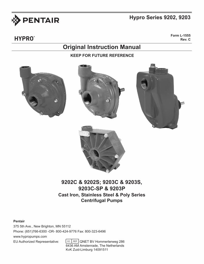
Hypro Series 9202, 9203
Form L-1555 Rev. C
Original Instruction Manual
9202C & 9202S; 9203C & 9203S, 9203C-SP & 9203P
Cast Iron, Stainless Steel & Poly Series Centrifugal Pumps
- 2 -
ContentsEU Language .........................................................................................................................................................................3
Purpose of Manual....................................................................................................................................................4
Lifting, Transport, and Intermediate Storage...............................................................................................................10
Assembly and Installation........................................................................................................................................................11
Declaration of Incorporation.................................................................................................................................................18
EU LanguagesDO NOT attempt to install or operate your pump before reading the manual. Original copies of the manual for Hypro pumpsareprovidedinEnglish.Tofindacopyinyournativelanguage,gotowww.hypropumps.com.
Vor dem Ablesen des Handbuches versuchen Sie NICHT, Ihre Pumpe zu installieren. Originale des Handbuches furHypro-PumpenwerdenaufenglischzurVerfugunggestellt.ZueineKopieinIhrerMuttersprachefinden,zuwww.hypropumps.com zu gehen (German)
N’essayez pas d’installer votre pompe avant de lire le manuel. Des exemplaires originaux du manuel pour des pompesde Hypro sont fournis en anglais. Pour trouver une copie dans votre langue maternelle pour aller awww.hypropumps.com (French)
NON tentare di installare la vostra pompa prima di leggere il manuale. Esemplare originale del manuale per Hypropompe sono in inglese. Per trovare una copia nella vostra lingua andare a www.hypropumps.com (Italian)
NO intente instalar su bomba antes de leer el manual. Copias originales del manual para Hypro se provee de bombasen ingles. Para encontrar una copia en tu idioma nativo ir a www.hypropumps.com (Spanish)
Nao tente instalar a bomba antes de ler o manual. As copias originais dos manuais para Hypro bombas saofornecidos em Ingles. Para encontrar uma copia em sua lingua nativa ir para www.hypropumps.com (Portuguese)
Hyprocentrifugalpumpsaredesignedforcreatingandboostingpressureinfluidcircuits.Thepumpoperatesbytakinginfluidfromtheinletportafterwhichitisslungbytheimpellerandexpelledthroughtheoutletport.Constructionfeaturesinclude housings, impellers and seals which come in a variety of materials in order to be resistant to a range of chemicals. Standardmodelsofcentrifugalpumpsrotateclockwise,whenlookingatthefrontofthepump.
Intended Uses
Hyprocentrifugalpumpsareintendedforcreatingorboostingdynamicpressureinapprovedfluids.Hyprocentrifugalpumps should never be used to pump liquids above 140°F (60°C), or below 34°F (1°C). Any uses outside of those specifiedinthismanualareconsideredmisusesandareprohibited.ContactHyprotechnicalservicewithanyquestionsregardingspecificacceptableuses.
Purpose of ManualThis manual provides instructions and requirements that must be met when installing, using and maintaining the product(s)identifiedonthecover.
If the product is sold, the seller must pass this manual onto the new owner.
The following special attention notices are used to notify and advise the user of this product of procedures that may be dangerous to the user or result in damage to the product.
ATTENTIONAttention is used to notify of installation, operation, or maintenance information that is important but not safety related.
California Proposition 65 Warning --ThisproductandrelatedaccessoriescontainchemicalsknowntotheState of California to cause cancer, birth defects or other reproductive harm.
MisusesHyprocentrifugalpumpsaredesignedtooperateeffectivelywithinthespecifiedspeed,pressureandenvironmentalranges.Goingoutsideoftheserangeswillvoidthewarrantyandcouldcausedamagetopropertyorseriousinjuryordeath.• DO NOT runthepumpfasterthanthemaximumspecifiedspeed.• DO NOTrunthepumphigherthanthemaximumspecifiedpressure.• DO NOT run pumps when the liquid has exceeded the maximum or minimum temperature limit (see Intended Uses).• DO NOT pump non-approved liquids.• DO NOT pump water or other liquids for human consumption.• DO NOToperateanypumpundertheinfluenceofdrugsoralcohol.• DO NOT run the pump dry.
- 5 -
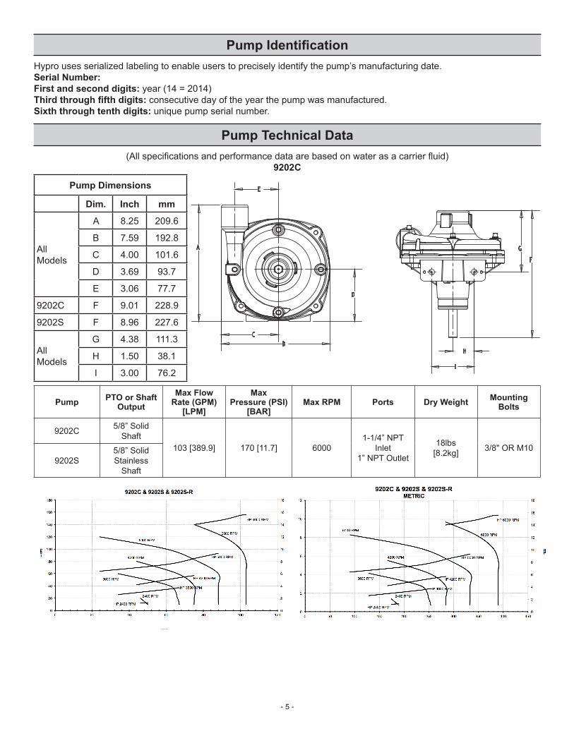
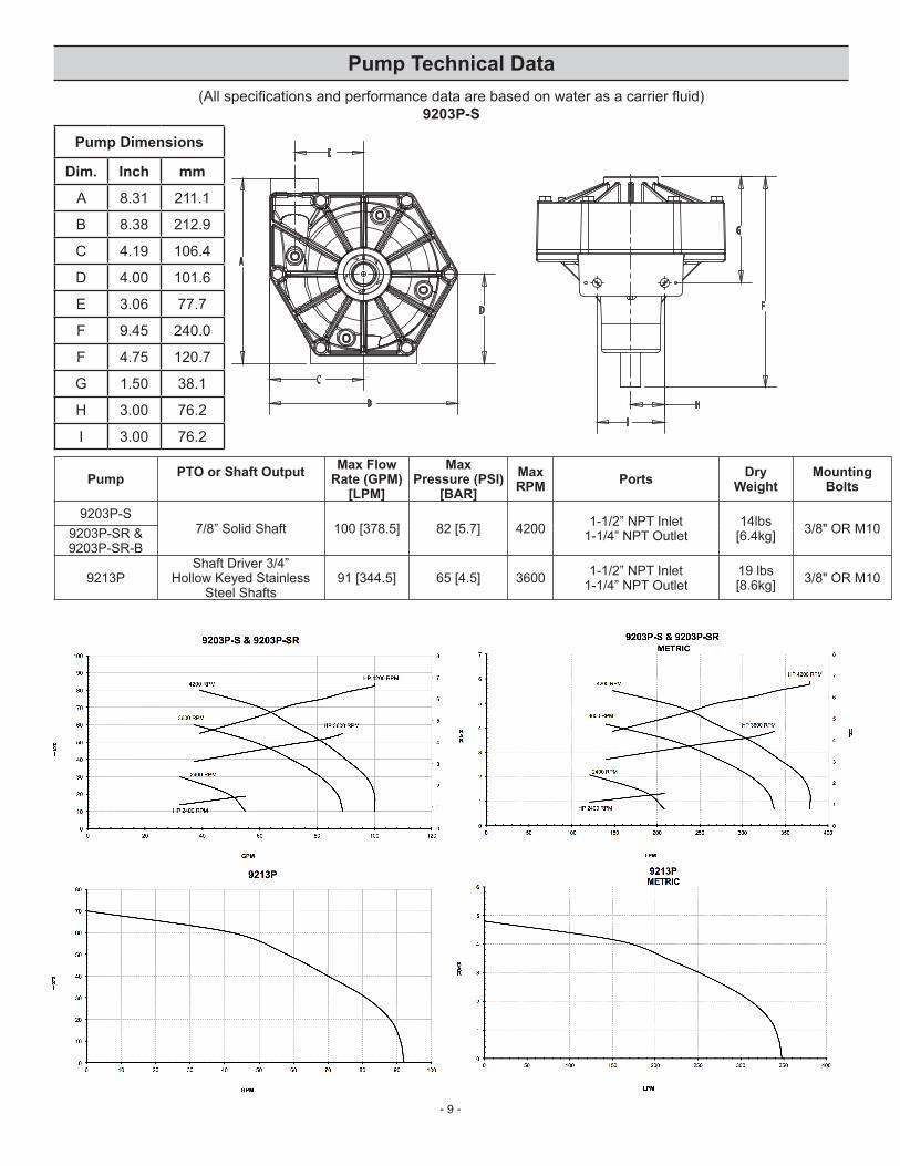
Pump IdentificationHypro uses serialized labeling to enable users to precisely identify the pump’s manufacturing date.Serial Number:First and second digits: year (14 = 2014)Third through fifth digits: consecutive day of the year the pump was manufactured.Sixth through tenth digits: unique pump serial number.
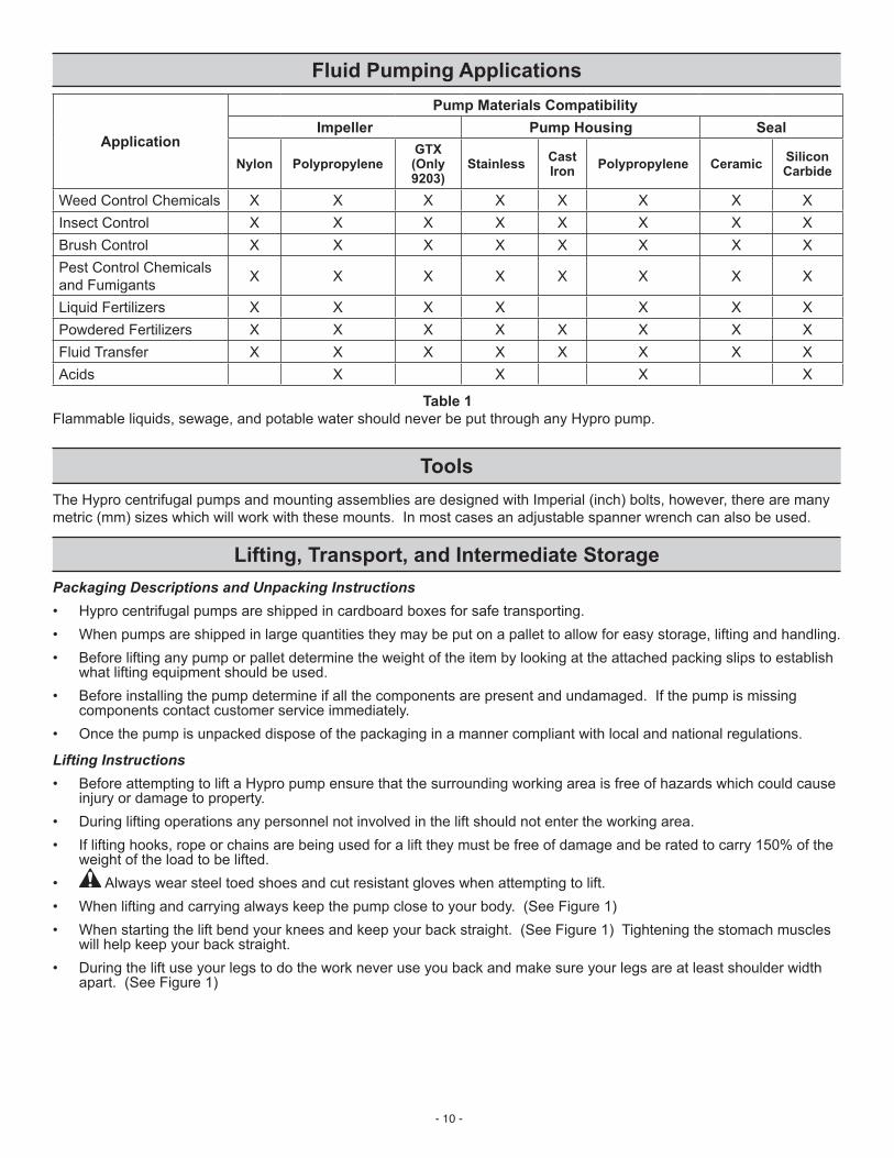
Pump Materials CompatibilityImpeller Pump Housing Seal
Nylon PolypropyleneGTX (Only 9203)
Stainless Cast Iron Polypropylene Ceramic Silicon
Carbide
Weed Control Chemicals X X X X X X X XInsect Control X X X X X X X XBrushControl X X X X X X X XPest Control Chemicals and Fumigants X X X X X X X X
Liquid Fertilizers X X X X X X XPowdered Fertilizers X X X X X X X XFluid Transfer X X X X X X X XAcids X X X X
Table 1Flammable liquids, sewage, and potable water should never be put through any Hypro pump.
ToolsThe Hypro centrifugal pumps and mounting assemblies are designed with Imperial (inch) bolts, however, there are many metric(mm)sizeswhichwillworkwiththesemounts.Inmostcasesanadjustablespannerwrenchcanalsobeused.
Lifting, Transport, and Intermediate StoragePackaging Descriptions and Unpacking Instructions• Hypro centrifugal pumps are shipped in cardboard boxes for safe transporting.• When pumps are shipped in large quantities they may be put on a pallet to allow for easy storage, lifting and handling.• Beforeliftinganypumporpalletdeterminetheweightoftheitembylookingattheattachedpackingslipstoestablish
what lifting equipment should be used.• Beforeinstallingthepumpdetermineifallthecomponentsarepresentandundamaged.Ifthepumpismissing
components contact customer service immediately.• Oncethepumpisunpackeddisposeofthepackaginginamannercompliantwithlocalandnationalregulations.
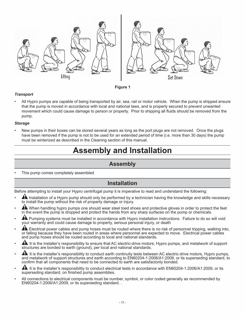
weight of the load to be lifted.• Always wear steel toed shoes and cut resistant gloves when attempting to lift. • Whenliftingandcarryingalwayskeepthepumpclosetoyourbody.(SeeFigure1)• Whenstartingtheliftbendyourkneesandkeepyourbackstraight.(SeeFigure1)Tighteningthestomachmuscles
• All Hypro pumps are capable of being transported by air, sea, rail or motor vehicle. When the pump is shipped ensure that the pump is moved in accordance with local and national laws, and is properly secured to prevent unwanted movementwhichcouldcausedamagetopersonorproperty.Priortoshippingallfluidsshouldberemovedfromthepump.
Storage
• New pumps in their boxes can be stored several years as long as the port plugs are not removed. Once the plugs have been removed if the pump is not to be used for an extended period of time (i.e. more than 30 days) the pump must be winterized as described in the Cleaning section of this manual.
toinstallthepumpwithouttheriskofpropertydamageorinjury.• When handling hypro pumps one should wear steel toed shoes and protective gloves in order to protect the feet
in the event the pump is dropped and protect the hands from any sharp surfaces on the pump or chemicals.• Pumping systems must be installed in accordance with Hypro installation instructions. Failure to do so will void
or falling because they have been routed in areas where personnel are expected to move. Electrical power cables and pump hoses should be routed according to local and national standards.
• Itistheinstaller’sresponsibilitytoensurethatACelectric-drivemotors,Hypropumps,andmetalworkofsupportstructures are bonded to earth (ground), per local and national standards.
• It is the installer’s responsibility to conduct earth continuity tests between AC electric-drive motors, Hypro pumps, andmetalworkofsupportstructuresandearthaccordingtoEN60204-1:2006/A1:2009,oritssupersedingstandard,toconfirmthatallcomponentsthatneedtobeconnectedtoeartharesatisfactorilybonded.
• All connections to electrical components must be number, symbol, or color coded generally as recommended by EN60204-1:2006/A1:2009,oritssupersedingstandard..
- 12 -
• For pumps with gas engines, the exhaust must be directed away from operators and anyone standing nearby to ensure that exhaust fumes do not enter their breathing zone.
• If a rigid plumbing system is to be used on a Hypro centrifugal pump the system must be properly aligned with the inlet and outlet ports.
• Pumps must be installed in a location where they are accessible for any necessary maintenance.• When a main electrical supply is needed to power electric drive motors installers are responsible for ensuring that
a supply disconnect device capable of isolating the machine from its electricity supply should be provided.
Standard Mounting
• InordertopreventinjuryordamagetopropertyallHypropumpsshouldbeproperlymountedtoasolidbasewherethereisnodangerofthepumpfallingorbreakingloose.AllHypropumpscomewithmountingholeswhichallowbolts to be put into the pump so it can be secured to a sturdy base. When mounting your Hypro centrifugal pump be sure to use bolts and nuts which are compatible with any chemicals that may come into contact with them as well as choosing the correct grade of bolt based on the pump weight and any expected loads. Pumps should be mounted as close to the liquid source as possible. Non self-priming pumps must be mounted below the liquid level to function properly.
Pump Plumbing
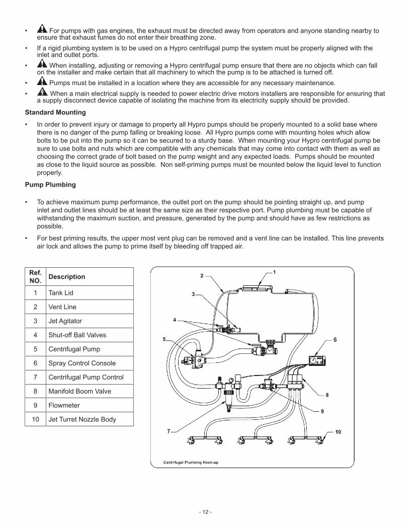
• To achieve maximum pump performance, the outlet port on the pump should be pointing straight up, and pump inlet and outlet lines should be at least the same size as their respective port. Pump plumbing must be capable of withstanding the maximum suction, and pressure, generated by the pump and should have as few restrictions as possible.
• For best priming results, the upper most vent plug can be removed and a vent line can be installed. This line prevents airlockandallowsthepumptoprimeitselfbybleedingofftrappedair.
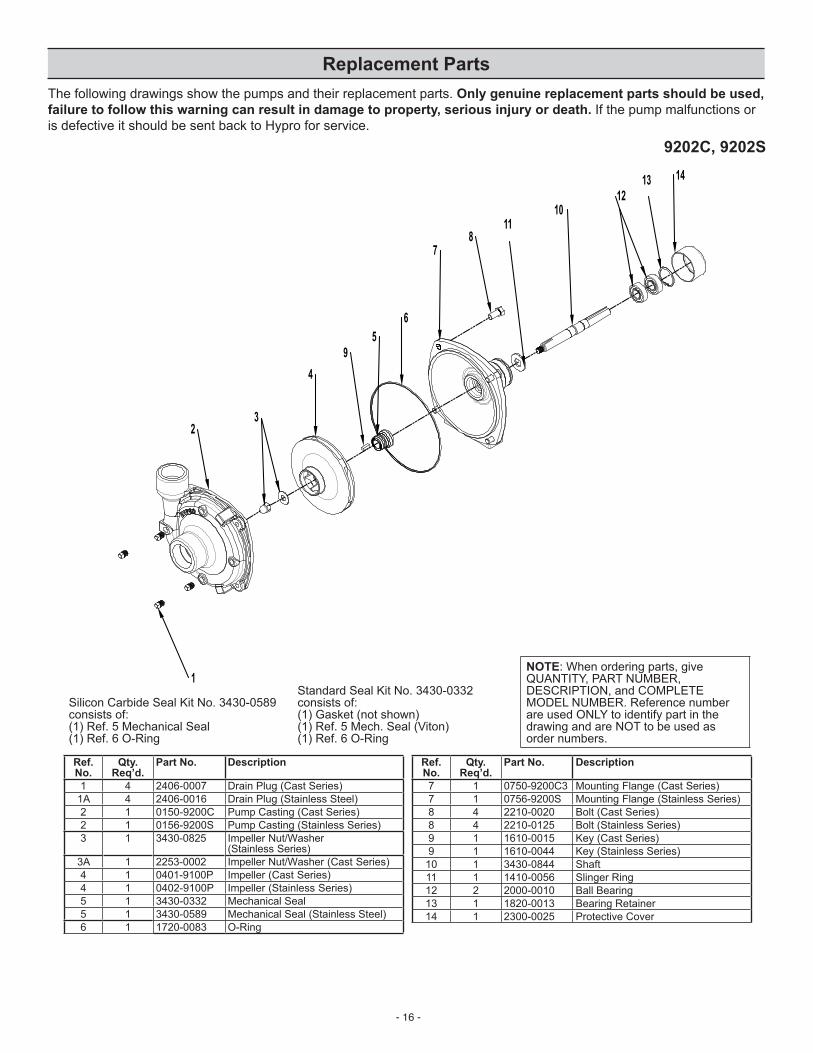
Ref. NO. Description
1 TankLid
2 Vent Line
3 Jet Agitator
4 Shut-offBallValves
5 Centrifugal Pump
6 Spray Control Console
7 Centrifugal Pump Control
8 ManifoldBoomValve
9 Flowmeter
10 JetTurretNozzleBody
- 13 -
Belt & Pulley Drive Installation Series 9200 Pedestal-Mounted Centrifugal Pumps
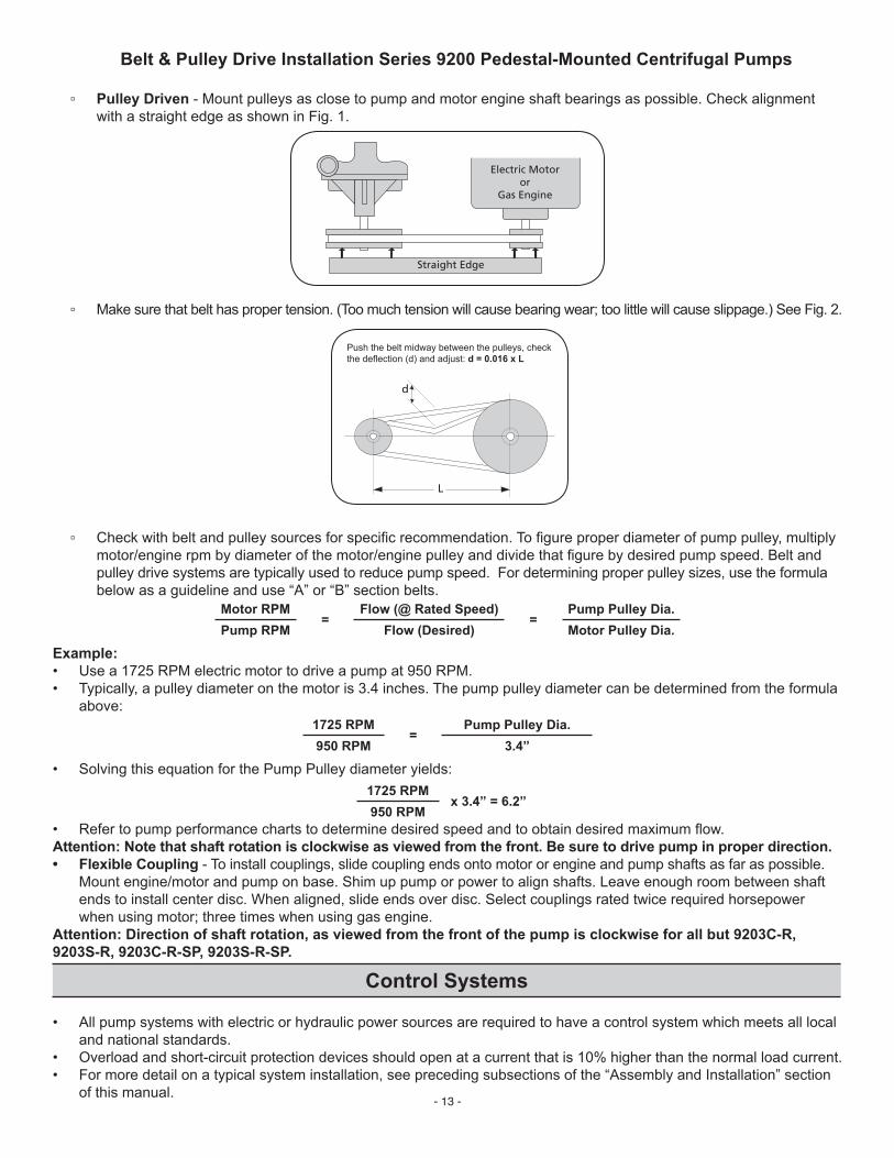
▫ Pulley Driven-Mountpulleysasclosetopumpandmotorengineshaftbearingsaspossible.Checkalignmentwith a straight edge as shown in Fig. 1.
▫ Checkwithbeltandpulleysourcesforspecificrecommendation.Tofigureproperdiameterofpumppulley,multiplymotor/enginerpmbydiameterofthemotor/enginepulleyanddividethatfigurebydesiredpumpspeed.Beltandpulley drive systems are typically used to reduce pump speed. For determining proper pulley sizes, use the formula belowasaguidelineanduse“A”or“B”sectionbelts.
Motor RPM=
Flow (@ Rated Speed)=
Pump Pulley Dia.Pump RPM Flow (Desired) Motor Pulley Dia.
Example:• Usea1725RPMelectricmotortodriveapumpat950RPM.• Typically, a pulley diameter on the motor is 3.4 inches. The pump pulley diameter can be determined from the formula
• Refertopumpperformancechartstodeterminedesiredspeedandtoobtaindesiredmaximumflow.Attention: Note that shaft rotation is clockwise as viewed from the front. Be sure to drive pump in proper direction.• Flexible Coupling - To install couplings, slide coupling ends onto motor or engine and pump shafts as far as possible.
Mountengine/motorandpumponbase.Shimuppumporpowertoalignshafts.Leaveenoughroombetweenshaftends to install center disc. When aligned, slide ends over disc. Select couplings rated twice required horsepower whenusingmotor;threetimeswhenusinggasengine.
Attention: Direction of shaft rotation, as viewed from the front of the pump is clockwise for all but 9203C-R, 9203S-R, 9203C-R-SP, 9203S-R-SP.
Control Systems
• All pump systems with electric or hydraulic power sources are required to have a control system which meets all local and national standards.
Information• When running Hypro centrifugal pumps it is essential that operators use hearing protection as the sound levels
can reach levels of 80 decibels. • When handling hypro pumps one should wear steel toed shoes and protective gloves in order to protect the feet in
the event the pump is dropped and protect the hands from any sharp surfaces on the pump or chemicals.• OnlyauthorizedoperatorshavingtheknowledgeandskillnecessarytosafelyuseaHypropump,orany
equipment the pump is connected to, may run the pump.• Whensprayingmanuallyitisrecommendedthatchemicalresistantfacemasksandclothingbeworntoprevent
anychemicalsfromcomingintocontactwiththeskinorbeinginhaled.• When spraying manually always spray upwind of yourself as long as the sprayed chemical will not drift into the
vicinity of other people.• Wheninstalling,adjustingorremovingaHyprocentrifugalpumpensurethattherearenoobjectswhichcanfallon
theinstallerandmakecertainthatallmachinerytowhichthepumpistobeattachedisturnedoff.• Hypro centrifugal pumps should only be used on tractors or tow behind spray platforms which have electrically
conductivetiresinordertoreducetheriskofelectrocution.• NeveroperateaHyprocentrifugalpumpfromoutsidewhilethereisachanceofgettingstruckbylightning.• Never leave electrical wires or plumbing components where they can be a tripping hazard or become entangled
inamovingcomponent.Ideallyelectricalcables,hoses,pipesandfittingsshouldberoutedoverhead.Intheeventelectrical wiring must be routed over the ground operators are required to use rubber ramps if they cross a gangway.
• IfusersofaHyprocentrifugalpumpareusingaPTOshaft,flexiblecouplingorbeltdrivetheyarerequiredtouseCE approved PTO shafts and guards
• Hypro centrifugal pumps should not be used if the ambient light is below 200lux.• For centrifugal pumps which use gas engines the user should always ensure the exhaust is properly attached to
theengineandisnotleaking Only use approved chemicals in your pump, for a complete list of approved chemicals see the “Fluid
Pumping Applications” section. Failure to follow this warning will void your warranty and could lead to property damage, serious injury or death.
Start-up, Operation, ShutdownBefore Starting the Pump• Ensure all unnecessary personnel are clear of the area• Forinitialsetupandtestofyoursystem,itisrecommendedtostartwithcleanwaterinsteadofchemicals,andconfirm
thesystemandplumbingconnectionsareleakfree.• Ensurethatthereisfluidinthesourcetankorsupplyline.Donotrundry.• Checklinestrainerfordebrisorclogs.Removeanyfound.• Checkallplumbingconnectionstomakesuretheyaretight.• Checkpowersourceandconnections.• Checkallvalvesandregulatorsaresettothedesiredsettingandarefunctioningproperly.• Ensure all hoses are properly positioned and are not damaged in any way.• Ensure PTO shaft shields are in place and are not loose
- 15 -
Maintenance and ServicingInformation
• All maintenance should be done when machinery is stationary and has been isolated from its energy sources. It is dangerous to perform maintenance while machinery is still connected to its power source. Machinery should be isolated from its electrical, hydraulic or gas engine power source.
• BesuretoreleaseallpressurefromthesystembeforeperforminganysortofmaintenanceonaHypropump.• DO NOT perform service or maintenance to the pump, or attached components, until the pump unit is below
109°F(43°C)• When handling Hypro pumps one should wear steel toed shoes and protective gloves in order to protect the feet
in the event the pump is dropped and protect the hands from any sharp surfaces on the pump or chemicals. If the pump is being repaired while the pump is in service eye protection should also be worn.
Any hazardous liquids should be disposed of in a manner which complies with local and national regulations, never dump fluidsontotheground.
CleaningYourpumpwilllastlongerandgivebestperformancewhenproperlytakencareof.Properpumpcaredependsontheliquidbeingpumpedandwhenthepumpwillbeusedagain.Aftereachuse,flushpumpwithaneutralizingsolutionfortheliquidjustpumped.Followwithacleanwaterrinse.Thisisespeciallyimportantforcorrosivechemicals.Itisgoodpractice to clean the pump after each use to prevent deposits from forming and damaging the pump. For infrequent use and before long periods of storage, drain pump thoroughly. Open any drain plugs, remove suction hose from liquid, and blowpumpdrywithair.Aantifreeze/rustinhibitorshouldbeinjectedintothepumpbeforebothportsarepluggedandthepumpisstored.Plugallportstokeepoutairuntilpumpisusedagain.
Maintenance, Routine Servicing, and InspectionPREVENTATIVE MAINTENANCE CHECK-LIST
Symptom Probable Cause(s) Corrective ActionPump does not prime Leakinsuctionline Checkhoseandfittingsforleaksandcorrect
Obstruction in suction line Inspect hose for obstructions and removeSuctionhosestucktotank Cutanotchor“V”inendofsuctionhoseClogged strainer Checkstrainerandcleanregularly
Low Discharge Blockedsuctionhose Inspect suction hose and repair as necessaryPump worn Repair pumpUndersized suction line See Installation
Pump will not turn Impeller plugged Inspect and clear obstruction
- 16 -
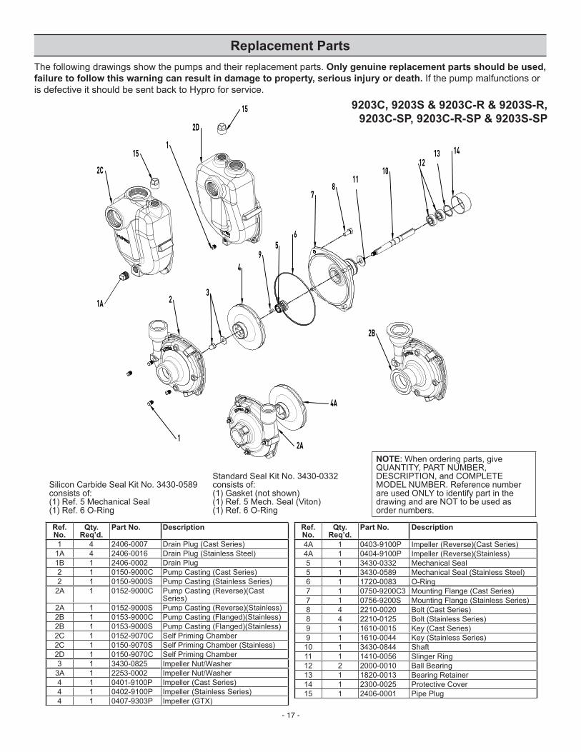
Replacement PartsThe following drawings show the pumps and their replacement parts. Only genuine replacement parts should be used, failure to follow this warning can result in damage to property, serious injury or death. If the pump malfunctions or isdefectiveitshouldbesentbacktoHyproforservice.
Standard Seal Kit No. 3430-0332 consistsof: (1)Gasket(notshown) (1)Ref.5Mech.Seal(Viton) (1) Ref. 6 O-Ring
NOTE:Whenorderingparts,giveQUANTITY,PARTNUMBER,DESCRIPTION, and COMPLETE MODELNUMBER.Referencenumberare used ONLY to identify part in the drawing and are NOT to be used as order numbers.
9202C, 9202S 1413
1210
811
7
1
49
56
23
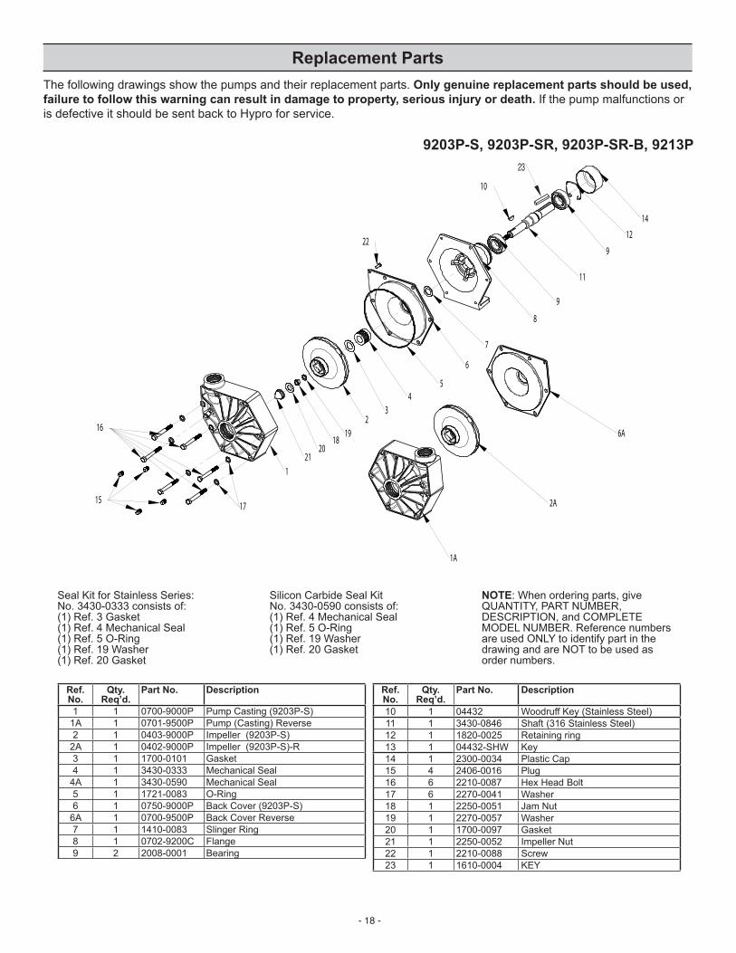
Replacement PartsThe following drawings show the pumps and their replacement parts. Only genuine replacement parts should be used, failure to follow this warning can result in damage to property, serious injury or death. If the pump malfunctions or isdefectiveitshouldbesentbacktoHyproforservice.
Standard Seal Kit No. 3430-0332 consistsof: (1)Gasket(notshown) (1)Ref.5Mech.Seal(Viton) (1) Ref. 6 O-Ring
NOTE:Whenorderingparts,giveQUANTITY,PARTNUMBER,DESCRIPTION, and COMPLETE MODELNUMBER.Referencenumberare used ONLY to identify part in the drawing and are NOT to be used as order numbers.
Replacement PartsThe following drawings show the pumps and their replacement parts. Only genuine replacement parts should be used, failure to follow this warning can result in damage to property, serious injury or death. If the pump malfunctions or isdefectiveitshouldbesentbacktoHyproforservice.
Silicon Carbide Seal Kit No.3430-0590consistsof: (1) Ref. 4 Mechanical Seal (1)Ref.5O-Ring(1) Ref. 19 Washer (1)Ref.20Gasket
NOTE:Whenorderingparts,giveQUANTITY,PARTNUMBER,DESCRIPTION, and COMPLETE MODELNUMBER.Referencenumbersare used ONLY to identify part in the drawing and are NOT to be used as order numbers.
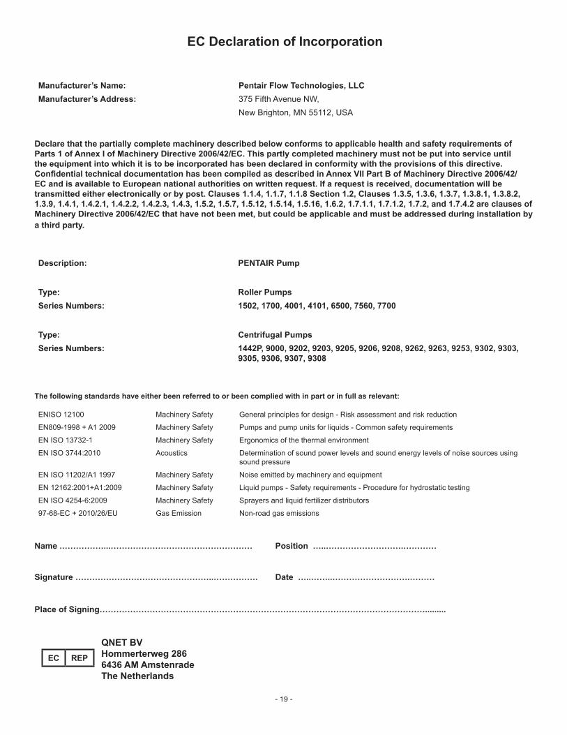
Declare that the partially complete machinery described below conforms to applicable health and safety requirements of Parts 1 of Annex I of Machinery Directive 2006/42/EC. This partly completed machinery must not be put into service until the equipment into which it is to be incorporated has been declared in conformity with the provisions of this directive. Confidential technical documentation has been compiled as described in Annex VII Part B of Machinery Directive 2006/42/EC and is available to European national authorities on written request. If a request is received, documentation will be transmitted either electronically or by post. Clauses 1.1.4, 1.1.7, 1.1.8 Section 1.2, Clauses 1.3.5, 1.3.6, 1.3.7, 1.3.8.1, 1.3.8.2, 1.3.9, 1.4.1, 1.4.2.1, 1.4.2.2, 1.4.2.3, 1.4.3, 1.5.2, 1.5.7, 1.5.12, 1.5.14, 1.5.16, 1.6.2, 1.7.1.1, 1.7.1.2, 1.7.2, and 1.7.4.2 are clauses of Machinery Directive 2006/42/EC that have not been met, but could be applicable and must be addressed during installation by a third party.
The following standards have either been referred to or been complied with in part or in full as relevant:
ENISO 12100 Machinery Safety General principles for design - Risk assessment and risk reduction
EN809-1998 + A1 2009 Machinery Safety Pumps and pump units for liquids - Common safety requirements
EN ISO 13732-1 Machinery Safety Ergonomics of the thermal environment
EN ISO 3744:2010 Acoustics Determination of sound power levels and sound energy levels of noise sources using sound pressure
EN ISO 11202/A1 1997 Machinery Safety Noise emitted by machinery and equipment
EN 12162:2001+A1:2009 Machinery Safety Liquid pumps - Safety requirements - Procedure for hydrostatic testing
EN ISO 4254-6:2009 Machinery Safety Sprayers and liquid fertilizer distributors
97-68-EC + 2010/26/EU Gas Emission Non-road gas emissions
Name .……………...…………………………………………… Position …..……………………….…………
Signature …………………………………………..……………. Date …..……..……………………….………
Place of Signing……………………………………………………………………………………………………….........
QNET BV Hommerterweg 286 6436 AM Amstenrade The Netherlands
EC REP
Limited Warranty on Hypro/SHURflo Agricultural Pumps & Accessories
Hypro/SHURflo (hereafter, “Hypro”) agricultural products arewarranted to be free of defects inmaterial andworkmanship under normal use for the time periods listed below, with proof of purchase.
-Pumps:one(1)yearfromthedateofmanufacture,orone(1)yearofuse.Thislimitedwarrantywillnot exceed two (2) years, in any event. -Accessories:ninety(90)daysofuse.
This limited warranty will not apply to products that were improperly installed, misapplied, damaged, altered, or incompatible with fluids or components not manufactured by Hypro. All warranty considerations are governed by Hypro’s written return policy.
Hypro’s obligation under this limited warranty policy is limited to the repair or replacement of the product. All returns will be tested perHypro’sfactorycriteria.Productsfoundnotdefective(underthetermsofthislimitedwarranty)aresubjecttochargespaidbythereturn-eeforthetestingandpackagingof“testedgood”non-warrantyreturns.
No credit or labor allowances will be given for products returned as defective. Warranty replacement will be shipped on a freight allowed basis. Hypro reserves the right to choose the method of transportation.
This limited warranty is in lieu of all other warranties, expressed or implied, and no other person is authorized to give any other warranty or assume obligation or liability on Hypro’s behalf. Hypro shall not be liable for any labor, damage or other expense, nor shallHyprobe liable for any indirect, incidental or consequential damagesof any kind incurredby the reasonof theuseor sale of anydefectiveproduct.ThislimitedwarrantycoversagriculturalproductsdistributedwithintheUnitedStatesofAmerica.Otherworldmarketareas should consult with the actual distributor for any deviation from this document.
Return ProceduresAllproductsmustbeflushedofanychemical(ref.OSHAsection1910.1200(d)(e)(f)(g)(h))andhazardouschemicalsmustbelabeled/tagged before being shipped* to Hypro for service or warranty consideration. Hypro reserves the right to request a Material Safety Data Sheet from the returnee foranypump/product itdeemsnecessary.Hypro reserves the right to “dispositionasscrap”products returnedwhichcontainunknownfluids.Hyproreservestherighttochargethereturneeforanyandallcostsincurredforchemicaltesting,andproperdisposalofcomponentscontainingunknownfluids.Hyprorequeststhisinordertoprotecttheenvironmentandpersonnelfromthehazardsofhandlingunknownfluids.
Contact Hypro Service Department at 800-468-3428 to receive a Return Merchandise Authorization number (RMA#). ReturnsaretobeshippedwiththeRMAnumberclearlymarkedontheoutsideofthepackage.Hyproshallnotbeliableforfreightdamageincurredduringshipping.Pleasepackageallreturnscarefully.Allproductsreturnedforwarrantyworkshouldbesentshipping charges prepaidto:
For technical or application assistance, call the Hypro Technical/Application number: 800-445-8360,orsendanemail to:[email protected]. To obtain service or warranty assistance, call the Hypro Service and Warranty number:800-468-3428;orsendafax to the Hypro Service and Warranty FAX:651-766-6618.
*Carriers, including U.S.P.S., airlines, UPS, ground freight, etc., require specific identification of any hazardous material being shipped. Failure to do so may resultinasubstantialfineand/orprisonterm.Checkwithyourshippingcompanyforspecificinstructions.