24
Trick R/C Products, LLC 938 Victoria Avenue Venice, California 90291 voice 310 301-1614 fax 310 822-7695 email [email protected] online orders www.Zagi.com

Trick R/C Products, LLC938 Victoria AvenueVenice, California 90291
voice 310 301-1614fax 310 822-7695email [email protected] orders www.Zagi.com
Safety Safety Safety Safety Safety is important even with these smallmotors. Do not run the motor until it isinstalled. See page 18.
ZZZZZ-F-F-F-F-Foam oam oam oam oam is a unique matrix that isresistant to solvents. The urethane painthowever is not. Repairs can be madewith Zagi-Lock and clear tape. Avoidoverflowing the glue onto the paintedsurfaces. Isopropyl alcohol (rubbingalcohol) or Windex can be used safely toremove residual mold release beforeapplying tape or decals. Place the decalscarefully the first time. The decaladhesive will lift the paint.
NiCad and NiMHNiCad and NiMHNiCad and NiMHNiCad and NiMHNiCad and NiMH batteries are notshipped with a charge. All batteries mustbe charged before any hookup can bedone. Charge the TX (transmitter) batteryover night with the charger in the radiocomponent box. The radio componentcharger will not charge the 8 cell 370mAh NIMH battery. It must be chargedwith a separate charger. Make sure thatthe charger is designed to charge a 9.6v8 cell MiMH battery.
Use the decal stars sparinglyUse the decal stars sparinglyUse the decal stars sparinglyUse the decal stars sparinglyUse the decal stars sparingly..... Sincemost decals and other design decora-tions are applied behind the center ofgravity, the wing can become tailheavy.The decals are better used for repairs.(See page 21)
PPPPPusher motorsusher motorsusher motorsusher motorsusher motors don’t have the advan-tage of the prop wash for cooling.Pushers instead depend on the airresulting from the forward motion of theaircraft. A heat sync employs heatconducting aluminum fins to help themotor case dissipate heat by increasingthe surface area. Lowering the operatingtemperature can extend the life of themotor. The heat sync was manufacturedto close tolarances and must be installedcorrectly to conduct properly.
The Zagi-FiXX kit contains:
Right and left wing panels
1! 370 mAh NIMH 8 cell 9.6v battery with connector
1! Zagi 5 amp electronic speed control with BEC
1! GWS EPU-3.5:1 motor and gear set with mount stick and an 8x4.3 prop
1! Battery charge lead wire
2! Pre-shaped adjustable servo-saver control rods
2! Control horns
1! Tube of Zagi-Lock CA adhesive (Ethyl Cyanoacrylate)
1! Custom decal repair set with leading edge and skid armor kit
1! Popsicle stick for antenna spooler
Optional accessories: Availablefrom Trick R/C
12 mm replacement motor without gear set
Lightweight antenna wire.
Heat sync for 12 mm motor (not included)
3 ! 370 mAh NIMH 8 cell 9.6v battery packs with connectors
6 ! 370 mAh NIMH 8 cell 9.6v battery packs with connectors
Copyright 2002 Trick R/C Products LLC1
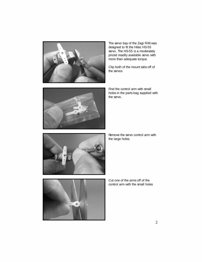
The servo bay of the Zagi FiXX wasdesigned to fit the Hitec HS-55servo. The HS-55 is a moderatelypriced readily available servo withmore than adequate torque.
Clip both of the mount tabs off ofthe servos
Find the control arm with smallholes in the parts bag supplied withthe servo.
Cut one of the arms off of thecontrol arm with the small holes
Remove the servo control arm withthe large holes.
2
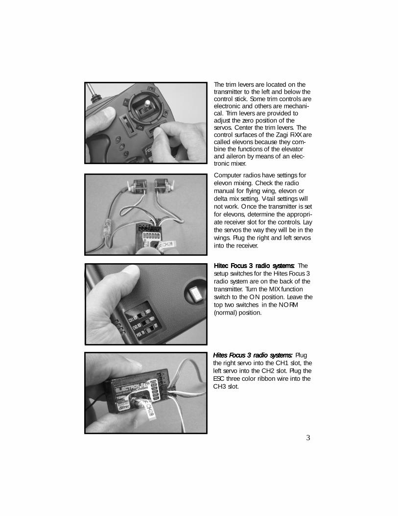
The trim levers are located on thetransmitter to the left and below thecontrol stick. Some trim controls areelectronic and others are mechani-cal. Trim levers are provided toadjust the zero position of theservos. Center the trim levers. Thecontrol surfaces of the Zagi FiXX arecalled elevons because they com-bine the functions of the elevatorand aileron by means of an elec-tronic mixer.
Hitec FHitec FHitec FHitec FHitec Focus 3 radio systems: ocus 3 radio systems: ocus 3 radio systems: ocus 3 radio systems: ocus 3 radio systems: Thesetup switches for the Hites Focus 3radio system are on the back of thetransmitter. Turn the MIX functionswitch to the ON position. Leave thetop two switches in the NORM(normal) position.
Computer radios have settings forelevon mixing. Check the radiomanual for flying wing, elevon ordelta mix setting. V-tail settings willnot work. Once the transmitter is setfor elevons, determine the appropri-ate receiver slot for the controls. Laythe servos the way they will be in thewings. Plug the right and left servosinto the receiver.
Hites FHites FHites FHites FHites Focus 3 radio systems:ocus 3 radio systems:ocus 3 radio systems:ocus 3 radio systems:ocus 3 radio systems: Plugthe right servo into the CH1 slot, theleft servo into the CH2 slot. Plug theESC three color ribbon wire into theCH3 slot.
3

The control arm should be at 90degrees to the servo in the hands offneutral position. Remove the controlarm and replace it to realign to 90degrees.
Always turn the transmitter switch tothe on position before plugging inthe airplane battery. Check thebattery condition indicator on thetransmitter to make sure that thebattery is charged.
Plug the ESC into a charged battery.The male and female JST connectorshave a polarity lock. They will onlymate in one position: RRRRRed to reded to reded to reded to reded to redand black to blackand black to blackand black to blackand black to blackand black to black.The servosshould now move when the transmit-ter stick is moved. Do not plug themotor in at this time.
When the stick is pulled back (theopposite direction to antenna) theservo control arms should moveforward. When the stick is moved tothe right, the right servo control armshould move forward and the leftservo control arm moves back.
4

Cut out the square paint thickmembrane in the corner of the servobay
Stick the servo plug through thesquare hole to the bottom of thewing.
Push the servo into the servo baywhile pulling the wire from thebottom.
Cut out the square paint-thickmembrane at the end of the wirechannel on the bottom of the wing.
5
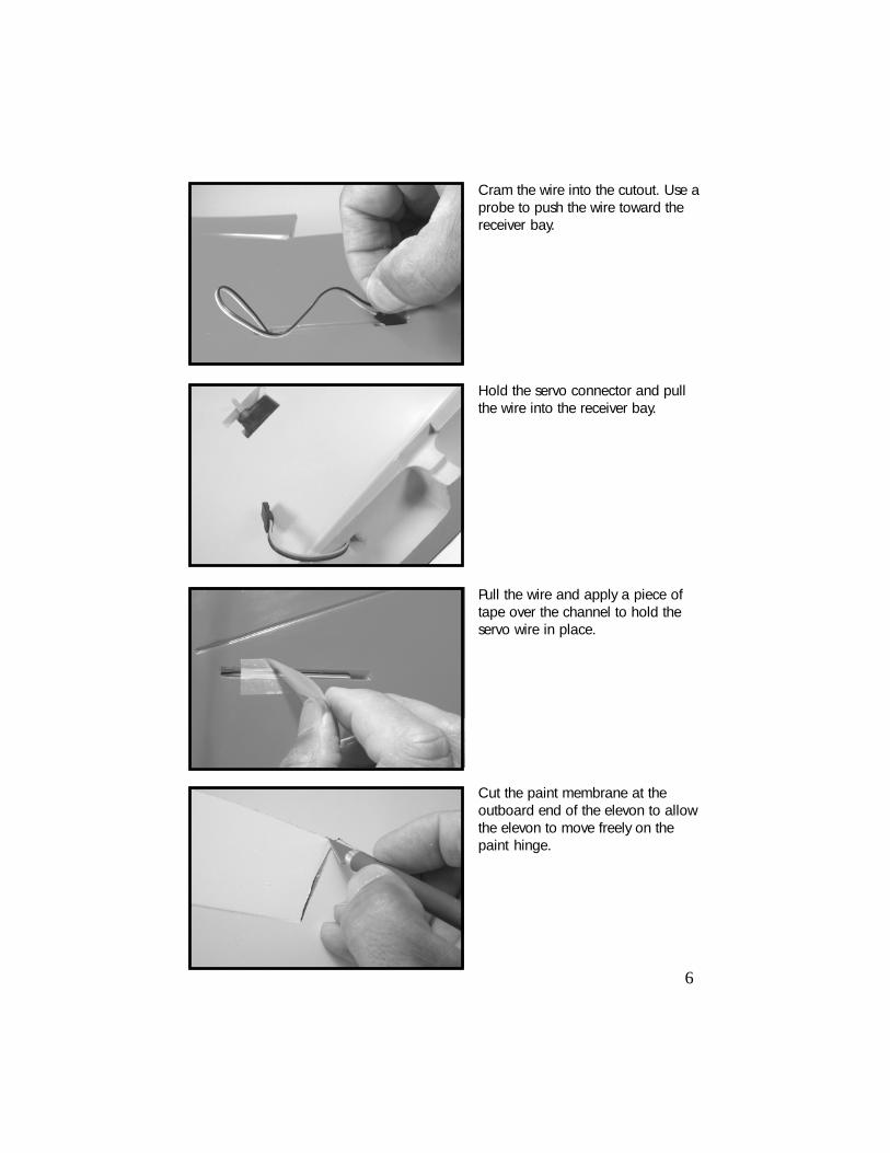
Cram the wire into the cutout. Use aprobe to push the wire toward thereceiver bay.
Pull the wire and apply a piece oftape over the channel to hold theservo wire in place.
Hold the servo connector and pullthe wire into the receiver bay.
Cut the paint membrane at theoutboard end of the elevon to allowthe elevon to move freely on thepaint hinge.
6

Trim the pushrod and hook itbetween the middle hole of the servocontrol arm and the top hole of thecontrol horn.
Squeeze a thin bead of Zagi-LockCA glue in the slot located at theinboard end of the elevon. Centerthe control horn in the slot.
Straighten the pushrod after adjust-ments are complete.
Pinch the “S” bend with pliers toadjust the center position of theelevon.
7

Locate the 2 3/4” wood motormount stick in the hardware bag.Smooth the four sides of the stick ona piece of medium sandpaper.
Round both ends of the stick bydrawing it backwords across thesandpaper.
Rounding the ends of the motormount stick will make it easier to fitin the gearbox and the motor pylon.
Push the motor mount stick into thesquare hole in the back side of thegearbox until it bottoms. The mountstick should fit snug. Sand the sidesa few more strokes if the fit is tootight.
8

9
Apply a zigzag bead of Zagi-LockCA glue to one of the flat surfacesof the center section. Make sure toapply a small bead of glue in themotor mount stick cutout on theopposite panel. Spread the glueevenly with scrap paper. Push thepanels together. Align the panelsaccording to the center bulkhead.
Locate the red Zagi-FiXX decal onthe decal sheet. The decal is usedas a glue clamp for the motor pylon.Stick it on top of one of the panels.Match the alignment marks to findthe centerline.
The motor mount stick cutout is thesquare slot located on the motorpylon. Squeeze a bead of Zagi-Lockthe length of the slot.
Slide the motor mount stick into theslot. Make sure that the stickbottoms in the slot. Half of the motormount stick will remain to be usedas an alignment pin for wingjoining.

Locate the 1 x 10 inch clear vinyltape in the decal bag. Peel the clearbacking. Secure one inch of the tapeto the aft end of the skid.
Hold the tape securely and pull ituntil it curves to the shape of theskid. Pull and lower the curved tapeonto the full length of the skid. Pressthe tape to the contour of the skid.The vinyl tape is important to createan armor film for landing.
Apply a small amount of Zagi-LockCA to the opposite motor mountstick cutout. Match the front align-ment pin with the groove and pinchthe wing panels together at the skid.Quickly wipe any glue that squeezesout with a paper towel. Clamp withclothes pins or just hold the halvestogether a few minutes until the gluesets.
Apply a bead of Zagi-Lock CA glueto the flat surfaces above the motorwire hole. Pinch the seam togetherand pull the tape over to the otherside.
10
11
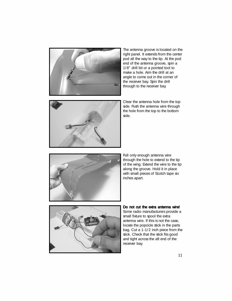
The antenna groove is located on theright panel. It extends from the centerpod all the way to the tip. At the podend of the antenna groove, spin a1/8” drill bit or a pointed tool tomake a hole. Aim the drill at anangle to come out in the corner ofthe receiver bay. Spin the drillthrough to the receiver bay.
Pull only enough antenna wirethrough the hole to extend to the tipof the wing. Extend the wire to the tipalong the groove. Hold it in placewith small pieces of Scotch tape sixinches apart.
Clear the antenna hole from the topside. Push the antenna wire throughthe hole from the top to the bottomside.
Do not cut the extra antenna wire!Do not cut the extra antenna wire!Do not cut the extra antenna wire!Do not cut the extra antenna wire!Do not cut the extra antenna wire!Some radio manufacturers provide asmall fixture to spool the extraantenna wire. If this is not the case,locate the popcicle stick in the partsbag. Cut a 1-1/2 inch piece from thestick. Check that the stick fits goodand tight across the aft end of thereceiver bay.

Do not use glue on the receiver or thebattery. Stick one of the Velcro loop sidesquares on the battery opposite thelabel. Stick one of the Velcro loop sidesquares on the receiver. If the receiverfits under the canopy on its side, put theVelcro on the side.
Spool the antenna wire around thepopcicle stick. Make an even spiralwrap around the stick being carefulnot to overlap. Hold the antennawire in place with a piece of tape.
Push the extra antenna spool acrossthe aft end of the receiver bay.Check the fit of the receiver under thecanopy when installed on its side.
Locate the Velcro squares in thehardware bag. Separate the hook fromthe loop sides. Peel the backing fromthe hook sides. Squeeze a zigzag beadof Zagi-Lock CA on the glue side of theVelcro. Glue one in the receiver bayand one in the forward most end thebattery bay.
12

13
Wipe the painted surfaces withalcohol before applying any decals.Glass cleaners like Windex workalso. Use the big blue Z decal tocover the servos
Use the large white rectangle for thecanopy hinge and lock. The logoprint or the all white rectangle maybe used. Center the decal on thecanopy
Press the canopy in place. Smooththe tape on to the wings on bothsides.
Cut one side leaving the other sideas a hinge. Use a small piece ofScotch Tape as a replaceable lock.

Locate one of the two 14 1/2 X 3/4” clear armor strips on the decalsheet. These strips are provided ascrash armor for severe head-oncrashes. In the event of such acrash the strips help to prevent thetrailingedge of the wing fromcracking or separating. Cut one ofthe strips into two equal pieces 7 1/4” long.
The clear decal armor strip worksbest when applied parallel to thetrailing edge at the prop cutout.Wipe the area with alcohol orwindex. Slip the decal under thecontrol arm. Align the decalparallel to the trailind edge andpress the square end to the base ofthe motor pylon. Press the remain-ing length to the wing. Do not try tofollow the elevon hinge line.
Measure and mark the center of theremaining armor strip on the decalsheet. Center the center line markwith the center of the wing. Alignthe armor strip with the trailing edgeof the prop cutout between theelevons.
Press the armor strip to the contourof the center pod first. Press thedecal over the full length. Airbubbles can be trapped under thearmor strip. Do not try to removethe armor strip. Poke the bubblewith a pin and chase the air bubbleout through the vent.
14

15
Remove one nut and both washers.Slide the prop onto the shaft withSlide the prop onto the shaft withSlide the prop onto the shaft withSlide the prop onto the shaft withSlide the prop onto the shaft withthe raised letters toward the motorthe raised letters toward the motorthe raised letters toward the motorthe raised letters toward the motorthe raised letters toward the motor.....Make sure that the nut mates withthe nut-shaped cutout in the prop.
Use the prop as a wrench tounscrew the nut to the end of theshaft. Leave 1/8 of an inch for thetwo washers and the nut. Slide thetwo washers against the prop. Turnthe nut on the shaft. Hold the largegear and the prop to snug the shaftnut.
Insert the motor wire into the motorwire hole in the motor pylon. Pull thewire from the receiver bay side whilepushing the motor onto the motormount stick.
Push the motor all the way onto themotor mount stick until it seats.

Plug the right and left servos into theReceiver. Plug the ESC radio wireinto the receiver. Roll the ESC wiresand stuff them next to the receiver.Push the ESC on the top with thelabel side down.
Plug the motor wire into the ESC.The polarity to the motor should bereversed so that the motor will workas a pusher. It is easy to see the redside of the motor plug beingplugged into the black side of theESC wire. DO NO DO NO DO NO DO NO DO NOT PLT PLT PLT PLT PLUG THE ESCUG THE ESCUG THE ESCUG THE ESCUG THE ESCINTINTINTINTINTO THE BAO THE BAO THE BAO THE BAO THE BATTERTTERTTERTTERTTERY AY AY AY AY AT THIS TIMET THIS TIMET THIS TIMET THIS TIMET THIS TIME.....See pages 18 for first time power-upprocedures.
The ESC has no on/off switch. Usethe battery plug as the switch.
The circuit board side of the ESCshould be visible through the canopyvent hole.
16

17
The final step is balance. The centerof gravity, (CG) is located 1/8 inchforward (toward the nose) of theservo wire channel.
If the airplane has been assembledusing this manual, the balanceshould be correct. Make sure thatthe battery is all the way forward inthe battery bay and the motor andprop are in place. Balance theairplane on your fingertips 1/8 of aninch forward of the servo wirechannel
The Zagi-FiXX will fly best with theelevons set between zero and .03”of up elevator.
The most common reason forbalance problems is over decoratingthe wings. Use the decals sparingly.Repairs can change the CG. Alwayscheck the balance after repairs. Anickel in front of the battery willoften take care of a tail heavycondition but you might need aquarter.
C/G

FFFFFirst time motor powerirst time motor powerirst time motor powerirst time motor powerirst time motor power-up-up-up-up-up. The following steps are provided for a safe first timeThe following steps are provided for a safe first timeThe following steps are provided for a safe first timeThe following steps are provided for a safe first timeThe following steps are provided for a safe first timemotor powermotor powermotor powermotor powermotor power-up. Make sure that the battery is charged. R-up. Make sure that the battery is charged. R-up. Make sure that the battery is charged. R-up. Make sure that the battery is charged. R-up. Make sure that the battery is charged. Rememberememberememberememberemember, the batter, the batter, the batter, the batter, the batter-----ies are not shipped with a charge.ies are not shipped with a charge.ies are not shipped with a charge.ies are not shipped with a charge.ies are not shipped with a charge.
CHARGE THE 370 mAh CELL ACHARGE THE 370 mAh CELL ACHARGE THE 370 mAh CELL ACHARGE THE 370 mAh CELL ACHARGE THE 370 mAh CELL AT A RAT A RAT A RAT A RAT A RATE UP TTE UP TTE UP TTE UP TTE UP TO 500 mAh ( 1/2 AMP).O 500 mAh ( 1/2 AMP).O 500 mAh ( 1/2 AMP).O 500 mAh ( 1/2 AMP).O 500 mAh ( 1/2 AMP).FOR THE LFOR THE LFOR THE LFOR THE LFOR THE LONGEST BAONGEST BAONGEST BAONGEST BAONGEST BATTERTTERTTERTTERTTERY LIFE 370 mAh WILL CHARGE THE 8 CELLY LIFE 370 mAh WILL CHARGE THE 8 CELLY LIFE 370 mAh WILL CHARGE THE 8 CELLY LIFE 370 mAh WILL CHARGE THE 8 CELLY LIFE 370 mAh WILL CHARGE THE 8 CELLBABABABABATTERTTERTTERTTERTTERY IN ONE HOUR. AY IN ONE HOUR. AY IN ONE HOUR. AY IN ONE HOUR. AY IN ONE HOUR. AT THE RISK OF A SHORT THE RISK OF A SHORT THE RISK OF A SHORT THE RISK OF A SHORT THE RISK OF A SHORTER BATER BATER BATER BATER BATTERTTERTTERTTERTTERY LIFEY LIFEY LIFEY LIFEY LIFE,,,,,SOME MODELERS REGULARLSOME MODELERS REGULARLSOME MODELERS REGULARLSOME MODELERS REGULARLSOME MODELERS REGULARLY CHARGE THEM FY CHARGE THEM FY CHARGE THEM FY CHARGE THEM FY CHARGE THEM FASTER.ASTER.ASTER.ASTER.ASTER.
NONONONONOTETETETETE: Always turn the transmitter (TX) on before connecting the battery and: Always turn the transmitter (TX) on before connecting the battery and: Always turn the transmitter (TX) on before connecting the battery and: Always turn the transmitter (TX) on before connecting the battery and: Always turn the transmitter (TX) on before connecting the battery anddisconnect the battery before turning off the TXdisconnect the battery before turning off the TXdisconnect the battery before turning off the TXdisconnect the battery before turning off the TXdisconnect the battery before turning off the TX.....
1. Make sure that the motor is securely attached to the motor mount stick.
2. Make sure that the reverse switch for the motor control stick on the transmitter is in the normal position. Not reversed!
3. Push the motor control stick on the transmitter to the full off position.
4. Push the motor control stick trim lever to the center position.
5. Turn the transmitter power on. Check the output meter for battery condition.
6. Secure the charged 8 cell battery in place with the Velcro tabs.
7. Check that the ESC signal lead is in the motor slot of the receiver.
8. Position yourself with the nose of the airplane pointed at you. Plug the battery into the electronic speed control (ESC). Make sure that the polarity is reversed on the motor side.
9. Move the motor control stick slowly upward. The motor should run faster the further up the stick is moved. The motor should turn counter clockwise when observed from the front.
18

19
PPPPPreflight check and glide testreflight check and glide testreflight check and glide testreflight check and glide testreflight check and glide test
Do a preflight check before every flight. Always turn the transmitter power on beforethe motor battery in the airplane is plugged in. Make sure that the motor controlstick is in the full down position. Make sure that the controls are working properly.Check the trim levers on the transmitter. Pull the control stick back and observe thatboth elevons move upward. Push the control stick to the right and observe the rightelevon moves up and the left elevon moves down. Hold the Zagi-FiXX securely bythe nose. Move the throttle stick to the half throttle position momentarily. The firstglide test should be done on flat land in a light breeze. Hold the Zagi-FiXX overyour head with the nose pointed straight ahead. Run slowly into the wind. Give it agentle push LEVEL AND STRAIGHT AHEAD. Do not point the nose upward. Correctthe flight path with the radio control stick. The test is successful when the Zagi-FiXXflies straight ahead with a slow sink rate to a sliding landing. If the Zagi-FiXX turnsin either direction after the launch, compensate by adding 2 or 3 clicks of trim inthe opposite direction with the trim lever below or next to the control stick. If theZagi-FiXX pitches up and immediately dives, add 2 or 3 clicks of down trim. Repeatthe glide test until the Zagi-FiXX flies straight ahead with a slow sink rate to a slidinglanding. Increase the launch speed each time to provide longer controlled flights.
FFFFFirst flightirst flightirst flightirst flightirst flight
Check the frequencies (channel number) of all pilots within visual range beforeturning on your transmitter. Turning on your transmitter with the same channelnumber as someone who is flying will certainly cause his plane to crash.
Radio controled model airplanes can cause considerable damage to someone orsomething if a collision occurs. Please exercise caution while flying. Learn moreabout safe flying at http://modelaircraft.org/. It is recommended that you joinhttp://modelaircraft.org/. It is recommended that you joinhttp://modelaircraft.org/. It is recommended that you joinhttp://modelaircraft.org/. It is recommended that you joinhttp://modelaircraft.org/. It is recommended that you jointhe Academy of Model Aeronautics (AMA) (1-800-435-9262) to providethe Academy of Model Aeronautics (AMA) (1-800-435-9262) to providethe Academy of Model Aeronautics (AMA) (1-800-435-9262) to providethe Academy of Model Aeronautics (AMA) (1-800-435-9262) to providethe Academy of Model Aeronautics (AMA) (1-800-435-9262) to provideinsurance, awareness of safe flying practices, and knowledge of whatinsurance, awareness of safe flying practices, and knowledge of whatinsurance, awareness of safe flying practices, and knowledge of whatinsurance, awareness of safe flying practices, and knowledge of whatinsurance, awareness of safe flying practices, and knowledge of what’s going’s going’s going’s going’s goingon in the modeling industryon in the modeling industryon in the modeling industryon in the modeling industryon in the modeling industry. At some flying sites it is mandatory that you be a. At some flying sites it is mandatory that you be a. At some flying sites it is mandatory that you be a. At some flying sites it is mandatory that you be a. At some flying sites it is mandatory that you be amember of the AMA.member of the AMA.member of the AMA.member of the AMA.member of the AMA.
Good luck,
JT

The Zagi-FiXX is supplied with a balanced power system. Changing the prop willchange the load on the motor ESC and the battery. The Zagi-5 ESC is rated at 5amps continuous. The Zagi-FiXX with a 370 mAh battery and the stock prop draw2.5 amps at full throttle. So if the prop diameter or pitch is increased, the loadcould exceed the range of the 5 amp ESC. This balanced system was tested withover a hundred flights. Changing the pitch or diameter burn out the motor afteronly a few flights. Using a 1000 mAh battery will burn out the GWS motor afteronly a few flights. Trial and error can get expensive. The way to choose the correctprop for an electric airplane is with the use of a watt meter. Astro Flight makes a“Wattmeter for indoor R/C models” for $55.00 from Trick R/C. This device willkeep the smoke from escaping from the speed control. Another useful tool is atachometer. Cermark makes a good tach for cheap. A simple thrust meter can bemade with a small postal scale calibrated in ounces. A test stand setup with awattmeter, a scale and a tach will take the guesswork out of balancing electriccomponents.
Battery life is determined by two main factors; charging and discharging. Both ofthese functions produce heat. Warm is okay, hot isn’t. A hot battery has either beencharged or discharged too fast. First, charging. Make sure that the charger isdesigned to charge the number of cells being charged. The best type of charger isthe peak detector type. These chargers will charge the battery to peak at a pre-selected rate then drops to a trickle. Chargers with timers will often over chargebatteries causing excessive heat. Manufacturers recommend charging batteries atthe rated capacity i.e., a 500 mAh battery should be charged for one hour at 500mAh. The exception to this is the batteries with the letter “R” at the end of thedesignation (500AR, or 2000SCR). The “R” means rapid charge and discharge.“R” cells are either very expensive or not available in small sizes. Hobbyists arenotorious battery abusers. Batteries that are not designed for rapid charge areroutinely over charged by charging and discharging them too fast. NiCad cellshave a finite number of cycles. Abuse will decrease the number of cycles. Electricflight hobbyists are willing to accept the shortened life of the batteries for perfor-mance. There are ways to cut these losses. Don’t charge at a rate more than twicethe designated capacity of the battery. Don’t charge a hot battery. Get enoughbatteries to fly one, cool one, and charge one. A way to speed up the cycle is tomake a 12 volt field battery cooler. Tape a 12 VDC muffin fan to a 6 inch length of2 inch PVC pipe. The muffin fan is available at Radio Shack or find an old com-puter power supply fan (but make sure it’s designed for 12 VDC and not 110 VAC).
Air flow
11
11
1212
6” Piece of 2” PVCplumbing pipe
BatteryMuffin fan
12 VDC20
21
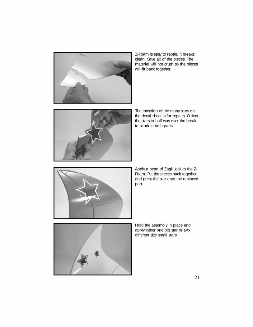
Z-Foam is easy to repair. It breaksclean. Save all of the pieces. Thematerial will not crush so the pieceswill fit back together.
Hold the assembly in place andapply either one big star or twodifferent size small stars.
Apply a bead of Zagi-Lock to the Z-Foam. Put the pieces back togetherand press the star onto the replacedpart.
The intention of the many stars onthe decal sheet is for repairs. Orientthe stars to half way over the breakto straddle both parts.

Trick R/C guarantees this kit to be free fromdefects in both workmanship and material atthe date of purchase. This does not cover anycomponents or parts damaged by use, misuseor modification. In no case shall Trick R/C’sliability exceed the original price of the pur-chased kit.
Since Trick R/C has no control over the finalassembly, no liability shall be assumed for anydamage resulting from the use by the user ofthe final user-assembled product. By the act ofusing the final user-assembled product, the useraccepts all resulting liability.
22
Zagi, Zagi Fixx, Z-Foam and Zagi-Lock CA are Trademarks of Trick R/C Products LLC


