Page 1
Document no.: 0004-0153 V09
General SpecificationOperational Envelope and Performance Guidelines
Date: 2010-10-06
Issued by: Technology R&D Class: 1
Type: T05 - General Description Page 31 of 51
Vestas Wind Systems A/S · Alsvej 21 · 8940 Randers SV · Denmark · www.vestas.com
The generator and the converter will be disconnected if:
UP UN
Voltage above 110% of nominal for 60 sec. 440 V 759 V
Voltage above 115% of nominal for 2 sec. 460 V 794 V
Voltage above 120% of nominal for 0.08 sec. 480 V 828 V
Voltage above 125% of nominal for 0.005 sec 500 V 863 V
Voltage below 90% of nominal for 60 sec. 360 V 621 V
Voltage below 85% of nominal for 11 sec. 340 V 586 V
Frequency is above [Hz] for 0.2 sec. 53 Hz
Frequency is below [Hz] for 0.2 sec. 47 Hz
Table 9-5: Generator and converter disconnecting values.
* Over the turbine lifetime, grid drop-outs are to occur at an average of no more
than 50 times a year.
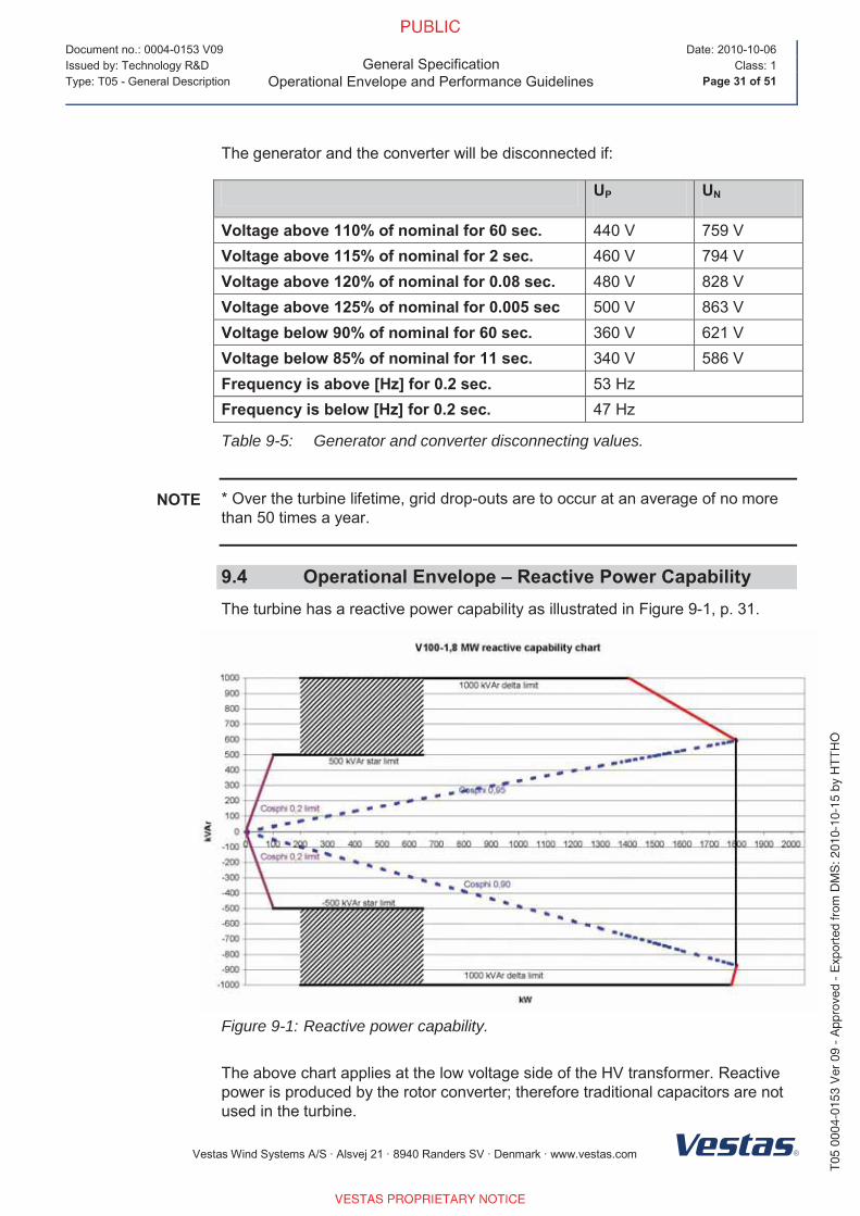
9.4 Operational Envelope – Reactive Power CapabilityThe turbine has a reactive power capability as illustrated in Figure 9-1, p. 31.
Figure 9-1: Reactive power capability.
The above chart applies at the low voltage side of the HV transformer. Reactive
power is produced by the rotor converter; therefore traditional capacitors are not
used in the turbine.
NOTE
Page 2
Document no.: 0004-0153 V09
General SpecificationOperational Envelope and Performance Guidelines
Date: 2010-10-06
Issued by: Technology R&D Class: 1
Type: T05 - General Description Page 32 of 51
Vestas Wind Systems A/S · Alsvej 21 · 8940 Randers SV · Denmark · www.vestas.com
At maximum active and reactive power, the turbine reduces either active or
reactive power depending on which type of power has priority (E.g. if reactive
power has priority, the active power is reduced.
9.5 Performance – Fault Ride ThroughThe turbine is equipped with a reinforced Vestas Converter System in order to
gain better control of the generator during grid faults. The controllers and
contactors have a UPS backup system in order to keep the turbine control
system running during grid faults.
The pitch system is optimised to keep the turbine within normal speed conditions
and the generator speed is accelerated in order to store rotational energy and be
able to resume normal power production faster after a fault and keep mechanical
stress on the turbine at a minimum.
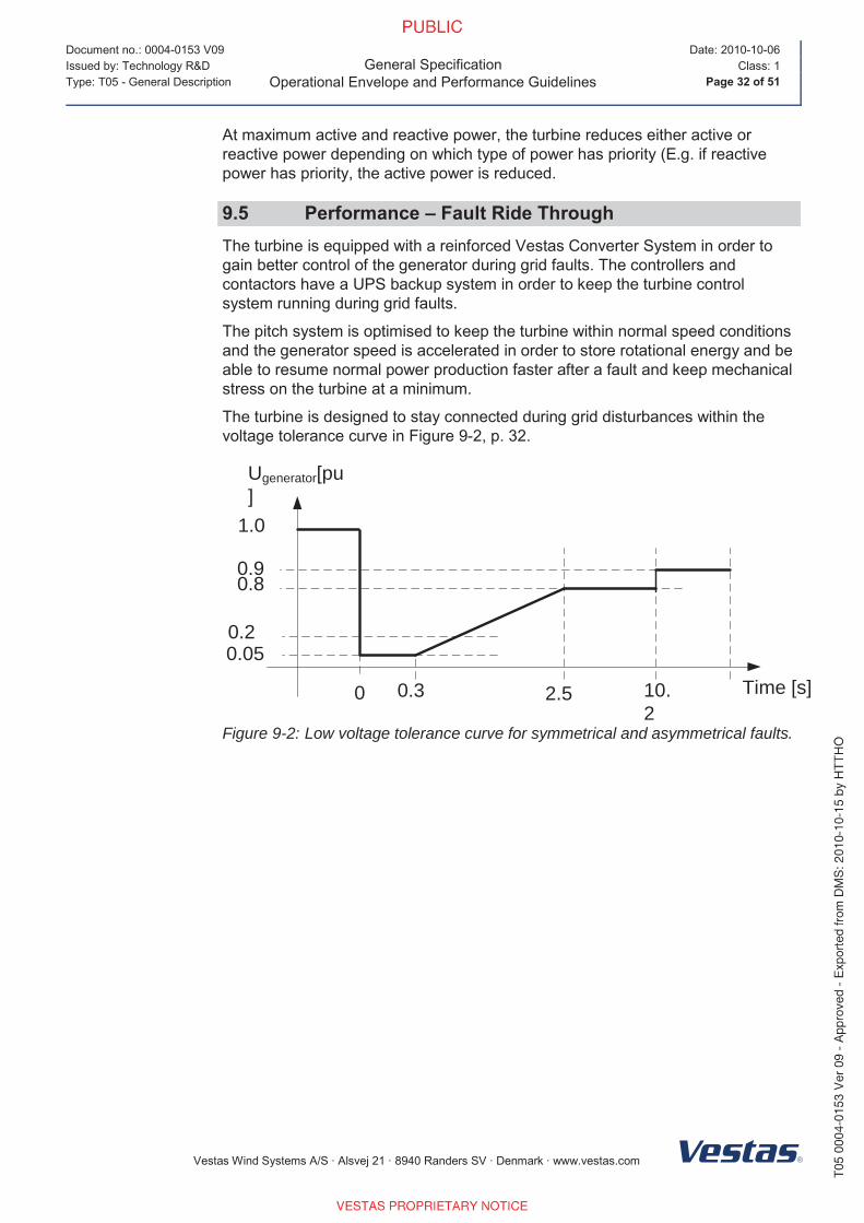
The turbine is designed to stay connected during grid disturbances within the
voltage tolerance curve in Figure 9-2, p. 32.
Ugenerator[pu]
1.0
0.2
0 2.5 Time [s]0.3
0.9
10.2
0.8
0.05
Figure 9-2: Low voltage tolerance curve for symmetrical and asymmetrical faults.
Page 3
Document no.: 0004-0153 V09
General SpecificationOperational Envelope and Performance Guidelines
Date: 2010-10-06
Issued by: Technology R&D Class: 1
Type: T05 - General Description Page 33 of 51
Vestas Wind Systems A/S · Alsvej 21 · 8940 Randers SV · Denmark · www.vestas.com
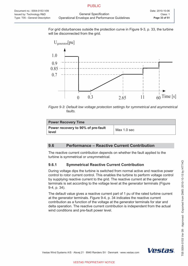
For grid disturbances outside the protection curve in Figure 9-3, p. 33, the turbine
will be disconnected from the grid.
Ugenerator[pu]
1.0
0 2.65 Time [s]0.3
0.9
11
0.70.85
60
Figure 9-3: Default low voltage protection settings for symmetrical and asymmetrical faults.
Power Recovery TimePower recovery to 90% of pre-fault level Max 1.0 sec
9.6 Performance – Reactive Current Contribution The reactive current contribution depends on whether the fault applied to the
turbine is symmetrical or unsymmetrical.
9.6.1 Symmetrical Reactive Current Contribution During voltage dips the turbine is switched from normal active and reactive power
control to rotor current control. This enables the turbine to perform voltage control
by supplying reactive current to the grid. The reactive current at the generator
terminals is set according to the voltage level at the generator terminals (Figure
9-4, p. 34).
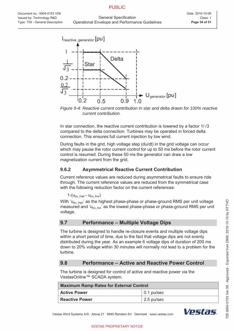
The default value gives a reactive current part of 1 pu of the rated turbine current
at the generator terminals. Figure 9-4, p. 34 indicates the reactive current
contribution as a function of the voltage at the generator terminals for star and
delta operation. The reactive current contribution is independent from the actual
wind conditions and pre-fault power level.
Page 4
Document no.: 0004-0153 V09
General SpecificationOperational Envelope and Performance Guidelines
Date: 2010-10-06
Issued by: Technology R&D Class: 1
Type: T05 - General Description Page 34 of 51
Vestas Wind Systems A/S · Alsvej 21 · 8940 Randers SV · Denmark · www.vestas.com
Figure 9-4: Reactive current contribution in star and delta drawn for 100% reactive current contribution.
In star connection, the reactive current contribution is lowered by a factor 1/√3compared to the delta connection. Turbines may be operated in forced delta
connection. This ensures full current injection by low wind.
During faults in the grid, high voltage step (du/dt) in the grid voltage can occur
which may pause the rotor current control for up to 50 ms before the rotor current
control is resumed. During these 50 ms the generator can draw a low
magnetization current from the grid.
9.6.2 Asymmetrical Reactive Current Contribution Current reference values are reduced during asymmetrical faults to ensure ride
through. The current reference values are reduced from the symmetrical case
with the following reduction factor on the current references:
1-(upu_high - upu_low)
With ’upu_high’ as the highest phase-phase or phase-ground RMS per unit voltage
measured and ’upu_low’ as the lowest phase-phase or phase-ground RMS per unit
voltage.
9.7 Performance – Multiple Voltage Dips The turbine is designed to handle re-closure events and multiple voltage dips
within a short period of time, due to the fact that voltage dips are not evenly
distributed during the year. As an example 6 voltage dips of duration of 200 ms
down to 20% voltage within 30 minutes will normally not lead to a problem for the
turbine.
9.8 Performance – Active and Reactive Power ControlThe turbine is designed for control of active and reactive power via the
VestasOnline™ SCADA system.
Maximum Ramp Rates for External ControlActive Power 0.1 pu/sec
Reactive Power 2.5 pu/sec
Page 5
Document no.: 0004-0153 V09
General SpecificationOperational Envelope and Performance Guidelines
Date: 2010-10-06
Issued by: Technology R&D Class: 1
Type: T05 - General Description Page 35 of 51
Vestas Wind Systems A/S · Alsvej 21 · 8940 Randers SV · Denmark · www.vestas.com
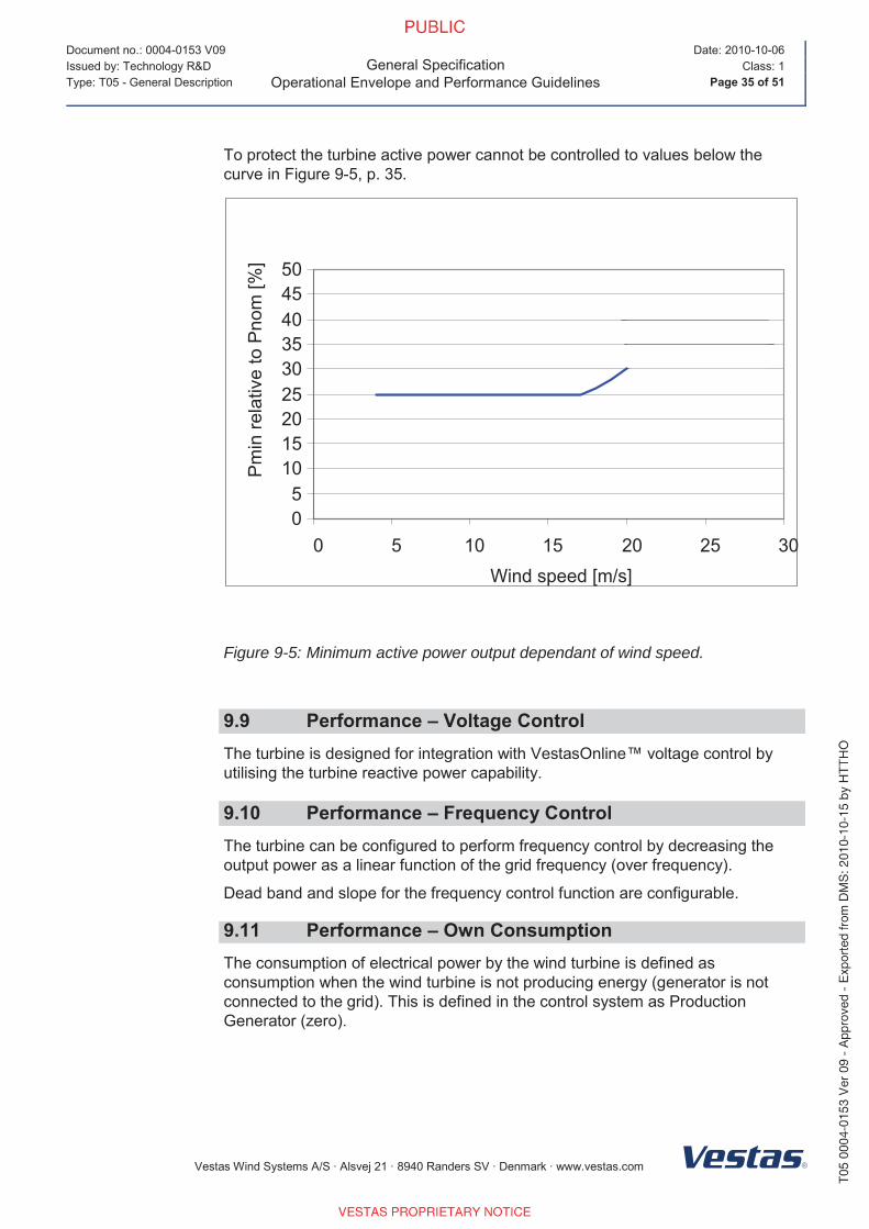
To protect the turbine active power cannot be controlled to values below the
curve in Figure 9-5, p. 35.
0
5
10
15
20
25
30
35
40
45
50
0 5 10 15 20 25 30
Wind speed [m/s]
Pm
inre
lative
toP
no
m[%
]
Figure 9-5: Minimum active power output dependant of wind speed.
9.9 Performance – Voltage ControlThe turbine is designed for integration with VestasOnline™ voltage control by
utilising the turbine reactive power capability.
9.10 Performance – Frequency ControlThe turbine can be configured to perform frequency control by decreasing the
output power as a linear function of the grid frequency (over frequency).
Dead band and slope for the frequency control function are configurable.
9.11 Performance – Own ConsumptionThe consumption of electrical power by the wind turbine is defined as
consumption when the wind turbine is not producing energy (generator is not
connected to the grid). This is defined in the control system as Production
Generator (zero).
Page 6
Document no.: 0004-0153 V09
General SpecificationOperational Envelope and Performance Guidelines
Date: 2010-10-06
Issued by: Technology R&D Class: 1
Type: T05 - General Description Page 36 of 51
Vestas Wind Systems A/S · Alsvej 21 · 8940 Randers SV · Denmark · www.vestas.com
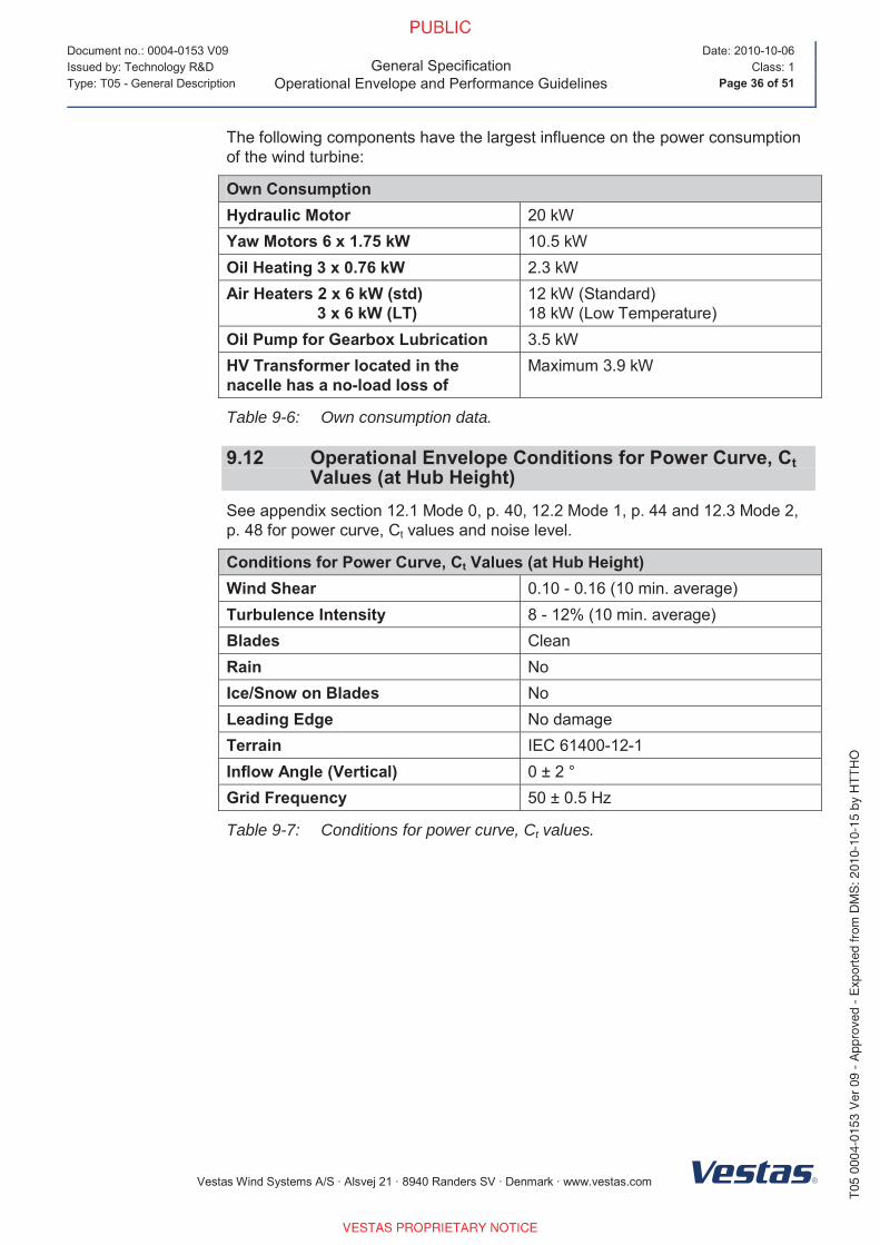
The following components have the largest influence on the power consumption
of the wind turbine:
Own ConsumptionHydraulic Motor 20 kW
Yaw Motors 6 x 1.75 kW 10.5 kW
Oil Heating 3 x 0.76 kW 2.3 kW
Air Heaters 2 x 6 kW (std) 3 x 6 kW (LT)
12 kW (Standard)
18 kW (Low Temperature)
Oil Pump for Gearbox Lubrication 3.5 kW
HV Transformer located in the nacelle has a no-load loss of
Maximum 3.9 kW
Table 9-6: Own consumption data.
9.12 Operational Envelope Conditions for Power Curve, CtValues (at Hub Height)
See appendix section 12.1 Mode 0, p. 40, 12.2 Mode 1, p. 44 and 12.3 Mode 2,
p. 48 for power curve, Ct values and noise level.
Conditions for Power Curve, Ct Values (at Hub Height)Wind Shear 0.10 - 0.16 (10 min. average)
Turbulence Intensity 8 - 12% (10 min. average)
Blades Clean
Rain No
Ice/Snow on Blades No
Leading Edge No damage
Terrain IEC 61400-12-1
Inflow Angle (Vertical) 0 ± 2 °
Grid Frequency 50 ± 0.5 Hz
Table 9-7: Conditions for power curve, Ct values.
Page 7
Document no.: 0004-0153 V09
General SpecificationDrawings
Date: 2010-10-06
Issued by: Technology R&D Class: 1
Type: T05 - General Description Page 37 of 51
Vestas Wind Systems A/S · Alsvej 21 · 8940 Randers SV · Denmark · www.vestas.com
10 Drawings
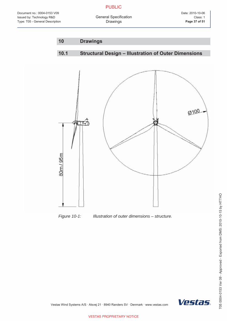
10.1 Structural Design – Illustration of Outer Dimensions
Figure 10-1: Illustration of outer dimensions – structure.
Page 8
Document no.: 0004-0153 V09
General SpecificationDrawings
Date: 2010-10-06
Issued by: Technology R&D Class: 1
Type: T05 - General Description Page 38 of 51
Vestas Wind Systems A/S · Alsvej 21 · 8940 Randers SV · Denmark · www.vestas.com
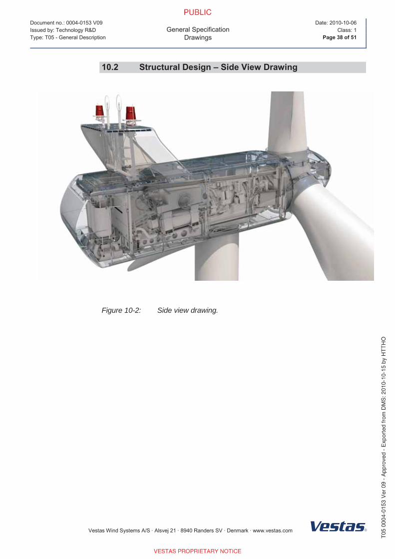
10.2 Structural Design – Side View Drawing
Figure 10-2: Side view drawing.
Page 9
Document no.: 0004-0153 V09
General SpecificationGeneral Reservations, Notes and Disclaimers
Date: 2010-10-06
Issued by: Technology R&D Class: 1
Type: T05 - General Description Page 39 of 51
Vestas Wind Systems A/S · Alsvej 21 · 8940 Randers SV · Denmark · www.vestas.com
11 General Reservations, Notes and Disclaimers
These general specifications apply to the current version of the V100 wind
turbine. Updated versions of the V100 wind turbine, which may be
manufactured in the future, may have general specifications that differ from
these general specifications. In the event that Vestas supplies an updated
version of the V100 wind turbine, Vestas will provide updated general
specifications applicable to the updated version.
Periodic operational disturbances and generator power de-rating may be
caused by combination of high winds, low voltage or high temperature.
Vestas recommends that the grid be as close to nominal as possible with little
variation in frequency.
A certain time allowance for turbine warm-up must be expected following grid
dropout and/or periods of very low ambient temperature.
The estimated power curve for the different estimated noise levels (sound
power levels) is for wind speeds at 10 minute average value at hub height
and perpendicular to the rotor plane.
All listed start/stop parameters (e. g. wind speeds and temperatures) are
equipped with hysteresis control. This can, in certain borderline situations,
result in turbine stops even though the ambient conditions are within the listed
operation parameters.
The earthing system must comply with the minimum requirements from
Vestas, and be in accordance with local and national requirements, and
codes of standards.
Lightning strikes are considered force majeure, i.e. damage caused by
lightning strikes is not warranted by Vestas.
For the avoidance of doubt, this document ‘General Specifications’ is not, and
does not contain, any guarantee, warranty and/or verification of the power
curve and noise (including, without limitation, the power curve and noise
verification method). Any guarantee, warranty and/or verification of the power
curve and noise (including, without limitation, the power curve and noise
verification method) must be agreed to separately in writing.
Page 10
Document no.: 0004-0153 V09
General SpecificationAppendices
Date: 2010-10-06
Issued by: Technology R&D Class: 1
Type: T05 - General Description Page 40 of 51
Vestas Wind Systems A/S · Alsvej 21 · 8940 Randers SV · Denmark · www.vestas.com
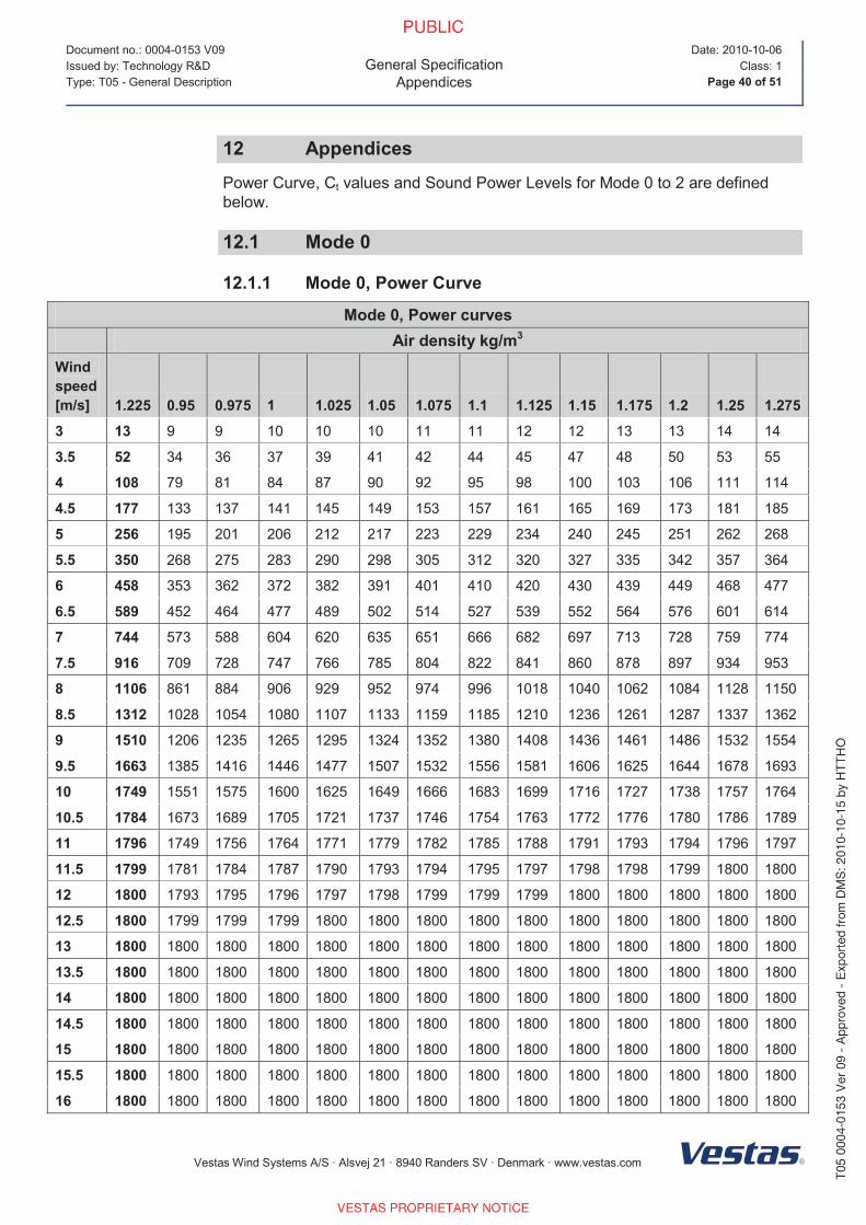
12 Appendices
Power Curve, Ct values and Sound Power Levels for Mode 0 to 2 are defined
below.
12.1 Mode 0
12.1.1 Mode 0, Power Curve
Mode 0, Power curvesAir density kg/m3
Wind speed[m/s] 1.225 0.95 0.975 1 1.025 1.05 1.075 1.1 1.125 1.15 1.175 1.2 1.25 1.275
3 13 9 9 10 10 10 11 11 12 12 13 13 14 14
3.5 52 34 36 37 39 41 42 44 45 47 48 50 53 55
4 108 79 81 84 87 90 92 95 98 100 103 106 111 114
4.5 177 133 137 141 145 149 153 157 161 165 169 173 181 185
5 256 195 201 206 212 217 223 229 234 240 245 251 262 268
5.5 350 268 275 283 290 298 305 312 320 327 335 342 357 364
6 458 353 362 372 382 391 401 410 420 430 439 449 468 477
6.5 589 452 464 477 489 502 514 527 539 552 564 576 601 614
7 744 573 588 604 620 635 651 666 682 697 713 728 759 774
7.5 916 709 728 747 766 785 804 822 841 860 878 897 934 953
8 1106 861 884 906 929 952 974 996 1018 1040 1062 1084 1128 1150
8.5 1312 1028 1054 1080 1107 1133 1159 1185 1210 1236 1261 1287 1337 1362
9 1510 1206 1235 1265 1295 1324 1352 1380 1408 1436 1461 1486 1532 1554
9.5 1663 1385 1416 1446 1477 1507 1532 1556 1581 1606 1625 1644 1678 1693
10 1749 1551 1575 1600 1625 1649 1666 1683 1699 1716 1727 1738 1757 1764
10.5 1784 1673 1689 1705 1721 1737 1746 1754 1763 1772 1776 1780 1786 1789
11 1796 1749 1756 1764 1771 1779 1782 1785 1788 1791 1793 1794 1796 1797
11.5 1799 1781 1784 1787 1790 1793 1794 1795 1797 1798 1798 1799 1800 1800
12 1800 1793 1795 1796 1797 1798 1799 1799 1799 1800 1800 1800 1800 1800
12.5 1800 1799 1799 1799 1800 1800 1800 1800 1800 1800 1800 1800 1800 1800
13 1800 1800 1800 1800 1800 1800 1800 1800 1800 1800 1800 1800 1800 1800
13.5 1800 1800 1800 1800 1800 1800 1800 1800 1800 1800 1800 1800 1800 1800
14 1800 1800 1800 1800 1800 1800 1800 1800 1800 1800 1800 1800 1800 1800
14.5 1800 1800 1800 1800 1800 1800 1800 1800 1800 1800 1800 1800 1800 1800
15 1800 1800 1800 1800 1800 1800 1800 1800 1800 1800 1800 1800 1800 1800
15.5 1800 1800 1800 1800 1800 1800 1800 1800 1800 1800 1800 1800 1800 1800
16 1800 1800 1800 1800 1800 1800 1800 1800 1800 1800 1800 1800 1800 1800
Page 11
Document no.: 0004-0153 V09
General SpecificationAppendices
Date: 2010-10-06
Issued by: Technology R&D Class: 1
Type: T05 - General Description Page 41 of 51
Vestas Wind Systems A/S · Alsvej 21 · 8940 Randers SV · Denmark · www.vestas.com
Mode 0, Power curvesAir density kg/m3
Wind speed[m/s] 1.225 0.95 0.975 1 1.025 1.05 1.075 1.1 1.125 1.15 1.175 1.2 1.25 1.275
16.5 1800 1800 1800 1800 1800 1800 1800 1800 1800 1800 1800 1800 1800 1800
17 1800 1800 1800 1800 1800 1800 1800 1800 1800 1800 1800 1800 1800 1800
17.5 1800 1800 1800 1800 1800 1800 1800 1800 1800 1800 1800 1800 1800 1800
18 1800 1800 1800 1800 1800 1800 1800 1800 1800 1800 1800 1800 1800 1800
18.5 1800 1800 1800 1800 1800 1800 1800 1800 1800 1800 1800 1800 1800 1800
19 1800 1800 1800 1800 1800 1800 1800 1800 1800 1800 1800 1800 1800 1800
19.5 1800 1800 1800 1800 1800 1800 1800 1800 1800 1800 1800 1800 1800 1800
20 1800 1800 1800 1800 1800 1800 1800 1800 1800 1800 1800 1800 1800 1800
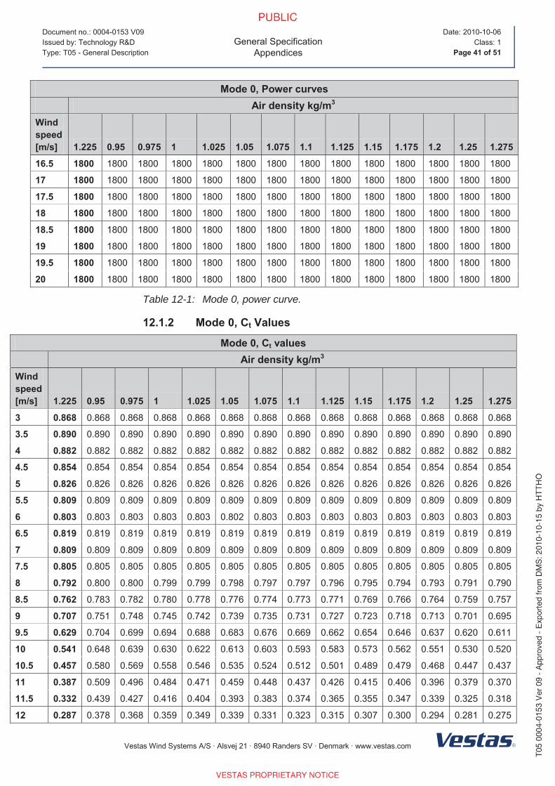
Table 12-1: Mode 0, power curve.
12.1.2 Mode 0, Ct Values
Mode 0, Ct valuesAir density kg/m3
Wind speed[m/s] 1.225 0.95 0.975 1 1.025 1.05 1.075 1.1 1.125 1.15 1.175 1.2 1.25 1.275
3 0.868 0.868 0.868 0.868 0.868 0.868 0.868 0.868 0.868 0.868 0.868 0.868 0.868 0.868
3.5 0.890 0.890 0.890 0.890 0.890 0.890 0.890 0.890 0.890 0.890 0.890 0.890 0.890 0.890
4 0.882 0.882 0.882 0.882 0.882 0.882 0.882 0.882 0.882 0.882 0.882 0.882 0.882 0.882
4.5 0.854 0.854 0.854 0.854 0.854 0.854 0.854 0.854 0.854 0.854 0.854 0.854 0.854 0.854
5 0.826 0.826 0.826 0.826 0.826 0.826 0.826 0.826 0.826 0.826 0.826 0.826 0.826 0.826
5.5 0.809 0.809 0.809 0.809 0.809 0.809 0.809 0.809 0.809 0.809 0.809 0.809 0.809 0.809
6 0.803 0.803 0.803 0.803 0.803 0.802 0.803 0.803 0.803 0.803 0.803 0.803 0.803 0.803
6.5 0.819 0.819 0.819 0.819 0.819 0.819 0.819 0.819 0.819 0.819 0.819 0.819 0.819 0.819
7 0.809 0.809 0.809 0.809 0.809 0.809 0.809 0.809 0.809 0.809 0.809 0.809 0.809 0.809
7.5 0.805 0.805 0.805 0.805 0.805 0.805 0.805 0.805 0.805 0.805 0.805 0.805 0.805 0.805
8 0.792 0.800 0.800 0.799 0.799 0.798 0.797 0.797 0.796 0.795 0.794 0.793 0.791 0.790
8.5 0.762 0.783 0.782 0.780 0.778 0.776 0.774 0.773 0.771 0.769 0.766 0.764 0.759 0.757
9 0.707 0.751 0.748 0.745 0.742 0.739 0.735 0.731 0.727 0.723 0.718 0.713 0.701 0.695
9.5 0.629 0.704 0.699 0.694 0.688 0.683 0.676 0.669 0.662 0.654 0.646 0.637 0.620 0.611
10 0.541 0.648 0.639 0.630 0.622 0.613 0.603 0.593 0.583 0.573 0.562 0.551 0.530 0.520
10.5 0.457 0.580 0.569 0.558 0.546 0.535 0.524 0.512 0.501 0.489 0.479 0.468 0.447 0.437
11 0.387 0.509 0.496 0.484 0.471 0.459 0.448 0.437 0.426 0.415 0.406 0.396 0.379 0.370
11.5 0.332 0.439 0.427 0.416 0.404 0.393 0.383 0.374 0.365 0.355 0.347 0.339 0.325 0.318
12 0.287 0.378 0.368 0.359 0.349 0.339 0.331 0.323 0.315 0.307 0.300 0.294 0.281 0.275
Page 12
Document no.: 0004-0153 V09
General SpecificationAppendices
Date: 2010-10-06
Issued by: Technology R&D Class: 1
Type: T05 - General Description Page 42 of 51
Vestas Wind Systems A/S · Alsvej 21 · 8940 Randers SV · Denmark · www.vestas.com
Mode 0, Ct valuesAir density kg/m3
Wind speed[m/s] 1.225 0.95 0.975 1 1.025 1.05 1.075 1.1 1.125 1.15 1.175 1.2 1.25 1.275
12.5 0.251 0.329 0.321 0.312 0.304 0.295 0.288 0.282 0.275 0.268 0.262 0.257 0.246 0.241
13 0.221 0.288 0.281 0.274 0.266 0.259 0.253 0.247 0.242 0.236 0.231 0.226 0.217 0.213
13.5 0.197 0.255 0.248 0.242 0.236 0.230 0.225 0.220 0.214 0.209 0.205 0.201 0.193 0.189
14 0.176 0.227 0.221 0.216 0.210 0.205 0.200 0.196 0.191 0.187 0.183 0.179 0.172 0.169
14.5 0.158 0.203 0.198 0.193 0.188 0.183 0.180 0.176 0.172 0.168 0.164 0.161 0.155 0.152
15 0.142 0.182 0.178 0.174 0.169 0.165 0.161 0.158 0.155 0.151 0.148 0.145 0.140 0.137
15.5 0.129 0.165 0.161 0.157 0.153 0.149 0.146 0.143 0.140 0.137 0.134 0.132 0.127 0.124
16 0.117 0.150 0.146 0.143 0.139 0.136 0.133 0.130 0.127 0.125 0.122 0.120 0.115 0.113
16.5 0.107 0.136 0.133 0.130 0.127 0.124 0.121 0.119 0.116 0.114 0.112 0.109 0.105 0.103
17 0.098 0.125 0.122 0.119 0.116 0.113 0.111 0.109 0.107 0.104 0.102 0.100 0.097 0.095
17.5 0.091 0.114 0.112 0.109 0.107 0.104 0.102 0.100 0.098 0.096 0.094 0.092 0.089 0.087
18 0.084 0.105 0.103 0.101 0.098 0.096 0.094 0.092 0.090 0.088 0.087 0.085 0.082 0.081
18.5 0.077 0.097 0.095 0.093 0.091 0.089 0.087 0.085 0.083 0.082 0.080 0.079 0.076 0.075
19 0.072 0.090 0.088 0.086 0.084 0.082 0.081 0.079 0.078 0.076 0.075 0.073 0.071 0.069
19.5 0.067 0.084 0.082 0.080 0.078 0.077 0.075 0.074 0.072 0.071 0.069 0.068 0.066 0.065
20 0.062 0.078 0.076 0.075 0.073 0.071 0.070 0.069 0.067 0.066 0.065 0.064 0.061 0.060
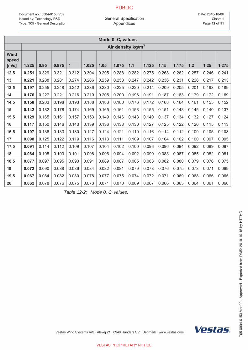
Table 12-2: Mode 0, Ct values.
Page 13
Document no.: 0004-0153 V09
General SpecificationAppendices
Date: 2010-10-06
Issued by: Technology R&D Class: 1
Type: T05 - General Description Page 43 of 51
Vestas Wind Systems A/S · Alsvej 21 · 8940 Randers SV · Denmark · www.vestas.com
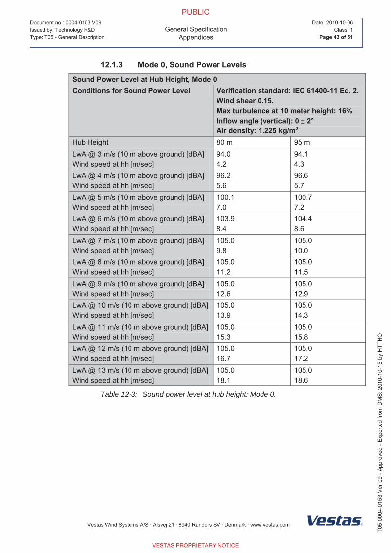
12.1.3 Mode 0, Sound Power Levels
Sound Power Level at Hub Height, Mode 0Conditions for Sound Power Level Verification standard: IEC 61400-11 Ed. 2.
Wind shear 0.15.Max turbulence at 10 meter height: 16%Inflow angle (vertical): 0 2°Air density: 1.225 kg/m3
Hub Height 80 m 95 m
LwA @ 3 m/s (10 m above ground) [dBA]
Wind speed at hh [m/sec]
94.0
4.2
94.1
4.3
LwA @ 4 m/s (10 m above ground) [dBA]
Wind speed at hh [m/sec]
96.2
5.6
96.6
5.7
LwA @ 5 m/s (10 m above ground) [dBA]
Wind speed at hh [m/sec]
100.1
7.0
100.7
7.2
LwA @ 6 m/s (10 m above ground) [dBA]
Wind speed at hh [m/sec]
103.9
8.4
104.4
8.6
LwA @ 7 m/s (10 m above ground) [dBA]
Wind speed at hh [m/sec]
105.0
9.8
105.0
10.0
LwA @ 8 m/s (10 m above ground) [dBA]
Wind speed at hh [m/sec]
105.0
11.2
105.0
11.5
LwA @ 9 m/s (10 m above ground) [dBA]
Wind speed at hh [m/sec]
105.0
12.6
105.0
12.9
LwA @ 10 m/s (10 m above ground) [dBA]
Wind speed at hh [m/sec]
105.0
13.9
105.0
14.3
LwA @ 11 m/s (10 m above ground) [dBA]
Wind speed at hh [m/sec]
105.0
15.3
105.0
15.8
LwA @ 12 m/s (10 m above ground) [dBA]
Wind speed at hh [m/sec]
105.0
16.7
105.0
17.2
LwA @ 13 m/s (10 m above ground) [dBA]
Wind speed at hh [m/sec]
105.0
18.1
105.0
18.6
Table 12-3: Sound power level at hub height: Mode 0.
Page 14
Document no.: 0004-0153 V09
General SpecificationAppendices
Date: 2010-10-06
Issued by: Technology R&D Class: 1
Type: T05 - General Description Page 44 of 51
Vestas Wind Systems A/S · Alsvej 21 · 8940 Randers SV · Denmark · www.vestas.com
12.2 Mode 1
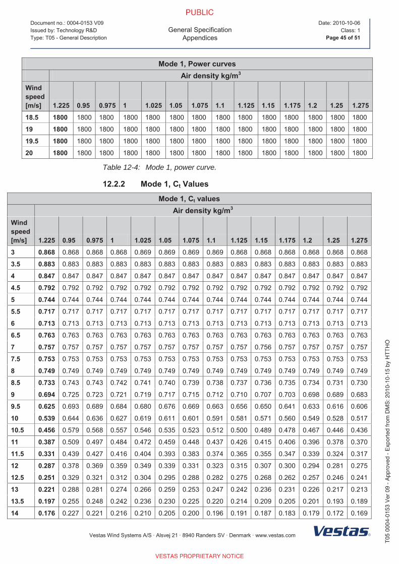
12.2.1 Mode 1, Power Curves
Mode 1, Power curvesAir density kg/m3
Wind speed[m/s] 1.225 0.95 0.975 1 1.025 1.05 1.075 1.1 1.125 1.15 1.175 1.2 1.25 1.275
3 13 9 9 10 10 10 11 11 12 12 13 13 14 14
3.5 52 34 36 37 39 41 42 44 45 47 48 50 53 55
4 108 78 81 84 87 89 92 95 98 100 103 106 111 114
4.5 174 131 135 139 143 147 151 155 159 163 167 170 178 182
5 250 190 195 201 206 212 217 223 228 233 239 244 255 261
5.5 338 259 266 273 280 288 295 302 309 317 324 331 345 353
6 445 342 351 361 370 379 389 398 407 417 426 435 454 463
6.5 582 447 459 471 484 496 508 521 533 546 558 570 595 607
7 736 567 583 598 613 629 644 660 675 691 706 721 751 767
7.5 907 702 721 740 759 777 796 814 833 852 870 889 926 944
8 1099 853 876 898 921 943 965 988 1010 1032 1054 1076 1121 1143
8.5 1307 1020 1047 1073 1099 1126 1152 1178 1204 1230 1255 1281 1332 1357
9 1509 1199 1229 1259 1289 1319 1347 1376 1405 1433 1458 1483 1531 1554
9.5 1664 1382 1413 1444 1475 1506 1531 1556 1581 1606 1625 1644 1678 1693
10 1748 1549 1574 1599 1624 1650 1666 1683 1700 1717 1727 1738 1755 1762
10.5 1783 1672 1688 1705 1721 1738 1746 1755 1763 1772 1776 1779 1785 1787
11 1796 1750 1757 1765 1772 1780 1783 1786 1789 1792 1793 1794 1796 1797
11.5 1799 1781 1784 1787 1790 1793 1795 1796 1797 1798 1798 1799 1799 1800
12 1800 1794 1795 1796 1797 1799 1799 1799 1800 1800 1800 1800 1800 1800
12.5 1800 1799 1799 1799 1800 1800 1800 1800 1800 1800 1800 1800 1800 1800
13 1800 1800 1800 1800 1800 1800 1800 1800 1800 1800 1800 1800 1800 1800
13.5 1800 1800 1800 1800 1800 1800 1800 1800 1800 1800 1800 1800 1800 1800
14 1800 1800 1800 1800 1800 1800 1800 1800 1800 1800 1800 1800 1800 1800
14.5 1800 1800 1800 1800 1800 1800 1800 1800 1800 1800 1800 1800 1800 1800
15 1800 1800 1800 1800 1800 1800 1800 1800 1800 1800 1800 1800 1800 1800
15.5 1800 1800 1800 1800 1800 1800 1800 1800 1800 1800 1800 1800 1800 1800
16 1800 1800 1800 1800 1800 1800 1800 1800 1800 1800 1800 1800 1800 1800
16.5 1800 1800 1800 1800 1800 1800 1800 1800 1800 1800 1800 1800 1800 1800
17 1800 1800 1800 1800 1800 1800 1800 1800 1800 1800 1800 1800 1800 1800
17.5 1800 1800 1800 1800 1800 1800 1800 1800 1800 1800 1800 1800 1800 1800
18 1800 1800 1800 1800 1800 1800 1800 1800 1800 1800 1800 1800 1800 1800
Page 15
Document no.: 0004-0153 V09
General SpecificationAppendices
Date: 2010-10-06
Issued by: Technology R&D Class: 1
Type: T05 - General Description Page 45 of 51
Vestas Wind Systems A/S · Alsvej 21 · 8940 Randers SV · Denmark · www.vestas.com
Mode 1, Power curvesAir density kg/m3
Wind speed[m/s] 1.225 0.95 0.975 1 1.025 1.05 1.075 1.1 1.125 1.15 1.175 1.2 1.25 1.275
18.5 1800 1800 1800 1800 1800 1800 1800 1800 1800 1800 1800 1800 1800 1800
19 1800 1800 1800 1800 1800 1800 1800 1800 1800 1800 1800 1800 1800 1800
19.5 1800 1800 1800 1800 1800 1800 1800 1800 1800 1800 1800 1800 1800 1800
20 1800 1800 1800 1800 1800 1800 1800 1800 1800 1800 1800 1800 1800 1800
Table 12-4: Mode 1, power curve.
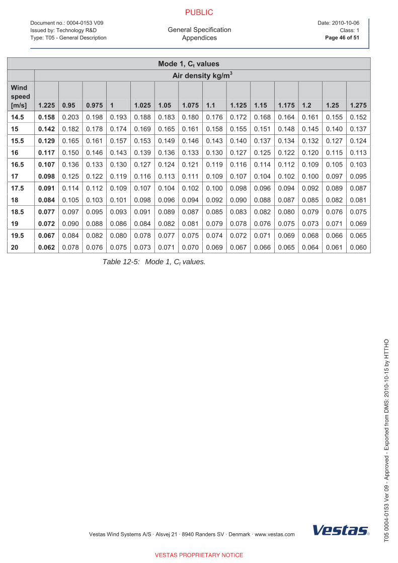
12.2.2 Mode 1, Ct Values
Mode 1, Ct valuesAir density kg/m3
Wind speed[m/s] 1.225 0.95 0.975 1 1.025 1.05 1.075 1.1 1.125 1.15 1.175 1.2 1.25 1.275
3 0.868 0.868 0.868 0.868 0.869 0.869 0.869 0.869 0.868 0.868 0.868 0.868 0.868 0.868
3.5 0.883 0.883 0.883 0.883 0.883 0.883 0.883 0.883 0.883 0.883 0.883 0.883 0.883 0.883
4 0.847 0.847 0.847 0.847 0.847 0.847 0.847 0.847 0.847 0.847 0.847 0.847 0.847 0.847
4.5 0.792 0.792 0.792 0.792 0.792 0.792 0.792 0.792 0.792 0.792 0.792 0.792 0.792 0.792
5 0.744 0.744 0.744 0.744 0.744 0.744 0.744 0.744 0.744 0.744 0.744 0.744 0.744 0.744
5.5 0.717 0.717 0.717 0.717 0.717 0.717 0.717 0.717 0.717 0.717 0.717 0.717 0.717 0.717
6 0.713 0.713 0.713 0.713 0.713 0.713 0.713 0.713 0.713 0.713 0.713 0.713 0.713 0.713
6.5 0.763 0.763 0.763 0.763 0.763 0.763 0.763 0.763 0.763 0.763 0.763 0.763 0.763 0.763
7 0.757 0.757 0.757 0.757 0.757 0.757 0.757 0.757 0.757 0.756 0.757 0.757 0.757 0.757
7.5 0.753 0.753 0.753 0.753 0.753 0.753 0.753 0.753 0.753 0.753 0.753 0.753 0.753 0.753
8 0.749 0.749 0.749 0.749 0.749 0.749 0.749 0.749 0.749 0.749 0.749 0.749 0.749 0.749
8.5 0.733 0.743 0.743 0.742 0.741 0.740 0.739 0.738 0.737 0.736 0.735 0.734 0.731 0.730
9 0.694 0.725 0.723 0.721 0.719 0.717 0.715 0.712 0.710 0.707 0.703 0.698 0.689 0.683
9.5 0.625 0.693 0.689 0.684 0.680 0.676 0.669 0.663 0.656 0.650 0.641 0.633 0.616 0.606
10 0.539 0.644 0.636 0.627 0.619 0.611 0.601 0.591 0.581 0.571 0.560 0.549 0.528 0.517
10.5 0.456 0.579 0.568 0.557 0.546 0.535 0.523 0.512 0.500 0.489 0.478 0.467 0.446 0.436
11 0.387 0.509 0.497 0.484 0.472 0.459 0.448 0.437 0.426 0.415 0.406 0.396 0.378 0.370
11.5 0.331 0.439 0.427 0.416 0.404 0.393 0.383 0.374 0.365 0.355 0.347 0.339 0.324 0.317
12 0.287 0.378 0.369 0.359 0.349 0.339 0.331 0.323 0.315 0.307 0.300 0.294 0.281 0.275
12.5 0.251 0.329 0.321 0.312 0.304 0.295 0.288 0.282 0.275 0.268 0.262 0.257 0.246 0.241
13 0.221 0.288 0.281 0.274 0.266 0.259 0.253 0.247 0.242 0.236 0.231 0.226 0.217 0.213
13.5 0.197 0.255 0.248 0.242 0.236 0.230 0.225 0.220 0.214 0.209 0.205 0.201 0.193 0.189
14 0.176 0.227 0.221 0.216 0.210 0.205 0.200 0.196 0.191 0.187 0.183 0.179 0.172 0.169
Page 16
Document no.: 0004-0153 V09
General SpecificationAppendices
Date: 2010-10-06
Issued by: Technology R&D Class: 1
Type: T05 - General Description Page 46 of 51
Vestas Wind Systems A/S · Alsvej 21 · 8940 Randers SV · Denmark · www.vestas.com
Mode 1, Ct valuesAir density kg/m3
Wind speed[m/s] 1.225 0.95 0.975 1 1.025 1.05 1.075 1.1 1.125 1.15 1.175 1.2 1.25 1.275
14.5 0.158 0.203 0.198 0.193 0.188 0.183 0.180 0.176 0.172 0.168 0.164 0.161 0.155 0.152
15 0.142 0.182 0.178 0.174 0.169 0.165 0.161 0.158 0.155 0.151 0.148 0.145 0.140 0.137
15.5 0.129 0.165 0.161 0.157 0.153 0.149 0.146 0.143 0.140 0.137 0.134 0.132 0.127 0.124
16 0.117 0.150 0.146 0.143 0.139 0.136 0.133 0.130 0.127 0.125 0.122 0.120 0.115 0.113
16.5 0.107 0.136 0.133 0.130 0.127 0.124 0.121 0.119 0.116 0.114 0.112 0.109 0.105 0.103
17 0.098 0.125 0.122 0.119 0.116 0.113 0.111 0.109 0.107 0.104 0.102 0.100 0.097 0.095
17.5 0.091 0.114 0.112 0.109 0.107 0.104 0.102 0.100 0.098 0.096 0.094 0.092 0.089 0.087
18 0.084 0.105 0.103 0.101 0.098 0.096 0.094 0.092 0.090 0.088 0.087 0.085 0.082 0.081
18.5 0.077 0.097 0.095 0.093 0.091 0.089 0.087 0.085 0.083 0.082 0.080 0.079 0.076 0.075
19 0.072 0.090 0.088 0.086 0.084 0.082 0.081 0.079 0.078 0.076 0.075 0.073 0.071 0.069
19.5 0.067 0.084 0.082 0.080 0.078 0.077 0.075 0.074 0.072 0.071 0.069 0.068 0.066 0.065
20 0.062 0.078 0.076 0.075 0.073 0.071 0.070 0.069 0.067 0.066 0.065 0.064 0.061 0.060
Table 12-5: Mode 1, Ct values.
Page 17
Document no.: 0004-0153 V09
General SpecificationAppendices
Date: 2010-10-06
Issued by: Technology R&D Class: 1
Type: T05 - General Description Page 47 of 51
Vestas Wind Systems A/S · Alsvej 21 · 8940 Randers SV · Denmark · www.vestas.com
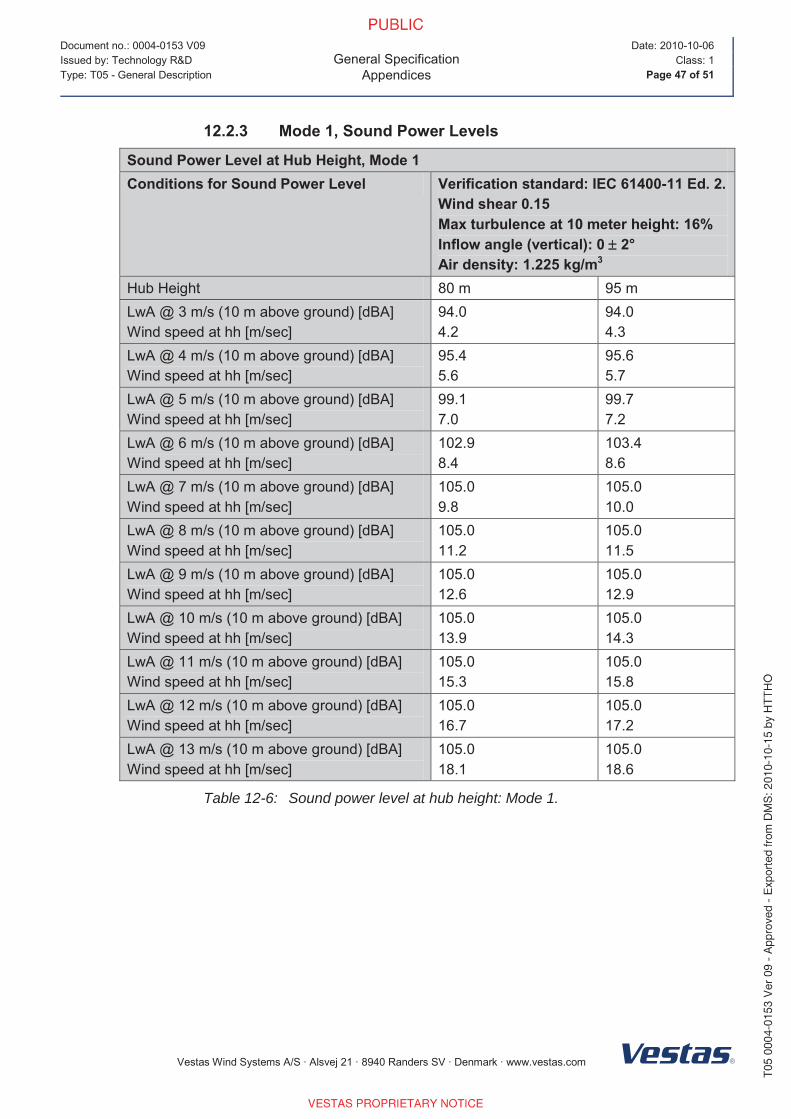
12.2.3 Mode 1, Sound Power Levels
Sound Power Level at Hub Height, Mode 1Conditions for Sound Power Level Verification standard: IEC 61400-11 Ed. 2.
Wind shear 0.15Max turbulence at 10 meter height: 16%Inflow angle (vertical): 0 2°Air density: 1.225 kg/m3
Hub Height 80 m 95 m
LwA @ 3 m/s (10 m above ground) [dBA]
Wind speed at hh [m/sec]
94.0
4.2
94.0
4.3
LwA @ 4 m/s (10 m above ground) [dBA]
Wind speed at hh [m/sec]
95.4
5.6
95.6
5.7
LwA @ 5 m/s (10 m above ground) [dBA]
Wind speed at hh [m/sec]
99.1
7.0
99.7
7.2
LwA @ 6 m/s (10 m above ground) [dBA]
Wind speed at hh [m/sec]
102.9
8.4
103.4
8.6
LwA @ 7 m/s (10 m above ground) [dBA]
Wind speed at hh [m/sec]
105.0
9.8
105.0
10.0
LwA @ 8 m/s (10 m above ground) [dBA]
Wind speed at hh [m/sec]
105.0
11.2
105.0
11.5
LwA @ 9 m/s (10 m above ground) [dBA]
Wind speed at hh [m/sec]
105.0
12.6
105.0
12.9
LwA @ 10 m/s (10 m above ground) [dBA]
Wind speed at hh [m/sec]
105.0
13.9
105.0
14.3
LwA @ 11 m/s (10 m above ground) [dBA]
Wind speed at hh [m/sec]
105.0
15.3
105.0
15.8
LwA @ 12 m/s (10 m above ground) [dBA]
Wind speed at hh [m/sec]
105.0
16.7
105.0
17.2
LwA @ 13 m/s (10 m above ground) [dBA]
Wind speed at hh [m/sec]
105.0
18.1
105.0
18.6
Table 12-6: Sound power level at hub height: Mode 1.
Page 18
Document no.: 0004-0153 V09
General SpecificationAppendices
Date: 2010-10-06
Issued by: Technology R&D Class: 1
Type: T05 - General Description Page 48 of 51
Vestas Wind Systems A/S · Alsvej 21 · 8940 Randers SV · Denmark · www.vestas.com
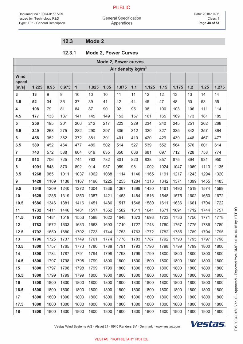
12.3 Mode 2
12.3.1 Mode 2, Power Curves
Mode 2, Power curvesAir density kg/m3
Wind speed[m/s] 1.225 0.95 0.975 1 1.025 1.05 1.075 1.1 1.125 1.15 1.175 1.2 1.25 1.275
3 13 9 9 10 10 10 11 11 12 12 13 13 14 14
3.5 52 34 36 37 39 41 42 44 45 47 48 50 53 55
4 108 79 81 84 87 90 92 95 98 100 103 106 111 114
4.5 177 133 137 141 145 149 153 157 161 165 169 173 181 185
5 256 195 201 206 212 217 223 229 234 240 245 251 262 268
5.5 349 268 275 282 290 297 305 312 320 327 335 342 357 364
6 458 352 362 372 381 391 401 410 420 429 439 448 467 477
6.5 589 452 464 477 489 502 514 527 539 552 564 576 601 614
7 743 572 588 604 619 635 650 666 681 697 712 728 758 774
7.5 913 706 725 744 763 782 801 820 838 857 875 894 931 950
8 1091 848 870 892 914 937 959 981 1002 1024 1047 1069 1113 1135
8.5 1268 985 1011 1037 1062 1088 1114 1140 1165 1191 1217 1243 1294 1320
9 1428 1109 1138 1167 1196 1225 1255 1284 1313 1342 1371 1399 1455 1483
9.5 1549 1209 1240 1272 1304 1336 1367 1399 1430 1461 1490 1519 1574 1599
10 1629 1285 1319 1353 1387 1421 1453 1484 1516 1548 1575 1602 1650 1672
10.5 1686 1346 1381 1416 1451 1486 1517 1548 1580 1611 1636 1661 1704 1722
11 1732 1411 1446 1481 1517 1552 1582 1611 1641 1671 1691 1712 1744 1757
11.5 1763 1484 1519 1553 1588 1622 1648 1673 1698 1723 1736 1750 1771 1778
12 1783 1572 1603 1633 1663 1693 1710 1727 1743 1760 1767 1775 1786 1789
12.5 1792 1659 1680 1702 1723 1744 1753 1763 1772 1782 1785 1789 1794 1795
13 1796 1725 1737 1749 1761 1774 1778 1783 1787 1792 1793 1795 1797 1798
13.5 1800 1757 1765 1773 1780 1788 1791 1793 1796 1798 1799 1799 1800 1800
14 1800 1784 1787 1791 1794 1798 1798 1799 1799 1800 1800 1800 1800 1800
14.5 1800 1797 1798 1798 1799 1800 1800 1800 1800 1800 1800 1800 1800 1800
15 1800 1797 1798 1798 1799 1799 1800 1800 1800 1800 1800 1800 1800 1800
15.5 1800 1799 1799 1799 1800 1800 1800 1800 1800 1800 1800 1800 1800 1800
16 1800 1800 1800 1800 1800 1800 1800 1800 1800 1800 1800 1800 1800 1800
16.5 1800 1800 1800 1800 1800 1800 1800 1800 1800 1800 1800 1800 1800 1800
17 1800 1800 1800 1800 1800 1800 1800 1800 1800 1800 1800 1800 1800 1800
17.5 1800 1800 1800 1800 1800 1800 1800 1800 1800 1800 1800 1800 1800 1800
18 1800 1800 1800 1800 1800 1800 1800 1800 1800 1800 1800 1800 1800 1800
Page 19
Document no.: 0004-0153 V09
General SpecificationAppendices
Date: 2010-10-06
Issued by: Technology R&D Class: 1
Type: T05 - General Description Page 49 of 51
Vestas Wind Systems A/S · Alsvej 21 · 8940 Randers SV · Denmark · www.vestas.com
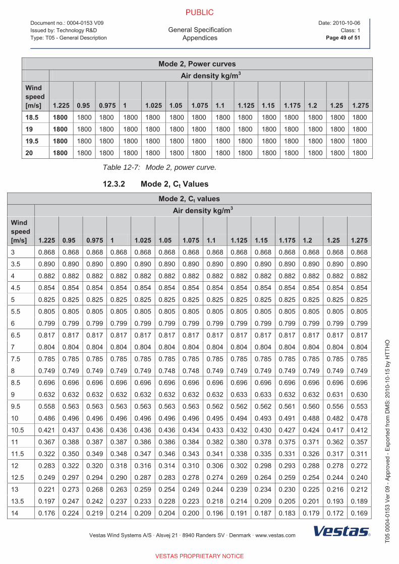
Mode 2, Power curvesAir density kg/m3
Wind speed[m/s] 1.225 0.95 0.975 1 1.025 1.05 1.075 1.1 1.125 1.15 1.175 1.2 1.25 1.275
18.5 1800 1800 1800 1800 1800 1800 1800 1800 1800 1800 1800 1800 1800 1800
19 1800 1800 1800 1800 1800 1800 1800 1800 1800 1800 1800 1800 1800 1800
19.5 1800 1800 1800 1800 1800 1800 1800 1800 1800 1800 1800 1800 1800 1800
20 1800 1800 1800 1800 1800 1800 1800 1800 1800 1800 1800 1800 1800 1800
Table 12-7: Mode 2, power curve.
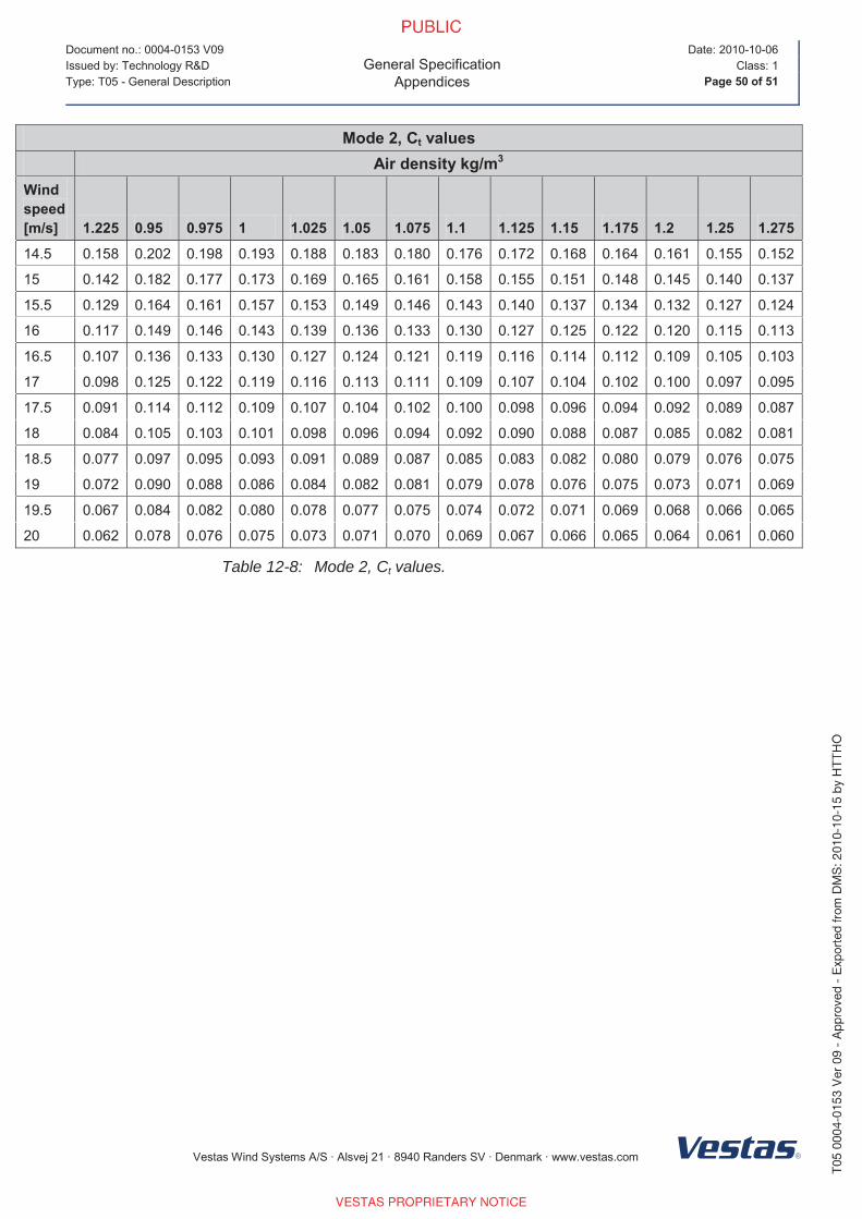
12.3.2 Mode 2, Ct Values
Mode 2, Ct valuesAir density kg/m3
Wind speed[m/s] 1.225 0.95 0.975 1 1.025 1.05 1.075 1.1 1.125 1.15 1.175 1.2 1.25 1.275
3 0.868 0.868 0.868 0.868 0.868 0.868 0.868 0.868 0.868 0.868 0.868 0.868 0.868 0.868
3.5 0.890 0.890 0.890 0.890 0.890 0.890 0.890 0.890 0.890 0.890 0.890 0.890 0.890 0.890
4 0.882 0.882 0.882 0.882 0.882 0.882 0.882 0.882 0.882 0.882 0.882 0.882 0.882 0.882
4.5 0.854 0.854 0.854 0.854 0.854 0.854 0.854 0.854 0.854 0.854 0.854 0.854 0.854 0.854
5 0.825 0.825 0.825 0.825 0.825 0.825 0.825 0.825 0.825 0.825 0.825 0.825 0.825 0.825
5.5 0.805 0.805 0.805 0.805 0.805 0.805 0.805 0.805 0.805 0.805 0.805 0.805 0.805 0.805
6 0.799 0.799 0.799 0.799 0.799 0.799 0.799 0.799 0.799 0.799 0.799 0.799 0.799 0.799
6.5 0.817 0.817 0.817 0.817 0.817 0.817 0.817 0.817 0.817 0.817 0.817 0.817 0.817 0.817
7 0.804 0.804 0.804 0.804 0.804 0.804 0.804 0.804 0.804 0.804 0.804 0.804 0.804 0.804
7.5 0.785 0.785 0.785 0.785 0.785 0.785 0.785 0.785 0.785 0.785 0.785 0.785 0.785 0.785
8 0.749 0.749 0.749 0.749 0.749 0.748 0.748 0.749 0.749 0.749 0.749 0.749 0.749 0.749
8.5 0.696 0.696 0.696 0.696 0.696 0.696 0.696 0.696 0.696 0.696 0.696 0.696 0.696 0.696
9 0.632 0.632 0.632 0.632 0.632 0.632 0.632 0.632 0.633 0.633 0.632 0.632 0.631 0.630
9.5 0.558 0.563 0.563 0.563 0.563 0.563 0.563 0.562 0.562 0.562 0.561 0.560 0.556 0.553
10 0.486 0.496 0.496 0.496 0.496 0.496 0.496 0.495 0.494 0.493 0.491 0.488 0.482 0.478
10.5 0.421 0.437 0.436 0.436 0.436 0.436 0.434 0.433 0.432 0.430 0.427 0.424 0.417 0.412
11 0.367 0.388 0.387 0.387 0.386 0.386 0.384 0.382 0.380 0.378 0.375 0.371 0.362 0.357
11.5 0.322 0.350 0.349 0.348 0.347 0.346 0.343 0.341 0.338 0.335 0.331 0.326 0.317 0.311
12 0.283 0.322 0.320 0.318 0.316 0.314 0.310 0.306 0.302 0.298 0.293 0.288 0.278 0.272
12.5 0.249 0.297 0.294 0.290 0.287 0.283 0.278 0.274 0.269 0.264 0.259 0.254 0.244 0.240
13 0.221 0.273 0.268 0.263 0.259 0.254 0.249 0.244 0.239 0.234 0.230 0.225 0.216 0.212
13.5 0.197 0.247 0.242 0.237 0.233 0.228 0.223 0.218 0.214 0.209 0.205 0.201 0.193 0.189
14 0.176 0.224 0.219 0.214 0.209 0.204 0.200 0.196 0.191 0.187 0.183 0.179 0.172 0.169
Page 20
Document no.: 0004-0153 V09
General SpecificationAppendices
Date: 2010-10-06
Issued by: Technology R&D Class: 1
Type: T05 - General Description Page 50 of 51
Vestas Wind Systems A/S · Alsvej 21 · 8940 Randers SV · Denmark · www.vestas.com
Mode 2, Ct valuesAir density kg/m3
Wind speed[m/s] 1.225 0.95 0.975 1 1.025 1.05 1.075 1.1 1.125 1.15 1.175 1.2 1.25 1.275
14.5 0.158 0.202 0.198 0.193 0.188 0.183 0.180 0.176 0.172 0.168 0.164 0.161 0.155 0.152
15 0.142 0.182 0.177 0.173 0.169 0.165 0.161 0.158 0.155 0.151 0.148 0.145 0.140 0.137
15.5 0.129 0.164 0.161 0.157 0.153 0.149 0.146 0.143 0.140 0.137 0.134 0.132 0.127 0.124
16 0.117 0.149 0.146 0.143 0.139 0.136 0.133 0.130 0.127 0.125 0.122 0.120 0.115 0.113
16.5 0.107 0.136 0.133 0.130 0.127 0.124 0.121 0.119 0.116 0.114 0.112 0.109 0.105 0.103
17 0.098 0.125 0.122 0.119 0.116 0.113 0.111 0.109 0.107 0.104 0.102 0.100 0.097 0.095
17.5 0.091 0.114 0.112 0.109 0.107 0.104 0.102 0.100 0.098 0.096 0.094 0.092 0.089 0.087
18 0.084 0.105 0.103 0.101 0.098 0.096 0.094 0.092 0.090 0.088 0.087 0.085 0.082 0.081
18.5 0.077 0.097 0.095 0.093 0.091 0.089 0.087 0.085 0.083 0.082 0.080 0.079 0.076 0.075
19 0.072 0.090 0.088 0.086 0.084 0.082 0.081 0.079 0.078 0.076 0.075 0.073 0.071 0.069
19.5 0.067 0.084 0.082 0.080 0.078 0.077 0.075 0.074 0.072 0.071 0.069 0.068 0.066 0.065
20 0.062 0.078 0.076 0.075 0.073 0.071 0.070 0.069 0.067 0.066 0.065 0.064 0.061 0.060
Table 12-8: Mode 2, Ct values.
Page 21
This is an unlicensed copy of Split Pdf
This page will be appended to every output
in unlicensed mode only.
For purchase information see our website
http://www.traction-software.co.uk/servertools/splitpdf/
Thank you,
[email protected]


![[PPT]Reactive Testing workshop - Electric Reliability … · Web viewCURL DATA USE Process for CURL Data Retrieval: Perform Reactive Capability Test Submit Test Results and CURL in](https://static.documents.pub/doc/80x56/5aebaff77f8b9ab24d8f103b/pptreactive-testing-workshop-electric-reliability-viewcurl-data-use-process.jpg)


![Real and Reactive Power Testing final.ppt [Read-Only]€¦ · Capability of a generator or generation facility is ... Microsoft PowerPoint - Real and Reactive Power Testing final.ppt](https://static.documents.pub/doc/80x56/5ad28b007f8b9a86158d40fc/real-and-reactive-power-testing-finalppt-read-only-capability-of-a-generator.jpg)


