SECTION R302 FIRE-RESISTANT CONSTRUCTION ❖ This section groups the fire-resistant construction requirements for building elements that are located between and within dwelling units and within close proximity of lot lines. This section addresses exterior wall location; townhouse separation; two-family dwellings separation; rated penetrations; garage penetrations; garage separation; under-stair protection; flame spread and smoke development; insulation; fireblocking; draft stopping required and insulation clearance from heat-producing devices. R302.1 Exterior walls. Construction, projections, openings and penetrations of exterior walls of dwellings and accessory buildings shall comply with Table R302.1(1) ; or dwellings equipped throughout with an automatic sprinkler system installed in accordance with Section P2904 shall comply with Table R302.1(2) . Exceptions: 1. Walls, projections, openings or penetrations in walls perpendicular to the line used to determine the fire separation distance. 2. Walls of dwellings and accessory structures located on the same lot. 3. Detached tool sheds and storage sheds, playhouses and similar structures exempted from permits are not required to provide wall protection based on location on the lot. Projections beyond the exterior wall shall not extend over the lot line. 4. Detached garages accessory to a dwelling located within 2 feet (610 mm) of a lot line are permitted to have roof eave projections not exceeding 4 inches (102 mm). 5. Foundation vents installed in compliance with this code are permitted. ❖ This section provides details for issues related to building location on the property, including the fire rating of exterior walls, permitted openings and projections. Tables R302.1 (1) and R302.1 (2) provide a tabular overview of the requirements of this section.
Transcript
SECTION R302FIRE-RESISTANT CONSTRUCTION
❖ This section groups the fire-resistant construction requirements for building elements that are located between and within dwelling units and within close proximity of lot lines. This section addresses exterior wall location; townhouse separation; two-family dwellings separation; rated penetrations; garage penetrations; garage separation; under-stair protection; flame spread and smoke development; insulation; fireblocking; draft stopping required and insulation clearance from heat-producing devices.
R302.1 Exterior walls.Construction, projections, openings and penetrations of exterior walls of dwellings and accessory buildings shall comply with Table R302.1(1); or dwellings equipped throughout with an automatic sprinkler system installed in accordance with Section P2904 shall comply with Table R302.1(2).
Exceptions:
1. Walls, projections, openings or penetrations in walls perpendicular to the line used to determine the fire separation distance.
2. Walls of dwellings and accessory structures located on the same lot.3. Detached tool sheds and storage sheds, playhouses and similar structures exempted from
permits are not required to provide wall protection based on location on the lot. Projections beyond the exterior wall shall not extend over the lot line.
4. Detached garages accessory to a dwelling located within 2 feet (610 mm) of a lot line are permitted to have roof eave projections not exceeding 4 inches (102 mm).
5. Foundation vents installed in compliance with this code are permitted.❖ This section provides details for issues related to building location on the property, including the fire rating of exterior walls, permitted openings and projections. Tables R302.1 (1) and R302.1 (2) provide a tabular overview of the requirements of this section.
Concerning exterior wall protection, the code assumes that an owner has no control over an adjoining property. Thus, the location of buildings on the owner’s property relative to the property line requires regulation. In addition, Section R302.6, which lists the separation requirements for garages and carports, specifically requires garages located less than 3 feet (914 mm) from a dwelling unit on the same lot to have not less than 1/2-inch (12.7 mm) gypsum board applied to the interior side of the walls. Opening protection for these walls is regulated by Section R302.5.
The property line concept is a convenient means of protecting one building from another as far as exposure is concerned. Exposure is the potential for heat to be transmitted from one building to another during a fire in the exposing building. Radiation is the primary means of heat transfer.
Table R302.1 (1) specifies the exterior wall elements, fire separation distance and fire-resistance rating for dwellings without sprinkler systems. Walls less than 5 feet (1525 mm) from the property line must be of 1-hour fire-resistant construction. The fire-resistance rating also requires the rating exposure to be for both sides. The exterior rated walls are required to be an assembly that has been tested in accordance with either ASTM E119 or UL 263. This is not intended to limit fire-resistance-rated assemblies solely to the test criteria contained in these standards. Section R104.11 still allows the building official to approve alternative fire-resistance
methodologies, such as those described in Section 703.3 of the IBC. This would still allow a builder to use acceptable engineering analysis, calculations in accordance with Section 721 of the IBC or prescriptive assemblies permitted by Section 720 of the IBC as alternatives to the standards contained within the code.
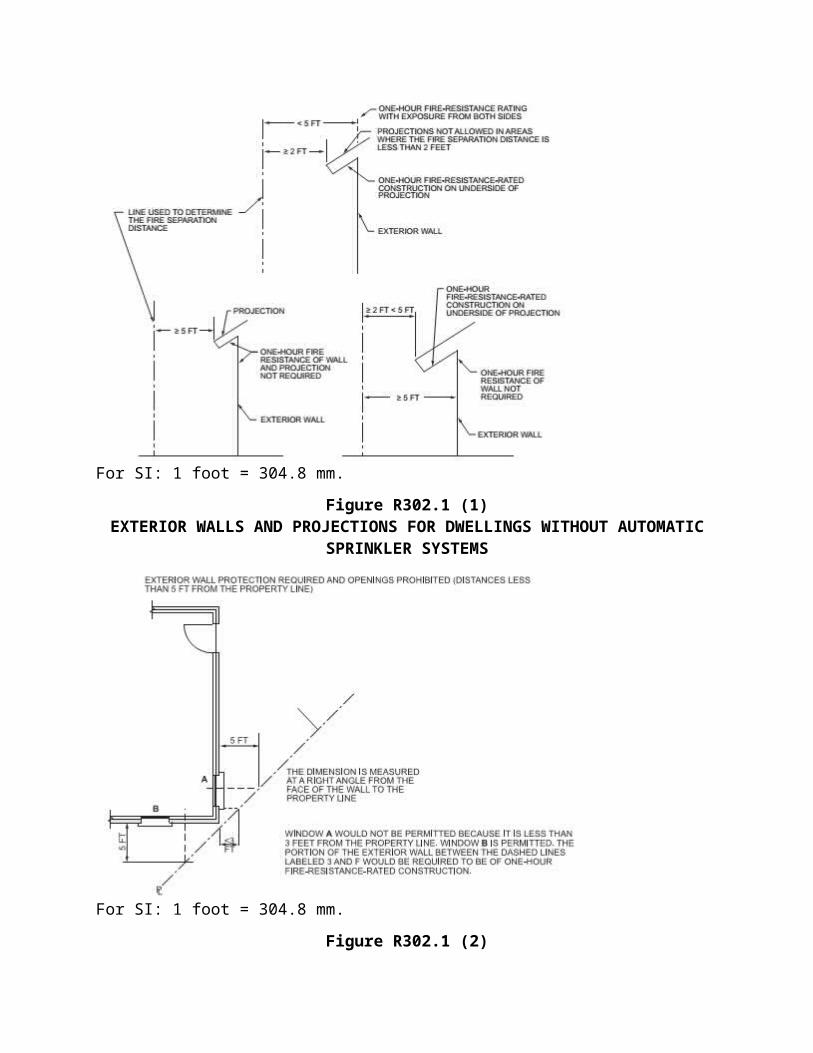
Projections cannot be closer than 2 feet (610 mm) from the lot line. Projections that have a fire separation distance of less than 5 feet (1525 mm) from the lot line in unsprinklered buildings, or less than 3 feet in sprinklered buildings, are required to be protected on the underside with 1-hour fire-resistant construction in accordance with Tables R302.1(1) and R302.1(2), respectively [see Commentary Figure R302.1(1)]. Footnotes to the tables allow the underside protection to be omitted where fireblocking is provided or gable vents openings are not present.
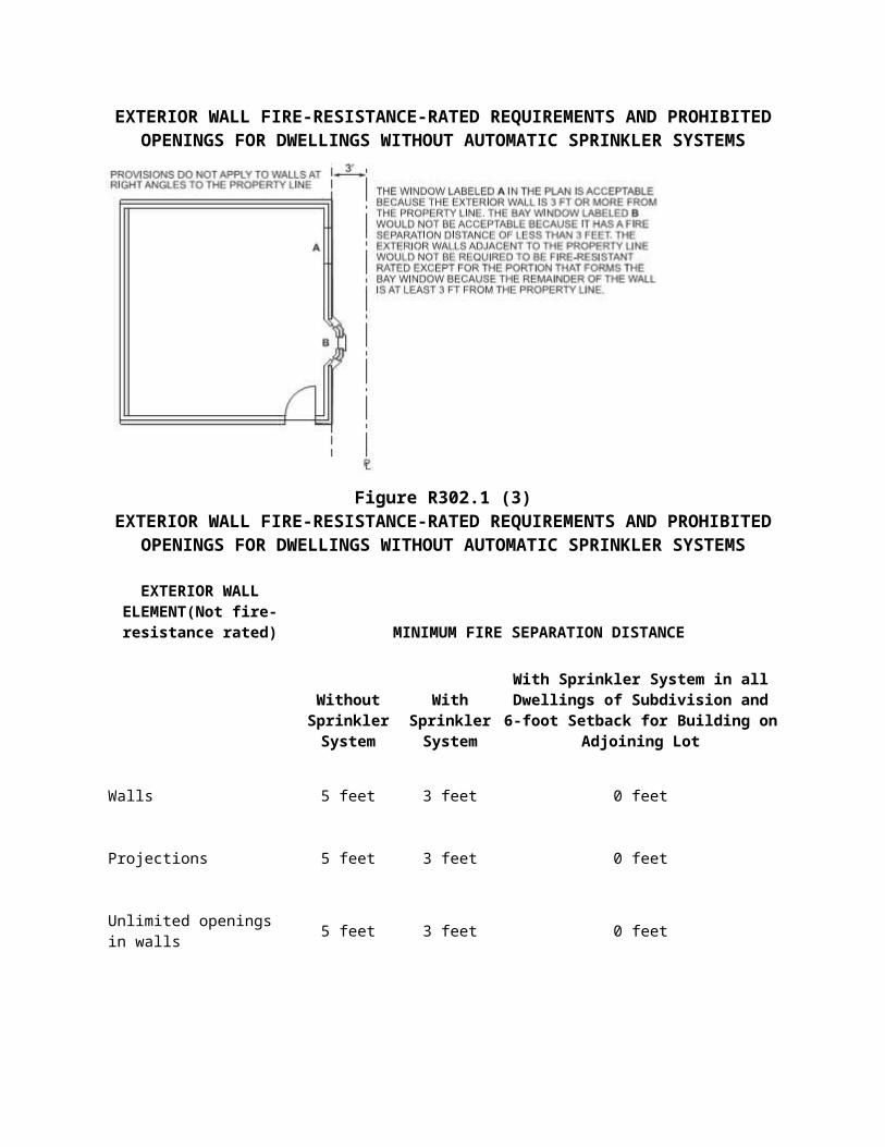
Unlike the IBC, the code does not set a distance from the property line at which openings must be protected. Openings are not permitted in exterior walls where the exterior wall has a fire separation distance of less than 3 feet (914 mm) from the lot line. Openings in a wall with a fire separation distance that is equal to or greater than 3 feet (914 mm), but less than 5 feet (1525 mm) from the lot line, cannot exceed 25 percent of the maximum wall area [see Commentary Figures R302.1(2) and R302.1(3)]. The consensus as to the minimum distance necessary to provide a sufficient buffer against the spread of fire has changed somewhat over the years. For example, the 2000 and 2003 editions of the IRC required a 3-foot (914 mm) minimum fire separation distance for unrated exterior walls. In the 2006 edition, that distance was increased to 5 feet (1525 mm) to provide a higher level of safety and to correlate with the provisions for residential occupancies regulated by the IBC. The 2009 IRC introduced requirements for automatic fire sprinkler systems in all new one- and two family dwellings and townhouses. Table R302.1 (2) permits nonrated walls that have a 3-foot (914 mm) minimum fire separation distance, a dimension previously prescribed in earlier editions of the code. The 3-foot (914 mm) dimension specified in Table R302.1(2) is the new threshold for exterior wall construction, projections, openings and penetrations for dwellings that are sprinklered in accordance with Section P2904 or NFPA 13D. For dwellings without sprinkler systems, the 5-foot (1525 mm) separation distance still applies.
The reduced clearances are intend to provide design flexibility and reduce costs associated with fire-resistant construction, while maintaining a reasonable level of safety based on past performance of dwelling fire sprinkler systems. A dwelling automatic sprinkler system installed in accordance with Section P2904 or NFPA 13D aids in the detection and control of fires in residential occupancies regulated by the IRC. The design criteria of these sprinkler systems are for life safety to buy time for occupants to escape a fire; dwelling fire sprinklers are not designed for property protection. Sprinklers in accordance with Section P2904 or NFPA 13D are not required throughout the dwelling they generally may be omitted in concealed spaces, closets, bathrooms, garages, and attics and crawl spaces without gas-fired appliances, for example. However, the automatic sprinkler system is expected to prevent total fire involvement (flashover) in the room of fire origin if the room is sprinklered. In addition to increasing the likelihood of occupants escaping or being evacuated, sprinklers often provide some measure of property protection as well.
Note a to Table R302.1(2) allows exterior walls in subdivisions where all dwellings are equipped with sprinkler systems to be placed on the lot line if the adjacent lot maintains a 6-foot (1829 mm) setback for buildings on the opposite side of the lot line. This provision allows flexibility in placing buildings on the lot for maximum effective use of the buildable area while still
maintaining a minimum 6 feet (1829 mm) of clearance between buildings. Commentary Figure R302.1 summarizes the fire separation distance requirements for exterior walls that are not fire-resistance rated.
Exception 1 permits walls, openings, projections or penetrations that are 90 degrees (1.57 rad) (perpendicular) to the line used to determine the fire separation distance to be exempt from the requirements of Tables R302.1(1) and R302.1(2). Section R302.4describes through penetrations and membrane penetrations in detail (see the definition of “Fire separation distance” in Chapter 2) [see Commentary Figures R302.1(2) and R302.1(3)].
Exception 2 allows dwellings and accessory structures, on the same lot, to be considered one building such that the requirements of Tables R302.1(1) and R302.1(2) will not apply to the exterior walls facing each other. This exception eliminates the imaginary line between two buildings on the lot when measuring the fire separation distance. Tables R302.1 (1) and R302.1 (2) will apply to the other exterior walls of the buildings.
Exception 3 applies to detached tool and storage sheds, playhouses and similar structures that are exempt from permits. Projections from these structures, however, are not permitted to extend over the property line.
Exception 4 will allow roof eave projection for detached garages to be closer than 2 feet (610 mm) from the lot line, but limits the roof eave projection to 4 inches (102 mm). This projection cannot extend over the property line.
Exception 5 allows foundation vents installed in compliance with the code in areas where openings are otherwise prohibited.
TABLE R302.1 (1).
TABLE R302.1 (1)EXTERIOR WALLS
EXTERIOR WALL ELEMENT MINIMUMFIRE-RESISTANCE RATING
MINIMUM FIRESEPARATION
DISTANCE
Walls
Fire-resistance rated
1 hour—tested in accordance with ASTM E119or UL 263 with
exposure from both sides< 5 feet
Not fire-resistance
rated0 hours ≥ 5 feet
Projections Not allowed N/A < 2 feet
Fire-resistance 1 hour on the undersidea, b ≥ 2 feet to < 5 feet
rated
Not fire-resistance
rated0 hours ≥ 5 feet
Openings in walls
Not allowed N/A < 3 feet
25% maximum of wall area 0 hours 3 feet
Unlimited 0 hours 5 feet
Penetrations All
Comply with Section R302.4 < 3 feet
None required 3 feet
For SI: 1 foot = 304.8 mm.
N/A = Not Applicable.
a.Roof eave fire-resistance rating shall be permitted to be reduced to 0 hours on the underside of the eave if fireblocking is provided from the wall top plate to the underside of the roof sheathing.b.Roof eave fire-resistance rating shall be permitted to be reduced to 0 hours on the underside of the eave provided that gable vent openings are not installed.
❖ See the commentary to Section R302.1.
TABLE R302.1 (2).
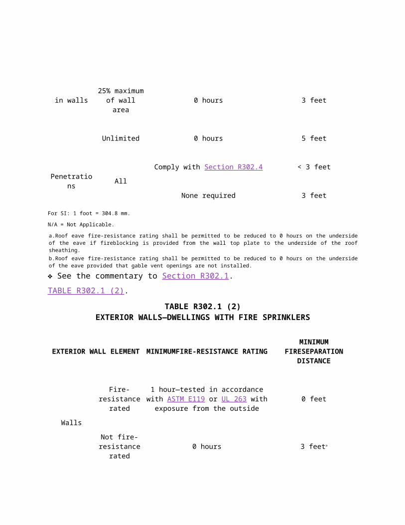
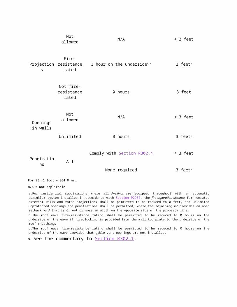
TABLE R302.1 (2)EXTERIOR WALLS—DWELLINGS WITH FIRE SPRINKLERS
EXTERIOR WALL ELEMENT MINIMUMFIRE-RESISTANCE RATINGMINIMUM
FIRESEPARATION DISTANCE
Walls Fire-resistance
rated
1 hour—tested in accordance with ASTM E119 or UL 263 with
exposure from the outside0 feet
Not fire-resistance
0 hours 3 feeta
rated
Projections
Not allowed N/A < 2 feet
Fire-resistance
rated1 hour on the undersideb, c 2 feeta
Not fire-resistance
rated0 hours 3 feet
Openings in walls
Not allowed N/A < 3 feet
Unlimited 0 hours 3 feeta
Penetrations All
Comply with Section R302.4 < 3 feet
None required 3 feeta
For SI: 1 foot = 304.8 mm.
N/A = Not Applicable
a.For residential subdivisions where all dwellings are equipped throughout with an automatic sprinkler system installed in accordance with Section P2904, the fire separation distance for nonrated exterior walls and rated projections shall be permitted to be reduced to 0 feet, and unlimited unprotected openings and penetrations shall be permitted, where the adjoining lot provides an open setback yard that is 6 feet or more in width on the opposite side of the property line.b.The roof eave fire-resistance rating shall be permitted to be reduced to 0 hours on the underside of the eave if fireblocking is provided from the wall top plate to the underside of the roof sheathing.c.The roof eave fire-resistance rating shall be permitted to be reduced to 0 hours on the underside of the eave provided that gable vent openings are not installed.
❖ See the commentary to Section R302.1.
For SI: 1 foot = 304.8 mm.
Figure R302.1 (1)EXTERIOR WALLS AND PROJECTIONS FOR DWELLINGS WITHOUT
AUTOMATIC SPRINKLER SYSTEMS
For SI: 1 foot = 304.8 mm.
Figure R302.1 (2)
EXTERIOR WALL FIRE-RESISTANCE-RATED REQUIREMENTS AND PROHIBITED OPENINGS FOR DWELLINGS WITHOUT AUTOMATIC SPRINKLER
SYSTEMS
Figure R302.1 (3)EXTERIOR WALL FIRE-RESISTANCE-RATED REQUIREMENTS AND
PROHIBITED OPENINGS FOR DWELLINGS WITHOUT AUTOMATIC SPRINKLER SYSTEMS
EXTERIOR WALL ELEMENT(Not fire-resistance rated) MINIMUM FIRE SEPARATION DISTANCE
Without Sprinkler System
With Sprinkler System
With Sprinkler System in all Dwellings of Subdivision and 6-foot Setback for
Building on Adjoining Lot
Walls 5 feet 3 feet 0 feet
Projections 5 feet 3 feet 0 feet
Unlimited openings in walls 5 feet 3 feet 0 feet
Penetrations (no restrictions) 3 feet 3 feet 0 feet
For SI: 1 foot = 304.8 mm.
Figure R302.1MINIMUM FIRE SEPARATION DISTANCE COMPARISON (NONRATED
CONSTRUCTION)
R302.2 Townhouses.Common walls separating townhouses shall be assigned a fire-resistance rating in accordance with Section R302.2, Item 1 or 2. The common wall shared by two townhouses shall be constructed without plumbing or mechanical equipment, ducts or vents in the cavity of the common wall. The wall shall be rated for fire exposure from both sides and shall extend to and be tight against exterior walls and the underside of the roof sheathing. Electrical installations shall be in accordance with Chapters 34 through 43. Penetrations of the membrane of common walls for electrical outlet boxes shall be in accordance with Section R302.4.
1. Where a fire sprinkler system in accordance with Section P2904 is provided, the common wall shall be not less than a 1-hour fire-resistance-rated wall assembly tested in accordance with ASTM E119 or UL 263.
2. Where a fire sprinkler system in accordance with Section P2904 is not provided, the common wall shall be not less than a 2-hour fire-resistance-rated wall assembly tested in accordance with ASTM E119 or UL 263.
❖ The application of this section has its basis in the exterior wall requirements found in Section R302.1 that deal with the building’s location on the lot. The definition of a townhouse in Section R202 should be reviewed, as well as the requirement for structural independence in Section R302.2.4. In general, because the “exterior wall” of the townhouse is essentially being constructed with no fire separation distance where one townhouse adjoins another, the code requires, by Section R302. 1, that the wall have not less than a 1-hour fire-resistance rating. The adjacent townhouse would have the same requirement. Therefore, the general requirement at this location (based on Sections R302.1 and R302.3) would be that each townhouse has its own fire-resistance rated “exterior wall.” This would result in the construction of two separate 1-hour walls located side by side where one townhouse adjoins another.
Because of the difficulties involved in construction and the potential for unnecessary duplication, Item 1 offers an alternative to the two separate 1-hour walls by permitting the construction of a shared or “common” wall between the townhouses. The common wall must be 1-hour fire-resistance rated in sprinklered buildings or 2-hour fire-resistance rated in unsprinkered buildings, as tested in accordance with ASTM E119 or UL 263 (see the discussion of Section R104.11 in the commentary for Section R302.1).
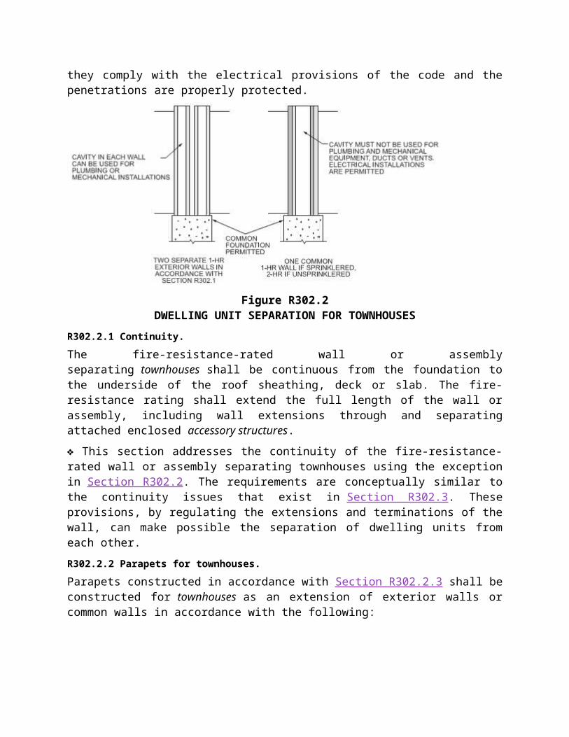
See Commentary Figure R302.2 for an illustration of the two separate 1-hour walls and the common 2-hour wall. Because the common wall has the potential to create an interconnection between the adjacent dwelling units and reduce the clear separation that would exist if two separate walls were constructed, the code places limits on services being located within the wall. This exception does not permit the inclusion of any type of plumbing, mechanical equipment, ducts or vents within the cavity of the common wall. This prohibition is applicable even if the penetrations or openings are protected by the penetration provisions of Section R302.4 or if a damper is installed in the duct or vent. The prohibition on plumbing includes all types of plumbing materials and systems, as well as water supply and drainage piping of either combustible or noncombustible materials. However, the exception permits the cavity of the wall
to be used for electrical installations if they comply with the electrical provisions of the code and the penetrations are properly protected.
Figure R302.2DWELLING UNIT SEPARATION FOR TOWNHOUSES
R302.2.1 Continuity.The fire-resistance-rated wall or assembly separating townhouses shall be continuous from the foundation to the underside of the roof sheathing, deck or slab. The fire-resistance rating shall extend the full length of the wall or assembly, including wall extensions through and separating attached enclosed accessory structures.
❖ This section addresses the continuity of the fire-resistance-rated wall or assembly separating townhouses using the exception in Section R302.2. The requirements are conceptually similar to the continuity issues that exist in Section R302.3. These provisions, by regulating the extensions and terminations of the wall, can make possible the separation of dwelling units from each other.
R302.2.2 Parapets for townhouses.Parapets constructed in accordance with Section R302.2.3 shall be constructed for townhouses as an extension of exterior walls or common walls in accordance with the following:
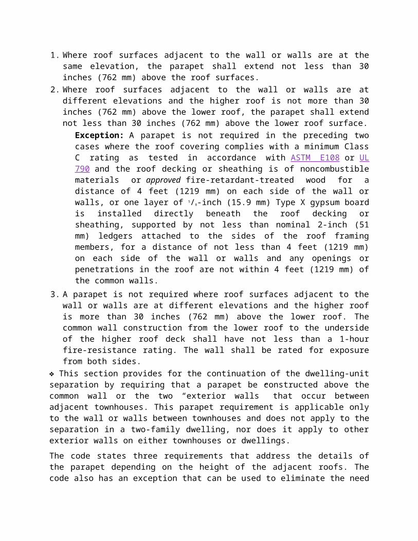
1. Where roof surfaces adjacent to the wall or walls are at the same elevation, the parapet shall extend not less than 30 inches (762 mm) above the roof surfaces.
2. Where roof surfaces adjacent to the wall or walls are at different elevations and the higher roof is not more than 30 inches (762 mm) above the lower roof, the parapet shall extend not less than 30 inches (762 mm) above the lower roof surface.
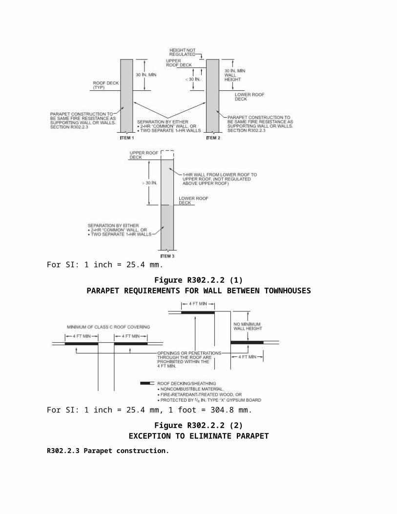
Exception: A parapet is not required in the preceding two cases where the roof covering complies with a minimum Class C rating as tested in accordance with ASTM E108 or UL 790 and the roof decking or sheathing is of noncombustible materials or approved fire-retardant-treated wood for a distance of 4 feet (1219 mm) on each side of the wall or walls, or one layer of 5/8-inch (15.9 mm) Type X gypsum board is installed directly beneath the roof decking or sheathing, supported by not less than nominal 2-inch (51 mm) ledgers attached to the sides of the roof framing members, for a distance of not
less than 4 feet (1219 mm) on each side of the wall or walls and any openings or penetrations in the roof are not within 4 feet (1219 mm) of the common walls.
3. A parapet is not required where roof surfaces adjacent to the wall or walls are at different elevations and the higher roof is more than 30 inches (762 mm) above the lower roof. The common wall construction from the lower roof to the underside of the higher roof deck shall have not less than a 1-hour fire-resistance rating. The wall shall be rated for exposure from both sides.
❖ This section provides for the continuation of the dwelling-unit separation by requiring that a parapet be constructed above the common wall or the two “exterior walls” that occur between adjacent townhouses. This parapet requirement is applicable only to the wall or walls between townhouses and does not apply to the separation in a two-family dwelling, nor does it apply to other exterior walls on either townhouses or dwellings.
The code states three requirements that address the details of the parapet depending on the height of the adjacent roofs. The code also has an exception that can be used to eliminate the need for the parapet in the two conditions that require them. In general, parapets must extend at least 30 inches (762 mm) above the roof surfaces of the adjacent townhouses. This standard requirement is found in Item 1 and is applicable where the roof surfaces of the adjacent dwelling units are at the same level, unless the exception is satisfied.
The second item requires a parapet where the roofs are at different levels, but the difference is less than 30 inches (762 mm), unless the exception is satisfied. Under this condition, the parapet height must still be 30 inches (762 mm), but it is measured only from the roof surface of the lower roof. The exception to this item indicates that a parapet is not required in this scenario if the roof is covered with a roof covering that have a minimum Class C rating as tested in accordance with ASTM E108 or UL 790 and the roof sheathing is noncombustible or fire-retardant-treated wood. Compliance with this item is not required, however, where the exception is satisfied.
The third item requires a parapet where the height difference between roofs above the common wall is more than 30 inches (762 mm) unless the common wall between the units is rated to the height of the upper roof deck. The required minimum fire-resistance rating for this portion of the wall is 1 hour.
See Commentary Figure R302.2.2 (1) for an illustration of the three requirements. See Commentary Figure R302.2.2 (2) for an illustration of the exception. Openings or penetrations through the roof are prohibited within 4 feet of the common wall or walls. It does not apply where the height difference between the roofs is more than 30 inches (762 mm) and the provisions of Item 3 have been satisfied.
For SI: 1 inch = 25.4 mm.
Figure R302.2.2 (1)PARAPET REQUIREMENTS FOR WALL BETWEEN TOWNHOUSES
For SI: 1 inch = 25.4 mm, 1 foot = 304.8 mm.
Figure R302.2.2 (2)EXCEPTION TO ELIMINATE PARAPET
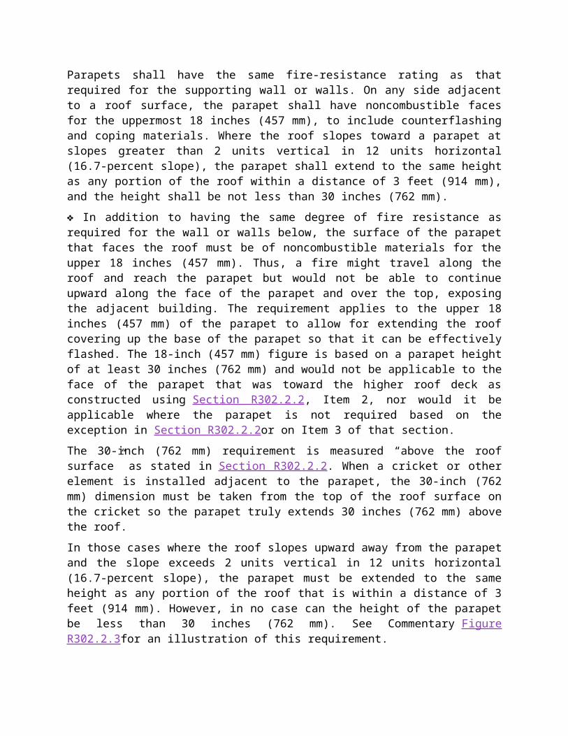
R302.2.3 Parapet construction.Parapets shall have the same fire-resistance rating as that required for the supporting wall or walls. On any side adjacent to a roof surface, the parapet shall have noncombustible faces for the
uppermost 18 inches (457 mm), to include counterflashing and coping materials. Where the roof slopes toward a parapet at slopes greater than 2 units vertical in 12 units horizontal (16.7-percent slope), the parapet shall extend to the same height as any portion of the roof within a distance of 3 feet (914 mm), and the height shall be not less than 30 inches (762 mm).
❖ In addition to having the same degree of fire resistance as required for the wall or walls below, the surface of the parapet that faces the roof must be of noncombustible materials for the upper 18 inches (457 mm). Thus, a fire might travel along the roof and reach the parapet but would not be able to continue upward along the face of the parapet and over the top, exposing the adjacent building. The requirement applies to the upper 18 inches (457 mm) of the parapet to allow for extending the roof covering up the base of the parapet so that it can be effectively flashed. The 18-inch (457 mm) figure is based on a parapet height of at least 30 inches (762 mm) and would not be applicable to the face of the parapet that was toward the higher roof deck as constructed using Section R302.2.2, Item 2, nor would it be applicable where the parapet is not required based on the exception in Section R302.2.2or on Item 3 of that section.
The 30-inch (762 mm) requirement is measured “above the roof surface” as stated in Section R302.2.2. When a cricket or other element is installed adjacent to the parapet, the 30-inch (762 mm) dimension must be taken from the top of the roof surface on the cricket so the parapet truly extends 30 inches (762 mm) above the roof.
In those cases where the roof slopes upward away from the parapet and the slope exceeds 2 units vertical in 12 units horizontal (16.7-percent slope), the parapet must be extended to the same height as any portion of the roof that is within a distance of 3 feet (914 mm). However, in no case can the height of the parapet be less than 30 inches (762 mm). See Commentary Figure R302.2.3for an illustration of this requirement.
For SI: 1 inch = 25.4 mm, 304.8 mm.
Figure R302.2.3PARAPET REQUIREMENTS
R302.2.4 Structural independence.
Each individual townhouse shall be structurally independent.
Exceptions:
1. Foundations supporting exterior walls or common walls.2. Structural roof and wall sheathing from each unit fastened to the common wall framing.3. Nonstructural wall and roof coverings.4. Flashing at termination of roof covering over common wall.5. Townhouses separated by a common wall as provided in Section R302.2, Item 1 or 2.
❖ Each townhouse must be structurally independent and capable of being removed without affecting the adjacent dwelling unit. This provision is applicable only to townhouses, not two-family dwellings. This independence is useful not only in the event of a fire in one unit, but also during any remodeling or alteration. The objective of this structural independence is that a complete burnout could occur on one side of the wall without causing the collapse of the adjacent townhouse. This condition occurs rarely. The provision also helps if there is ever a fire or other problem by creating a clear separation between the units. With separate ownership and each owner having a different insurance company, the ability to gain access or get repairs made can be difficult and time consuming. By having clearly separated units, it is much easier to determine who is responsible and to make any needed repairs.
The code lists five exceptions that waive the structural independence requirement. A quick review of the exceptions shows that they generally deal with items that will not structurally affect townhouses should a problem develop in the adjacent dwelling unit. Exception 1 is based on the norm within the industry for foundation construction. In the code, Section R402 lists only wood and concrete within the foundation materials section, although Section R404 accepts masonry foundation walls. In general, concrete and masonry are the most common types of foundations; wood foundations are viewed as unique. Given the performance of both masonry and concrete, and the fact that these foundation systems must sustain loads from both the structure and the adjacent soils, it is reasonable to assume that the foundation will not be the item that fails in most situations. Permitting a common foundation also helps solve other problems that would arise if the structural independence issue were taken as an absolute. An example where requiring separate foundations would probably create more problems or difficulty is in the dampproofing or waterproofing of below grade foundation walls.
If a wood foundation is used between adjacent units, what is the level of fire protection that may be needed? Because concrete and masonry foundations are the norm, it would be easy to forget or overlook protecting the foundation when it is constructed of wood. In these cases, it would seem appropriate to deal with the foundation as any other wall, and protect it on any exposed side. The level of fire resistance should be equal to that of the wall or walls that the foundation supports.
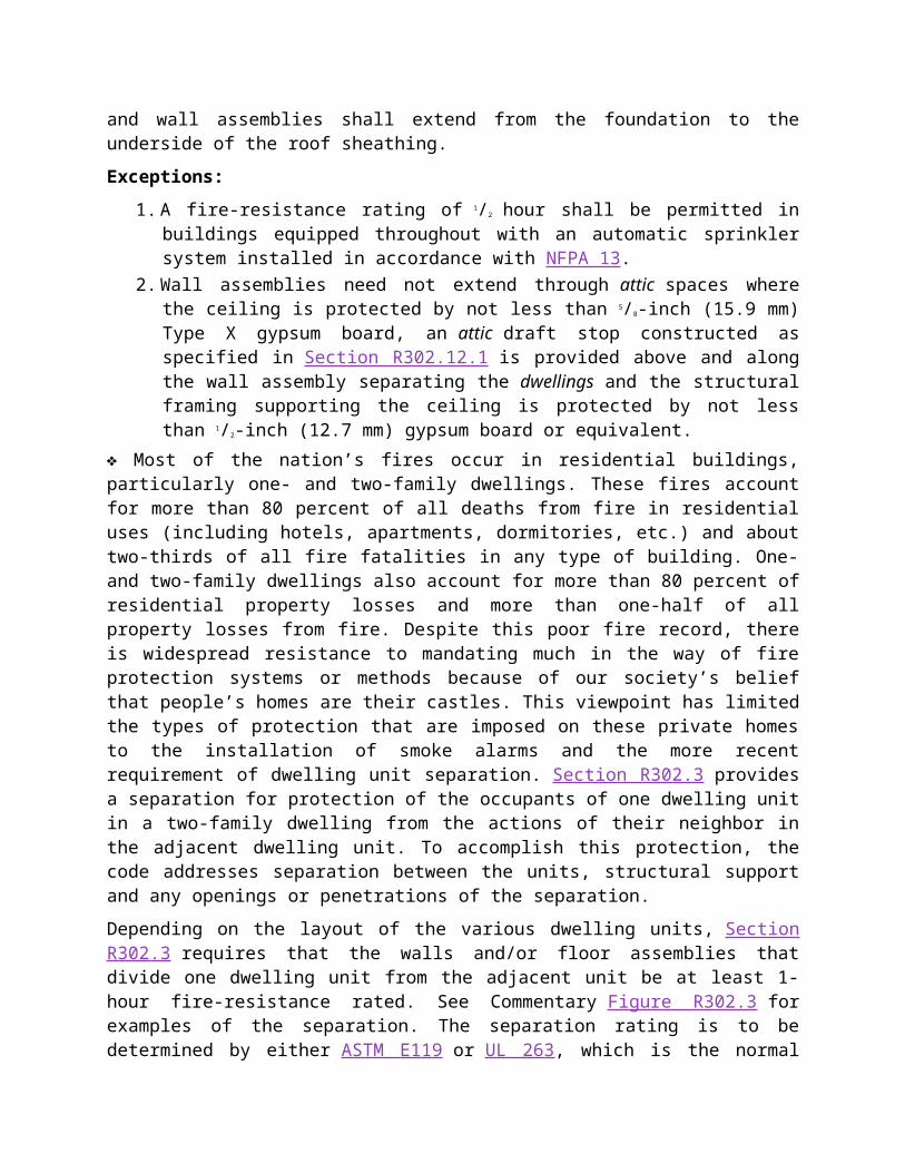
R302.3 Two-family dwellings.Dwelling units in two-family dwellings shall be separated from each other by wall and floor assemblies having not less than a 1-hour fire-resistance rating where tested in accordance with ASTM E119 or UL 263. Fire-resistance-rated floor/ceiling and wall assemblies shall extend to and be tight against the exterior wall, and wall assemblies shall extend from the foundation to the underside of the roof sheathing.
Exceptions:
1. A fire-resistance rating of 1/2 hour shall be permitted in buildings equipped throughout with an automatic sprinkler system installed in accordance with NFPA 13.
2. Wall assemblies need not extend through attic spaces where the ceiling is protected by not less than 5/8-inch (15.9 mm) Type X gypsum board, an attic draft stop constructed as specified in Section R302.12.1 is provided above and along the wall assembly separating the dwellings and the structural framing supporting the ceiling is protected by not less than 1/2-inch (12.7 mm) gypsum board or equivalent.
❖ Most of the nation’s fires occur in residential buildings, particularly one- and two-family dwellings. These fires account for more than 80 percent of all deaths from fire in residential uses (including hotels, apartments, dormitories, etc.) and about two-thirds of all fire fatalities in any type of building. One- and two-family dwellings also account for more than 80 percent of residential property losses and more than one-half of all property losses from fire. Despite this poor fire record, there is widespread resistance to mandating much in the way of fire protection systems or methods because of our society’s belief that people’s homes are their castles. This viewpoint has limited the types of protection that are imposed on these private homes to the installation of smoke alarms and the more recent requirement of dwelling unit separation. Section R302.3 provides a separation for protection of the occupants of one dwelling unit in a two-family dwelling from the actions of their neighbor in the adjacent dwelling unit. To accomplish this protection, the code addresses separation between the units, structural support and any openings or penetrations of the separation.
Depending on the layout of the various dwelling units, Section R302.3 requires that the walls and/or floor assemblies that divide one dwelling unit from the adjacent unit be at least 1-hour fire-resistance rated. See Commentary Figure R302.3 for examples of the separation. The separation rating is to be determined by either ASTM E119 or UL 263, which is the normal test used for determining fire resistance. Many tested assemblies are available for use in these locations.
The provisions of the section also address the continuity of the separation, so that one dwelling unit is completely divided from the other. The horizontal aspect of the separation, which requires that the assemblies extend to and be tight against the exterior wall, is not difficult to comply with. It is most likely the vertical aspect (continuing a wall assembly to the underside of the roof sheathing) that will require some detailed planning, careful construction and careful inspection for the units to be separated.
Exception 1 grants a reduction in the required separation for those cases in which the building is equipped with an automatic sprinkler system. In these cases, a rating of 1/2 hour is permitted versus a 1-hour fire-resistance rating. The sprinkler system must be “installed in accordance with NFPA 13,” and is to be installed “throughout” the building. The type of sprinkler system used must meet NFPA 13and may not be installed to either NFPA 13D or 13R, even though those two standards do address certain types of residential uses. The word “throughout” requires that the sprinkler system be installed in all portions of both dwelling units and any common spaces. The provisions of NFPA 13 that permit omitting sprinklers in certain areas, such as small concealed spaces, are applicable. Therefore, the provision requires a complying sprinkler system “throughout” the building (that is, in all areas of the building that must be protected according to the standard), and it does not accept any partial system, such as one installed in only one dwelling unit or only in the basement level of both units.
Exception 2 addresses separation in the area of the attic of two-family dwellings or duplexes. As long as an attic draft stop is present that meets the requirements in Section R302.12.1, the 1-hour fire separation is permitted to stop at a ceiling constructed of 5/8-inch (15.9 mm) Type X gypsum board. This may be beneficial as, in many cases, the type of truss or attic rafter and rafter tie/collar tie configuration will prohibit continuing construction of the 1-hour separation wall all the way up to the roof sheathing.
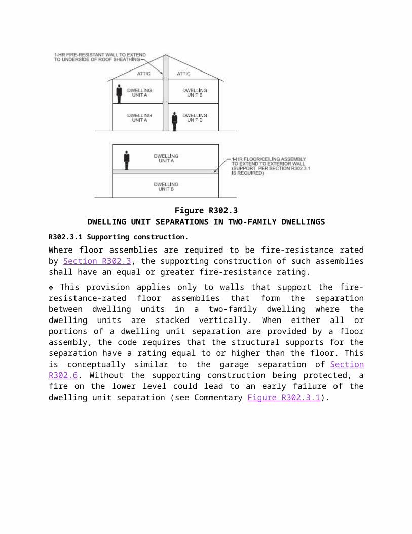
Figure R302.3DWELLING UNIT SEPARATIONS IN TWO-FAMILY DWELLINGS
R302.3.1 Supporting construction.Where floor assemblies are required to be fire-resistance rated by Section R302.3, the supporting construction of such assemblies shall have an equal or greater fire-resistance rating.
❖ This provision applies only to walls that support the fire-resistance-rated floor assemblies that form the separation between dwelling units in a two-family dwelling where the dwelling units are stacked vertically. When either all or portions of a dwelling unit separation are provided by a floor assembly, the code requires that the structural supports for the separation have a rating equal to or higher than the floor. This is conceptually similar to the garage separation of Section R302.6. Without the supporting construction being protected, a fire on the lower level could lead to an early failure of the dwelling unit separation (see Commentary Figure R302.3.1).
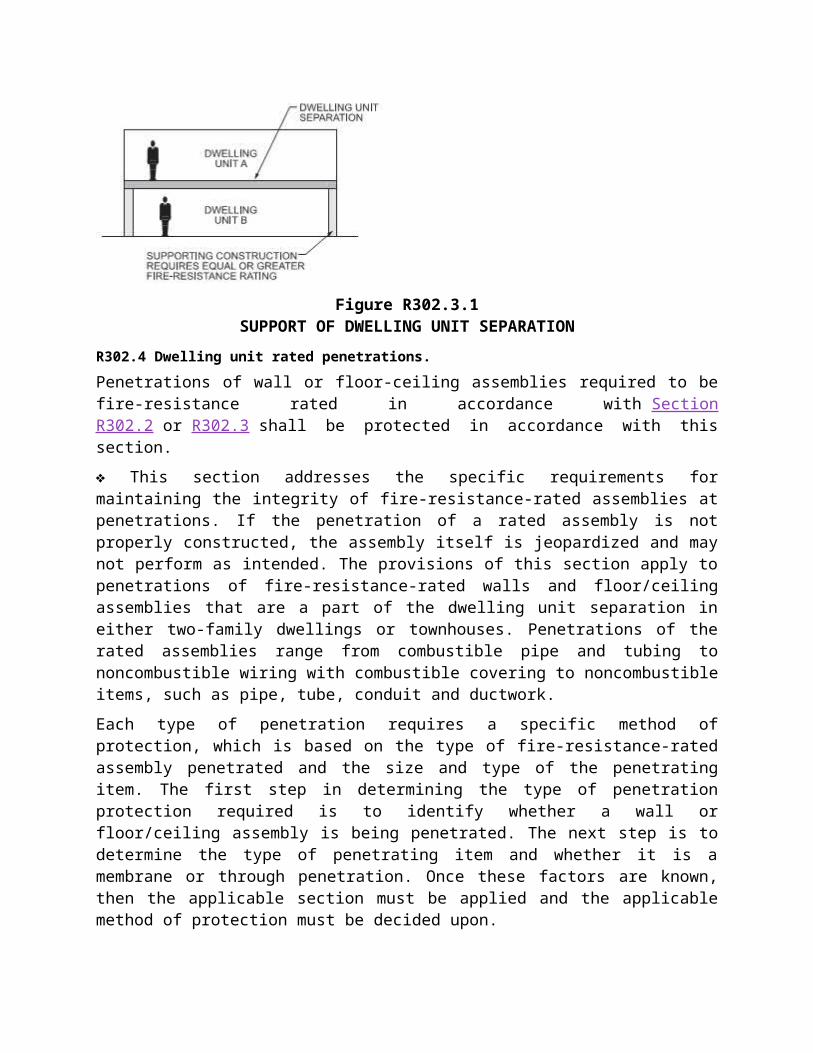
Figure R302.3.1SUPPORT OF DWELLING UNIT SEPARATION
R302.4 Dwelling unit rated penetrations.Penetrations of wall or floor-ceiling assemblies required to be fire-resistance rated in accordance with Section R302.2 or R302.3 shall be protected in accordance with this section.
❖ This section addresses the specific requirements for maintaining the integrity of fire-resistance-rated assemblies at penetrations. If the penetration of a rated assembly is not properly constructed, the assembly itself is jeopardized and may not perform as intended. The provisions of this section apply to penetrations of fire-resistance-rated walls and floor/ceiling assemblies that are a part of the dwelling unit separation in either two-family dwellings or townhouses. Penetrations of the rated assemblies range from combustible pipe and tubing to noncombustible wiring with combustible covering to noncombustible items, such as pipe, tube, conduit and ductwork.
Each type of penetration requires a specific method of protection, which is based on the type of fire-resistance-rated assembly penetrated and the size and type of the penetrating item. The first step in determining the type of penetration protection required is to identify whether a wall or floor/ceiling assembly is being penetrated. The next step is to determine the type of penetrating item and whether it is a membrane or through penetration. Once these factors are known, then the applicable section must be applied and the applicable method of protection must be decided upon.
R302.4.1 Through penetrations.Through penetrations of fire-resistance-rated wall or floor assemblies shall comply with Section R302.4.1.1 or R302.4.1.2.
Exception: Where the penetrating items are steel, ferrous or copper pipes, tubes or conduits, the annular space shall be protected as follows:
1. In concrete or masonry wall or floor assemblies, concrete, grout or mortar shall be permitted where installed to the full thickness of the wall or floor assembly or the thickness required to maintain the fire-resistance rating, provided that both of the following are complied with:1.1. The nominal diameter of the penetrating item is not more than 6 inches (152 mm).1.2. The area of the opening through the wall does not exceed 144 square inches (92 900
mm2).
2. The material used to fill the annular space shall prevent the passage of flame and hot gases sufficient to ignite cotton waste where subjected to ASTM E119 or UL 263 time temperature fire conditions under a positive pressure differential of not less than 0.01 inch of water (3 Pa) at the location of the penetration for the time period equivalent to the fire-resistance rating of the construction penetrated.
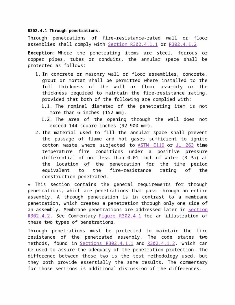
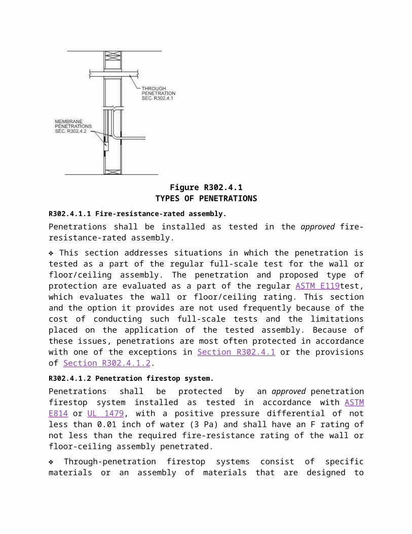
❖ This section contains the general requirements for through penetrations, which are penetrations that pass through an entire assembly. A through penetration is in contrast to a membrane penetration, which creates a penetration through only one side of an assembly. Membrane penetrations are addressed later in Section R302.4.2. See Commentary Figure R302.4.1 for an illustration of these two types of penetrations.
Through penetrations must be protected to maintain the fire resistance of the penetrated assembly. The code states two methods, found in Sections R302.4.1.1 and R302.4.1.2, which can be used to assure the adequacy of the penetration protection. The difference between these two is the test methodology used, but they both provide essentially the same results. The commentary for those sections is additional discussion of the differences.
Based on the history of these provisions and on the wealth of fire test data that exists concerning items such as conduit, water piping and other similar penetrations, the code provides two exceptions that permit protection by methods other than those generally required. The first permits the use of concrete, grout or mortar to protect certain penetrations of concrete and masonry wall or floor assemblies. The concrete, grout or mortar must be applied for the full thickness of the assembly unless evidence can be produced demonstrating that the required fire-resistance rating can be achieved with a lesser depth. Concrete, grout and mortar have traditionally been used as protection for the annular space in penetrations of concrete and masonry assemblies. Experience has shown this form of protection to be viable. However, caution must be used any time something, such as a water pipe or conduit, is placed in concrete or masonry. Sections P2603.3 and P2603.5 contain examples of protection of plumbing systems.
Exception 2 addresses the space between the penetrating item and the original assembly construction. This gap is called the annular space, and this exception provides a method to simply evaluate the performance of the material used to fill that space. It is often mistakenly believed that this exception permits a variety of untested items, but as can be seen from the provision itself, the materials need to meet a specific performance level. This exception requires that the ability of the material to prevent the passage of flame and hot gases sufficient to ignite cotton when subjected to the time-temperature criteria of the ASTM E119 test standard be prequalified. This requirement is similar to provisions found in both ASTM E119 and ASTM E814, the standards used to evaluate fire-resistant assemblies and penetration protection. Because it is very likely that the penetration in the actual fire will be exposed to a positive pressure, this section specifies that the test-fire exposure include a positive pressure of 0.01 inch (0.25 mm) of water column as a further means to verify the performance of this protection method. Thus the protection will not be blown out or moved from its place during a fire.
Figure R302.4.1TYPES OF PENETRATIONS
R302.4.1.1 Fire-resistance-rated assembly.Penetrations shall be installed as tested in the approved fire-resistance-rated assembly.
❖ This section addresses situations in which the penetration is tested as a part of the regular full-scale test for the wall or floor/ceiling assembly. The penetration and proposed type of protection are evaluated as a part of the regular ASTM E119test, which evaluates the wall or floor/ceiling rating. This section and the option it provides are not used frequently because of the cost of conducting such full-scale tests and the limitations placed on the application of the tested assembly. Because of these issues, penetrations are most often protected in accordance with one of the exceptions in Section R302.4.1 or the provisions of Section R302.4.1.2.
R302.4.1.2 Penetration firestop system.Penetrations shall be protected by an approved penetration firestop system installed as tested in accordance with ASTM E814 or UL 1479, with a positive pressure differential of not less than 0.01 inch of water (3 Pa) and shall have an F rating of not less than the required fire-resistance rating of the wall or floor-ceiling assembly penetrated.
❖ Through-penetration firestop systems consist of specific materials or an assembly of materials that are designed to restrict the passage of fire and hot gases for a prescribed period of time through openings made in fire-resistance-rated assemblies. To determine the effectiveness of a through-penetration firestop system in restricting the passage of fire, and to determine that the penetration has not jeopardized the original fire-resistant assembly, firestop systems must be subjected to fire testing using the ASTM E814 or UL 1479 test standard. This is a small-scale test method developed specifically for the evaluation of a firestop system’s ability to resist the passage of flame and hot gases, with-stand thermal stresses and restrict the transfer of heat through the penetrated assembly. There are hundreds if not thousands of tested through-penetration firestop systems available today. The actual type of system used will depend on the type and construction of the assembly being penetrated, the material makeup and size of the penetrating item, and the size of the annular space that exists between the penetrating item and the assembly being penetrated. Because there are a multitude of products available, and there is
no “one size fits all” system available, it is helpful if the methods of protection are included on the construction documents as covered by Section R106.1.1.
The actual rating of the through-penetration firestop system is generated from the results of the testing and is reported as an “F” (flame) rating and a “T” (temperature) rating. The code requires only an F rating. The F rating indicates the period of time, in hours, that the through-penetration firestop system remained in place without allowing the passage of fire during the fire exposure test, or the passage of water during the hose stream portion of the test. The required F rating must be equal to the fire-resistance rating of the wall or floor/ceiling assembly that is being penetrated. This means either a 1- or 2-hour rating, depending on the dwelling unit separation.
Two of the most common materials used in through penetration firestop systems are intumescent and endothermic materials. Intumescent materials expand approximately 8 to 10 times their original volume when exposed to temperatures exceeding 250°F (121°C). The expansion of the material fills the voids or openings within the penetration to resist the passage of flame, while the outer layer of the expanded intumescent material forms an insulating charred layer that assists in limiting the transfer of heat. The expansion properties of intumescent materials allow them to seal openings left by combustible penetrating items that burn away during a fire, but they do not retard heat as well as endothermic materials. Intumescent materials are typically used with combustible penetrating items or where a higher T rating is not required.
Endothermic materials provide protection through chemically bound water released in the form of steam when exposed to temperatures exceeding 600°F (316°C). This released water cools the penetration and retards heat transfer through the penetration. Endothermic materials tend to be superior in heat-transfer resistance and have higher T ratings, but they do not expand to fill voids left by combustible penetrating items that burn away during a fire. Therefore, endothermic materials are typically used with noncombustible penetrating items and where a higher T rating is required.
R302.4.2 Membrane penetrations.Membrane penetrations shall comply with Section R302.4.1. Where walls are required to have a fire-resistance rating, recessed fixtures shall be installed so that the required fire-resistance rating will not be reduced.
Exceptions:
1. 1.Membrane penetrations of not more than 2-hour fire-resistance-rated walls and partitions by steel electrical boxes that do not exceed 16 square inches (0.0103 m 2) in area provided that the aggregate area of the openings through the membrane does not exceed 100 square inches (0.0645 m2) in any 100 square feet (9.29 m2) of wall area. The annular space between the wall membrane and the box shall not exceed 1/8 inch (3.1 mm). Such boxes on opposite sides of the wall shall be separated by one of the following:1.1. By a horizontal distance of not less than 24 inches (610 mm) where the wall or
partition is constructed with individual noncommunicating stud cavities.1.2. By a horizontal distance of not less than the depth of the wall cavity where the wall
cavity is filled with cellulose loose-fill, rockwool or slag mineral wool insulation.1.3. By solid fireblocking in accordance with Section R302.11.1.4. By protecting both boxes with listed putty pads.1.5. By other listed materials and methods.
2. Membrane penetrations by listed electrical boxes of any materials provided that the boxes have been tested for use in fire-resistance-rated assemblies and are installed in accordance with the instructions included in the listing. The annular space between the wall membrane and the box shall not exceed 1/8 inch (3.1 mm) unless listed otherwise. Such boxes on opposite sides of the wall shall be separated by one of the following:2.1. By the horizontal distance specified in the listing of the electrical boxes.2.2. By solid fireblocking in accordance with Section R302.11.2.3. By protecting both boxes with listed putty pads.2.4. By other listed materials and methods.
3. The annular space created by the penetration of a fire sprinkler provided that it is covered by a metal escutcheon plate.
❖ This section deals with instances where only a single side of the fire-resistance-rated assembly is penetrated. This would be the situation for items such as electrical outlet boxes or plumbing fixtures located on one side of the wall only. Commentary Figure R302.4.1 shows this type of penetration. For the most part, a membrane penetration is to be protected by one of the previously described methods established for through penetrations. However, there are some penetrations that are allowed without a specific fire stopping material in the annular space around them. These are addressed by the exceptions. This section also deals with the installation of recessed luminaires in fire-resistance-rated assemblies and states that their installation may not reduce the assembly’s protection. Although these fixtures are common, they do represent a penetration of the assembly’s protection and must be installed so that the assembly is not compromised.
Exception 1 allows penetrations of steel electrical outlet boxes under certain conditions. The criteria of this section limit the size of the box to 16 square inches (0.0103 m 2) or less in area and to an aggregate area not to exceed 100 square inches (64 500 mm2) in each 100 square foot (9.3 m2) area. Commentary Figure R302.4.2 (1) shows some of the requirements of this section. The area limitations are consistent with the criteria from fire tests, which have shown that within these limitations, these penetrations will not adversely affect the fire-resistance rating of the assembly. However, the boxes are assumed to be installed as they were during the fire tests. In general, the test requirements match the limitations shown by the code regarding their size and the need to be offset. An additional requirement, one that does not appear in the code, regulates the size of the annular space created around the outlet boxes. Both the Underwriters Laboratory’s (UL) Fire-Resistance Directory and the Gypsum Association’s Fire-resistance Design Manual specify a maximum over-cut of 1/8 inch (3 mm) for the annular space around the outlet boxes. Additionally, Article 314 of the National Electrical Code (NEC) (also known as NFPA 70) includes the size limitation of the over-cut. Therefore, the exception applies only when the boxes are installed as they were during the original fire tests, including the limited annular space. Because outlet boxes on both sides of a wall create penetrations of both layers of a wall assembly’s protection, the code provides five methods to address this problem. This gives code users several options and does not limit them to the usual 24-inch (610 mm) offset.
Exception 2 permits using outlet boxes of nonmetallic materials if they have been specifically tested. Because many different types of nonmetallic boxes are available, it is important to determine that the boxes being used in the rated dwelling unit separation have been tested. Although the exception applies to nonmetallic electrical outlet boxes, the same concept would apply to steel boxes that exceed the sizes specified in Exception 1.
Exception 3 provides an alternative to the annular space protection provisions for a fire sprinkler that penetrates a single membrane. This exception is available if the annular space around the sprinkler is completely covered by an escutcheon plate of noncombustible material. The nature of the hazard posed by single membrane penetrations of the sprinkler is limited by the size of the opening, the potential number of openings present and the presence of a sprinkler system. The installation of a noncombustible escutcheon provides protection against the free passage of fire through the annular space and allows for the movement of the sprinkler piping without breaking during a seismic event [see Commentary Figure R302.4.2 (2)].
For SI: 1 inch = 25.4 mm, 1 square inch = 645 mm2, 1 square foot = 0.0929 m2.
Figure R302.4.2 (1)MEMBRANE PENETRATION BY OUTLET BOX
Figure R302.4.2 (2)EXCEPTION TO ANNULAR SPACE PROTECTION
R302.5 Dwelling-garage opening and penetration protection.Openings and penetrations through the walls or ceilings separating the dwelling from the garage shall be in accordance with Sections R302.5.1 through R302.5.3.
❖ Openings to sleeping rooms from garages are not allowed because a person might not wake up in time if there was a hazard from CO fumes or smoke from the garage. The three subsections address doors, ducts and pipes. For wall and ceiling separation requirements, see Section R302.6 and Table R302.6
R302.5.1 Opening protection.Openings from a private garage directly into a room used for sleeping purposes shall not be permitted. Other openings between the garage and residence shall be equipped with solid wood doors not less than 13/8 inches (35 mm) in thickness, solid or honeycomb-core steel doors not less than 13/8 inches (35 mm) thick, or 20-minute fire-rated doors, equipped with a self-closing device.
❖ Openings from the garage are permitted only into rooms that are not used for sleeping. These openings must be protected by the installation of a door complying with the provisions of this section. The most common situation is the door between the garage and the inside of the home. Solid wood doors 13/8-inches (35mm) thick, solid or honeycomb steel doors and 20-minute fire-rated doors are required for use in the opening between the garage and dwelling unit. A self-closing device must be installed on these doors as a safeguard to limit free flow of carbon monoxide or other products of combustion into the living area.
R302.5.2 Duct penetration.Ducts in the garage and ducts penetrating the walls or ceilings separating the dwelling from the garage shall be constructed of a minimum No. 26 gage (0.48 mm) sheet steel or other approved material and shall not have openings into the garage.
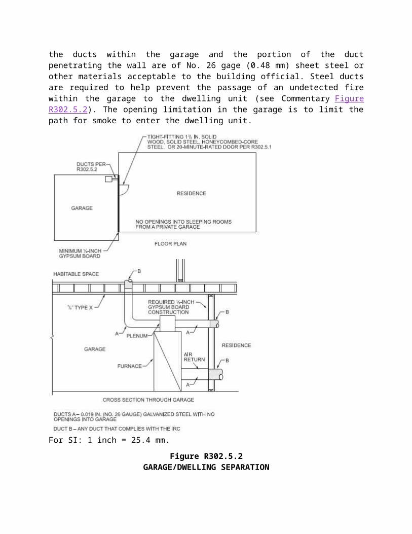
❖ Ducts are permitted to penetrate the required separation (see Section R302.6) between the garage and dwelling unit when the ducts within the garage and the portion of the duct penetrating the wall are of No. 26 gage (0.48 mm) sheet steel or other materials acceptable to the building official. Steel ducts are required to help prevent the passage of an undetected fire within the garage to the dwelling unit (see Commentary Figure R302.5.2). The opening limitation in the garage is to limit the path for smoke to enter the dwelling unit.
For SI: 1 inch = 25.4 mm.
Figure R302.5.2GARAGE/DWELLING SEPARATION
R302.5.3 Other penetrations.Penetrations through the separation required in Section R302.6 shall be protected as required by Section R302.11, Item 4.
❖ This section addresses the annular space that results from a penetration of the common wall by pipes, conduits or ductwork. It is important that the building official verify that these spaces are properly filled and do not compromise the protection offered by the common wall between the residence and garage against the free passage of smoke, fire, noxious gases and odors.
R302.6 Dwelling-garage fire separation.
The garage shall be separated as required by Table R302.6. Openings in garage walls shall comply with Section R302.5. Attachment of gypsum board shall comply with Table R702.3.5. The wall separation provisions of Table R302.6 shall not apply to garage walls that are perpendicular to the adjacent dwelling unit wall.
❖ Numerous potential hazards exist within garages because occupants of dwelling units tend to store a variety of hazardous materials there. Along with this and the potential for CO build-up within the garage, the code requires that the garage be separated from the dwelling unit and attic as indicated in Table R302.6. Garage walls and ceilings that do not form a separation from the dwelling unit are not required to be rated unless they are an extension of a rated assembly.
TABLE R302.6.
TABLE R302.6DWELLING-GARAGE SEPARATION
SEPARATION MATERIAL
From the residence and attics Not less than 1/2-inch gypsum board or equivalent applied to the garage side
From habitable rooms above the garage Not less than 5/8-inch Type X gypsum board or equivalent
Structure(s) supporting floor/ceiling assemblies used for separation required by this section
Not less than 1/2-inch gypsum board or equivalent
Garages located less than 3 feet from a dwelling unit on the same lot
Not less than 1/2-inch gypsum board or equivalent applied to the interior side of exterior walls that are within this area
For SI: 1 inch = 25.4 mm, 1 foot = 304.8 mm.
❖ This table specifies when and how the garage must be separated from the dwelling unit and any attic space. Walls between the residence and the attached garage, or ceilings between the garage and an attic space, must have at least 1/2-inch (12.7 mm) gypsum board on the garage side. If a habitable room is above the garage, the ceiling must be at least 5/8-inch (15.9 mm) Type X gypsum board on the garage side. Additionally, the exterior walls of the garage are required to have 1/2-inch (12.7 mm) gypsum board on the interior face where they support floors separating all or part of a dwelling unit above the garage.
Detached garages located less than 3 feet (305 mm) from an adjacent dwelling unit must be protected with at least 1/2-inch (12.7 mm) gypsum board applied to the interior side of the garage. The close proximity to adjacent dwellings requires the additional protection. This1/2-inch (12.7 mm) gypsum board is required even when the exterior walls are exempted by Section R302.1.
The term “or equivalent” under each option allows for alternative means consistent with Section R104.11.
There are two primary reasons for the enhanced fire endurance of a garage ceiling located beneath a habitable room. First, a fire occurring in a garage may well go undetected for an extended period prior to activation of a detector or other visual alerting.
Second, the inherent fire load and hazardous household activities associated with a garage necessitate this additional level of protection if fire suppression forces are to have a reasonable opportunity to contain a garage fire to the area of origin.
The single layer of 5/8-inch (15.9 mm) Type X gypsum board at the garage ceiling increases the fire endurance of the assembly considerably, from 15 minutes for a 1/2-inch (12.7 mm) layer, to at least 40 minutes, or a 167-percent increase in endurance. When added to the rating for floor joists and certain subflooring combinations, the final endurance is close to 1 hour.
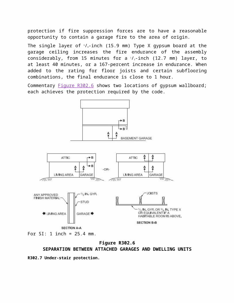
Commentary Figure R302.6 shows two locations of gypsum wallboard; each achieves the protection required by the code.
For SI: 1 inch = 25.4 mm.
Figure R302.6SEPARATION BETWEEN ATTACHED GARAGES AND DWELLING UNITS
R302.7 Under-stair protection.
Enclosed accessible space under stairs shall have walls, under-stair surface and any soffits protected on the enclosed side with 1/2-inch (12.7 mm) gypsum board.
❖ Often times the space under a stairway is used for storage because this space is often of little use for other purposes. The code permits the use of an open space beneath a stair without the need for any additional protection. Additionally, if the space is walled off and there is no access to the area, the code is also not concerned. If, however, the area beneath the stairway is enclosed and any type of access is provided into the space, the walls, soffits and ceilings of the enclosed space must be protected on the enclosed side with at least 1/2-inch (12.7 mm) gypsum board.
R302.8 Foam plastics.For requirements for foam plastics, see Section R316.
❖ This section provides a cross reference to the foam plastic fire-resistant requirements for when this product is used within a home. Foam plastics are most commonly used in applications where their thermal qualities can be a cost savings for the home owner over time.
R302.9 Flame spread index and smoke-developed index for wall and ceiling finishes.Flame spread and smoke developed indexes for wall and ceiling finishes shall be in accordance with Sections R302.9.1through R302.9.4.
❖ Wall and ceiling finishes have requirements for flame spread and smoke-developed indexes, and testing, which are addressed in the following subsections.
R302.9.1 Flame spread index.Wall and ceiling finishes shall have a flame spread index of not greater than 200.
Exception: Flame spread index requirements for finishes shall not apply to trim defined as picture molds, chair rails, baseboards and handrails; to doors and windows or their frames; or to materials that are less than 1/28 inch (0.91 mm) in thickness cemented to the surface of walls or ceilings if these materials exhibit flame spread index values not greater than those of paper of this thickness cemented to a noncombustible backing.
❖ The control of interior finishes is an important aspect of fire protection. Section R315.9 contains the requirements for controlling fire growth within buildings by restricting interior finish materials. The dangers of unregulated interior finish include both the rapid spread of fire and the contribution of additional fuel to the fire. The rapid spread of fire presents a threat to the occupants of a building by limiting or denying their use of exit ways within and outside the building. This can be caused by the rapid spread of the fire itself or by the production of large quantities of dense, black smoke, which obscures the exit path or makes movement difficult. Unregulated finish materials also have the potential for adding fuel to the fire, thus increasing its intensity and shortening the time available for the occupants to exit safely. However, based on the test standard that is used, the code does not regulate the fuel contribution of interior finish materials.
The code regulates interior finish materials on both walls and ceilings. These provisions do not address the floor or any coverings applied to the floor. The level of performance the code establishes for finish materials is a flame spread index of 200 or less. The flame spread index for a material is based on reviewing its performance under the test standard specified in Section R302.9.3. The limitation of 200 for the flame spread index matches a “Class C” material in
the IBC. Therefore, any material that has a flame spread index of less than 200 may be used as a finish material on both walls and ceilings. When foam plastics are used for interior wall and ceiling finishes, they must comply with Section R316.5.10.
The exception will permit the installation of materials that will not significantly contribute to a fire. This includes various types of trim, such as chair rails, door and window frames, and baseboards, which because of their quantities and locations, do not cause great concern. The actual size and quantity of such trim is not specified in the code because it has not been a concern. However, if some type of foam plastic is being used instead of other types of combustible trim, Section R316.5.9 does limit those situations. The exception also does not regulate thin materials, such as wallpaper, which are less than 1/28-inch (0.907 mm) thick when they are properly installed. These thin materials, when cemented to the surface of the wall or ceiling, behave essentially as the backing to which they are applied and, as a result, are not regulated.
R302.9.2 Smoke-developed index.Wall and ceiling finishes shall have a smoke-developed index of not greater than 450.
❖ The development of smoke affects the occupants’ safety. This section places a limitation of 450 on the density of smoke that is allowed from the wall and ceiling finishes. A product’s smoke-developed index is established for the finish materials when they are tested under the standard specified in Section R302.9.3. The test measures only the obscurity caused by the smoke and does not consider the toxic content within the smoke.
R302.9.3 Testing.Tests shall be made in accordance with ASTM E84 or UL 723.
❖ This section establishes that the standard test for flame spread and smoke-development characteristics is either ASTM E84 or UL 723, commonly known as the Steiner Tunnel Test. ASTM E84 and UL 723 determine the relative burning behavior of materials on exposed surfaces, such as ceilings and walls, by visually observing the flame spread along the test specimen. Flame spread and smoke density are reported. The test method renders measurements of surface flame spread and smoke density in comparison with test results obtained by using select red oak and asbestos cement board as control materials. Red oak is used for the furnace calibration because it is a fairly uniform grade of lumber that is readily available nationally, is uniform in thickness and moisture content, and generally gives consistent and reproducible results. Asbestos-cement board has a flame spread index of zero, while the red oak is assigned a flame spread index of100. All other materials are then given an index based on a comparison with these two materials. Therefore, the flame spread index of 200 that is permitted by Section R302.9.1 essentially means that the maximum flame spread index for any finish material is twice that of the sample specimen of red oak.
R302.9.4 Alternative test method.As an alternative to having a flame spread index of not greater than 200 and a smoke-developed index of not greater than 450 where tested in accordance with ASTM E84 or UL 723, wall and ceiling finishes shall be permitted to be tested in accordance with NFPA 286. Materials tested in accordance with NFPA 286 shall meet the following criteria:
The interior finish shall comply with the following:
1. During the 40 kW exposure, flames shall not spread to the ceiling.2. The flame shall not spread to the outer extremity of the sample on any wall or ceiling.3. Flashover, as defined in NFPA 286, shall not occur.4. The peak heat release rate throughout the test shall not exceed 800 kW.5. The total smoke released throughout the test shall not exceed 1,000 m2.❖ This section allows the use of NFPA 286 instead of ASTM E84 or UL 723 for testing of wall and ceiling finishes other than textiles. NFPA 286 is known as a “room corner” fire test. In this test, a fire source consisting of a wood crib is placed in the corner of a compartment. The materials tested are then placed on the walls of the compartment (see Commentary Figure R302.9.4). This generally provides a more realistic understanding of the hazards involved with the materials.
Two levels of exposures are used during an NFPA 286 fire test to better represent a growing fire. The first is a 40-kW fire size for 5 minutes and then a 160-kWexposure for 10 minutes. The 40-kW exposure represents the beginning of a fire where the initial spread is critical. Therefore, the stated criterion is that the fire cannot spread to the ceiling. The 160-kW exposure is obviously a more intense fire and the criterion relates to preventing flashover (as defined by NFPA 286) and the extent of flame spread throughout the entire test assembly. There is also a peak heat release limit of 800kw and a total smoke production limit of 1,000 square feet (92.9 m 2) for both levels of exposure.
It should be noted that the flashover criteria for NFPA 286 are as follows:
Heat release exceeds 1 MW, Heat flux at the floor exceeds 20 kW/m2, Average upper layer temperature exceeds 600°C (1112°F), Flames exit the doorway, and Auto ignition of paper target on the floor occurs.
For SI: 1 inch = 25.4 mm, 1 foot = 304.8 mm.
Figure R302.9.4
INTERIOR FIRE TEST ROOM DIMENSIONS
R302.10 Flame spread index and smoke-developed index for insulation.Flame spread and smoke-developed index for insulation shall be in accordance with Sections R302.10.1 through R302.10.5.
❖ Section R302.10 addresses insulating materials installed in building spaces. Insulating materials can affect fire development and fire spread and, therefore, are regulated. Insulation has requirements for flame spread, smoke development, critical radiant flux and testing, which are addressed in the following subsections. There are unique testing requirements for loose-fill insulations.
R302.10.1 Insulation.Insulation materials, including facings, such as vapor retarders and vapor-permeable membranes installed within floor-ceiling assemblies, roof-ceiling assemblies, wall assemblies, crawl spaces and attics shall have a flame spread index not to exceed 25 with an accompanying smoke-developed index not to exceed 450 where tested in accordance with ASTM E84 or UL 723.
Exceptions:
1. Where such materials are installed in concealed spaces, the flame spread index and smoke-developed index limitations do not apply to the facings, provided that the facing is installed in substantial contact with the unexposed surface of the ceiling, floor or wall finish.
2. Cellulose fiber loose-fill insulation, that is not spray applied, complying with the requirements of Section R302.10.3, shall not be required to meet the smoke-developed index of not more than 450 and shall be required to meet a smoke-developed index of not more than 450 where tested in accordance with CAN/ULC S102.2.
3. Foam plastic insulation shall comply with Section R316.❖ Section R302.10.1 addresses the various insulating materials that may be installed in building spaces, including insulating batts, blankets, fills (including vapor barriers and vapor-permeable membranes) and other coverings. Exposed insulating materials represent the same fire exposure hazard as any other exposed material, such as an interior finish. The provisions of Sections R302.10.2, R302.10.3 and R302.10.4, as well as the foam plastic provisions of Section R316, should also be reviewed based on the actual type of insulation and how it is installed. As a general requirement, insulation, including facings used as vapor retarders or as breather papers, must have a flame spread index not in excess of 25 and a smoke-developed index not in excess of 450. These values limit the contribution of the insulation to a fire. The flame spread requirement of 25 for the insulation will be more limiting than the 200, which is accepted for interior finishes by Section R302.9. The test method used to establish these limits is either ASTM E84 or UL 723. See the commentary to Section R302.9.3 for additional information.
Exceptions 1 and 2 address situations where, because of the way the material is installed or because of other imposed regulations, the material does not make any significant contribution to a fire.
The first exception eliminates the flame spread and smoke-developed indexes for the facing portion of the insulation if it is installed “in substantial contact” with the unexposed surface of
the ceiling, floor or wall finish. For example, when paper-backed insulation is placed directly on top of a ceiling, the paper facing is not required to meet the smoke and flame spread limits. If the same material is applied to the underside of a roof deck and the paper facing is exposed to the attic space, the paper facing must then meet the general criteria. The potential for flame spread is greatly diminished when the facings are installed in direct contact with the finish material because of the lack of airspace to support a fire if the facing were to be exposed to a source of ignition. See Commentary Figure R302.10.1 for an example of the various facing provisions.
The second exception addresses the fact that cellulosic fiber loose-fill insulation is federally regulated by the Consumer Product Safety Commission (CPSC). Parts 1209 and 1404 of CPSC 16 CFR contain various requirements that regulate the product to avoid excessive flammability or significant fire hazards. The smoke-developed index for cellulosic fiber loose-fill insulation that is spray applied must be 450 or less, as tested in accordance with CAN/ULC S102.2.
Exception 3 points the user to Section R316 for foam plastic insulation. Foam plastic materials pose some different problems that are addressed in Section R316.
Figure R302.10.1INSULATION FACING
R302.10.2 Loose-fill insulation.Loose-fill insulation materials that cannot be mounted in the ASTM E84 or UL 723 apparatus without a screen or artificial supports shall comply with the flame spread and smoke-developed limits of Section R302.10.1 where tested in accordance with CAN/ULC S102.2.
Exception: Cellulosic fiber loose-fill insulation shall not be required to be tested in accordance with CAN/ULC S102.2, provided such insulation complies with the requirements of Sections R302.10.1 and R302.10.3.
❖ The main provision establishes that CAN/ULC S102.2 is used as the test standard to determine the flame spread and smoke-developed indexes for cellulosic fiber loose-fill insulation materials that cannot be tested using the normal ASTM E84 or UL 723test method. The exception makes a distinction between cellulosic fiber insulation that is spray applied using a
water-mist spray applicator and cellulose loose-fill insulation that is poured or blown into place. Spray-applied cellulosic fiber insulation can be exposed on vertical and horizontal ceiling-type surfaces, so it is tested like any other insulating material. Cellulosic fiber loose-fill insulation that is poured (see commentary to Section R302.10.1, Exception 2) is exempt from the test procedure described in this section.
R302.10.3 Cellulosic fiber loose-fill insulation.Cellulosic fiber loose-fill insulation shall comply with CPSC 16 CFR, Parts 1209 and 1404. Each package of such insulating material shall be clearly labeled in accordance with CPSC 16 CFR, Parts 1209 and 1404.
❖ Because cellulosic fiber loose-fill insulation is federally regulated, this section provides the reference to the various federal regulations that are to be used. Because the federal regulations have precedence, the code cannot impose other requirements on this product. Therefore, this section and the reference to it from Section R302.10.1, Exception 2, establish the requirements for this product and provide the exemption from the normal ASTM E84 or UL 723 test standards.
R302.10.4 Exposed attic insulation.Exposed insulation materials installed on attic floors shall have a critical radiant flux not less than 0.12 watt per square centimeter.
❖ This section provides the performance requirements for the test exposure that insulation must meet when it is exposed on the floor of an attic. It is tied to the testing provisions found in Section R302.10.5, which specifies that the ASTM E970 test is to be used for determining the critical radiant flux. See the commentary to Section R302.10.5 regarding the application of this requirement to cellulosic fiber loose-fill insulation.
R302.10.5 Testing.Tests for critical radiant flux shall be made in accordance with ASTM E970.
❖ ASTM E970 is a test method developed by the insulation industry to evaluate the fire hazard of exposed attic insulation and is referenced in the material standards for insulation. Cellulosic fiber loose-fill insulation must comply with CPSC 16 CFR, Part 1209(see Section R302.10.3), which requires testing by this standard. Spray-applied cellulose insulation that is not subject to the CPSC standard (see Section R302.10.1 and Exception 2 in that section) is also subject to the ASTM E970 testing by Section R302.10.4.
R302.11 Fireblocking.In combustible construction, fire-blocking shall be provided to cut off both vertical and horizontal concealed draft openings and to form an effective fire barrier between stories, and between a top story and the roof space.
Fireblocking shall be provided in wood-framed construction in the following locations:
1. In concealed spaces of stud walls and partitions, including furred spaces and parallel rows of studs or staggered studs, as follows:1.1. Vertically at the ceiling and floor levels.1.2. Horizontally at intervals not exceeding 10 feet (3048 mm).
2. At interconnections between concealed vertical and horizontal spaces such as occur at soffits, drop ceilings and cove ceilings.
3. In concealed spaces between stair stringers at the top and bottom of the run. Enclosed spaces under stairs shall comply with Section R302.7.
4. At openings around vents, pipes, ducts, cables and wires at ceiling and floor level, with an approved material to resist the free passage of flame and products of combustion. The material filling this annular space shall not be required to meet the ASTM E136 requirements.
5. For the fireblocking of chimneys and fireplaces, see Section R1003.19.6. Fireblocking of cornices of a two-family dwelling is required at the line of dwelling
unit separation.❖ To restrict the movement of flame and gasses to other areas of a building through concealed passages in building components, such as floors, walls and stairs, fire blocking of these concealed combustible spaces is required to form a barrier between stories, and between a top story and the roof space. For example, the following locations must be firestopped in wood frame construction:
Concealed spaces of stud walls and partitions, including spaces at the ceiling and floor levels [see Commentary Figures R302.11 (1) and R302.11 (2)].
Interconnections between concealed vertical and horizontal spaces such as soffits [see Commentary Figure R302.11(3)], dropped ceilings [see Commentary Figure R302.11(4)] and cove ceilings [see Commentary Figure R302.11(5)]. Interconnections shown in Commentary Figure R302.11 (6) for a bathtub installation must also be fire stopped.
Concealed spaces between stair stringers at the top and bottom of the run [see Commentary Figure R302.11 (7)].
Openings around vent pipes, ducts, chimneys and fireplaces at ceiling and floor levels [see Commentary Figures R302.11 (8) and R302.11 (9)]. By not requiring compliance with ASTM E136, Item 4 indicates that the fireblocking material can be of combustible materials. Commentary Figure R302.11 (9) illustrates noncombustible fireblocking at masonry chimneys and fireplaces as required in accordance with Section R1003.19. The fireblocking at the duct work would be similar, but is not required to be noncombustible.
Figure R302.11 (1)FIRESTOPPING—BALLON FRAMING
Figure R302.11 (2)FIRESTOPPING—PLATFORM FRAMING
Figure R302.11 (3)FIRESTOPPING—FURRED SOFFIT
Figure R302.11 (4)FIRESTOPPING—DROPPED CEILING
Figure R302.11 (5)FIRESTOPPING—COVE CEILING
Figure R302.11 (6)FIRESTOPPING—AT TUB
Figure R302.11 (7)FIRESTOPPING—AT STAIRWAYS
Figure R302.11 (8)FIRESTOPPING—AROUND PIPING
Figure R302.11 (9)FIRESTOPPING—AROUND MASONRY CHIMNEYS AND FIREPLACES
R302.11.1 Fireblocking materials.Except as provided in Section R302.11, Item 4, fireblocking shall consist of the following materials.
1. Two-inch (51 mm) nominal lumber.2. Two thicknesses of 1-inch (25.4 mm) nominal lumber with broken lap joints.3. One thickness of 23/32-inch (18.3 mm) wood structural panels with joints backed by 23/32-inch
(18.3 mm) wood structural panels.4. One thickness of 3/4-inch (19.1 mm) particleboard with joints backed by 3/4-inch (19.1
mm) particleboard.5. One-half-inch (12.7 mm) gypsum board.6. One-quarter-inch (6.4 mm) cement-based millboard.7. Batts or blankets of mineral wool or glass fiber or other approved materials installed in such
a manner as to be securely retained in place.8. Cellulose insulation installed as tested in accordance with ASTM E119 or UL 263, for the
specific application.❖ This section specifies the material required for fireblocking. Fireblocking around chimneys and fireplaces must be noncombustible according to Section R1003.19 as specified in Item 5 of Section R302.11.The fireblocking at openings around vents, pipes, ducts and wires at the ceiling and floor level is required only to be adequate to resist the free passage of flames and smoke according to Item 4 of Section R302.11; however, this fireblocking can be constructed from combustible materials. So that it is not accidentally displaced, all fireblocking material must be securely fastened in place.
R302.11.1.1 Batts or blankets of mineral or glass fiber.Batts or blankets of mineral or glass fiber or other approved non rigid materials shall be permitted for compliance with the 10-foot (3048 mm) horizontal fireblocking in walls constructed using parallel rows of studs or staggered studs.
❖ Batts or blankets may serve as horizontal fireblocking in walls where they are installed in accordance with Sections R302.11.1.2 through R302.11.1.3.
R302.11.1.2 Unfaced fiberglass.Unfaced fiberglass batt insulation used as fireblocking shall fill the entire cross section of the wall cavity to a height of not less than 16 inches (406 mm) measured vertically. Where piping, conduit or similar obstructions are encountered, the insulation shall be packed tightly around the obstruction.
❖ When batts or blankets are used for fireblocking they must fill the wall cavity from stud to stud and be at least 16 inches (406 mm) as measured from the bottom to the top of the fill.
R302.11.1.3 Loose-fill insulation material.Loose-fill insulation material shall not be used as a fireblock unless specifically tested in the form and manner intended for use to demonstrate its ability to remain in place and to retard the spread of fire and hot gases.
❖ Not every type of batt or blanket insulation is acceptable as a fireblocking material. Testing must show that the type utilized will provide the intended protection.
R302.11.2 Fireblocking integrity.The integrity of fire-blocks shall be maintained.
❖ Piping, ducts or other similar items that pass through fire stops must be installed so that the integrity of the firestop is maintained. This may be accomplished by packing an oversized hole with an acceptable fireblocking material.
R302.12 Draftstopping.In combustible construction where there is usable space both above and below the concealed space of a floor-ceiling assembly, draftstops shall be installed so that the area of the concealed space does not exceed 1,000 square feet (92.9 m2). Draftstopping shall divide the concealed space into approximately equal areas. Where the assembly is enclosed by a floor membrane above and a ceiling membrane below, draftstopping shall be provided in floor-ceiling assemblies under the following circumstances:
1. Ceiling is suspended under the floor framing.2. Floor framing is constructed of truss-type open-web or perforated members.❖ Draftstopping is required to limit the spread of fire through combustible spaces in floor/ceiling assemblies when such spaces create a connected area beyond the normal joist cavity. For example, draftstopping is required when the ceiling is suspended under the floor framing, as illustrated in Commentary Figure R302.12(1), or when the floor framing is constructed of truss-type or open-web perforated members, as illustrated in Commentary Figure R302.12(2). When such space exceeds 1,000 square feet (92.9 m2) in area, the code requires the space between the ceiling membrane and the floor to be divided into two approximately equal areas with no area larger than 1,000 square feet (92.9 m2). A floor/ceiling assembly having a space exceeding 2,000 square feet (185.8 m2), but not exceeding 3,000 square feet (278.7 m2), would have to be divided into a minimum of three approximately equal areas.
Figure 302.12(1)DRAFTSTOPPING OF CEILING SUSPENDED UNDER FLOOR FRAMING
Figure 302.12(2)DRAFTSTOPPING OF TRUSS-TYPE FLOOR FRAMING
R302.12.1 Materials.Draftstopping materials shall be not less than 1/2-inch (12.7 mm) gypsum board, 3/8-inch (9.5 mm) wood structural panels or other approved materials adequately supported. Draftstopping shall be installed parallel to the floor framing members unless otherwise approved by the building official. The integrity of the draftstops shall be maintained.
❖ Materials used to meet draftstopping requirements are typically 1/2-inch (12.7 mm) gypsum board or 3/8-inch (9.5 mm) plywood adequately attached to the supporting members. Other materials may be used for draftstopping, if those materials produce an equivalent barrier.
The code places an additional restriction on the specific location of the draftstopping, mandating that the draft stopping be placed parallel to the main floor framing members. Commentary Figures R302.12 (1) and R302.12 (2) illustrate two examples of draftstopping orientation placed as required.
When a penetration through the draftstopping is necessary, the integrity of the draftstop must be maintained in a manner similar to firestopping penetrations.
R302.13 Fire protection of floors.Floor assemblies that are not required elsewhere in this code to be fire-resistance rated, shall be provided with a 1/2-inch (12.7 mm) gypsum wallboard membrane, 5/8-inch (16 mm) wood structural panel membrane, or equivalent on the underside of the floor framing member. Penetrations or openings for ducts, vents, electrical outlets, lighting, devices, luminaires, wires, speakers, drainage, piping and similar openings or penetrations shall be permitted.
Exceptions:
1. Floor assemblies located directly over a space protected by an automatic sprinkler system in accordance with Section P2904, NFPA 13D, or other approved equivalent sprinkler system.
2. Floor assemblies located directly over a crawl space not intended for storage or fuel-fired appliances.
3. Portions of floor assemblies shall be permitted to be unprotected where complying with the following:3.1. The aggregate area of the unprotected portions does not exceed 80 square feet (7.4
m2) per story3.2. Fireblocking in accordance with Section R302.11.1 is installed along the perimeter of
the unprotected portion to separate the unprotected portion from the remainder of the floor assembly.
4. Wood floor assemblies using dimension lumber or structural composite lumber equal to or greater than 2-inch by 10-inch (50.8 mm by 254 mm) nominal dimension, or other approved floor assemblies demonstrating equivalent fire performance.
❖ During a fire unprotected floor assemblies of light-weight construction have a short time gap between untenable conditions and the structural collapse of the floor assembly. Section R302.1.3 requires protection to floors of light-weight construction that will provide the occupants additional time for self-evacuation and safety for fire fighters performing search and rescue. This section requires all floor assemblies, not fire rated, to be protected on the underside with 1/2-inch gypsum board, 5/8-inch wood structural panels or equivalent. This will apply mainly to floor assemblies located over nonsprinklered areas such as unfinished basements and crawl spaces for storage or containing fuel-fired appliances. There are four exceptions provided that specify where the protection is not required.
Exception 1 permits floor assemblies above any space protected by an automatic sprinkler system to be exempt from the application of the protective membrane to the underside of the floor-framing members. Section R313 requires an automatic residential fire sprinkler system (ARFSS) for new construction and the floor assemblies at each story will have the space below protected; therefore, Section R302.1.3 is not required. For crawl spaces used for storage or containing fuel-fired appliances and alterations or additions to existing buildings that are not provided with an ARFSS, existing buildings that are not provided with an AFRSS, this exception will permit deletion of the protective membrane if the space is protected by an AFRSS in accordance with Section P2904, NFPA 13 D or other approved methods.
Exception 2 exempts floor assemblies over crawlspaces, unless the crawl space contains fuel-fired appliances or is intended for storage. However, Exception 1 may be used for crawl spaces intended for storage or containing fuel-fired appliances.
Exception 3 prescribes an allowable area where the protective membrane may be omitted.
Exception 4 permits floor framing of sawn lumber or structural composite lumber equal to or greater than 2 × 10 nominal dimension to be exempt from the application of the protective membrane to the underside of the floor-framing members. The basis for this exception is that tests conducted of floor framing constructed of 2 × 10 lumber and loaded to 50 percent of full design load showed that the assemblies provided adequate time for occupants to self-evacuate and safety for fire-fighters performing search and reuse.
R302.14 Combustible insulation clearance.Combustible insulation shall be separated not less than 3 inches (76 mm) from recessed luminaires, fan motors and other heat-producing devices.
Exception: Where heat-producing devices are listed for lesser clearances, combustible insulation complying with the listing requirements shall be separated in accordance with the conditions stipulated in the listing.
Recessed luminaires installed in the building thermal envelope shall meet the requirements of Section N1102.4.5 of this code.
❖ The minimum clearance required between combustible insulation and light fixtures, fan motors, etc., minimizes the chance of accidental ignition of the insulation. If a heat-producing device is listed for less than the minimum clearance specified in this section and all conditions of the listing are satisfied, the reduced clearance would apply.