44
Product Guide MARK OF CONFIDENCE
Product Guide
M A R K O F C O N F I D E N C E

YOUR IDENTIFICATIONAND PROCESSING SOLUTIONS SOURCE
Telesis is the leader in Product Identifi cation and Processing Technologies. Our wide range of permanent, programmable, LASER, PINSTAMP® and TELESCRIBE® Marking Systems are fast and durable. They are relied on in thousands of manufacturing environments every day, throughout the world. ALL Telesis systems — whether standard or custom engineered —are backed by a global network of knowledgeable Sales and Service Professionals.
LASER MARKING SYSTEMS
TELESIS’ line of Lamp and Diode-Pumped Nd:YAG, Diode-Pumped Nd:YVO4, CO2, Pulsed-Fiber and Diode-Pumped Green Laser Marking Systems offers the ultimate in high-speed, high quality product identifi cation. Manufacturers of delicate plastic products, ceramics, glass or medical instruments can mark virtually any material with text, bar codes, 2-D* codes, logos and graphics. Our L-Series Lamp-Pumped Nd:YAG laser is designed for high speed, deep to shallow marking on hard surfaces. Extremely fast, L-Series is the choice for marking titanium and other high strength alloys, medical implants and hard plastics. The CO-Series CO2 laser can mark a variety of industrial and consumer products. Materials like glass, plexiglass, plastics and acrylics, wood, leather, vinyl and rubber benefi t from CO2 Laser marking.
The compact, portable, economical line of E-Series Diode-Pumped and FQ Series Fiber Lasers are ideal for high precision marking on medical instruments, products made from metal, coated materials and some plastics.
Program design for any of our lasers is easy with specially designed, Merlin® II LS Software. Unique to Telesis, it’s based on the Windows® 2000, Windows® XP, and Windows VistaTM platforms and features user-friendly, drop-down menus and popular graphic interfaces.
PIN MARKING SYSTEMS
Fully programmable PINSTAMP® Single and Multiple-Pin Marking Systems are based on Telesis’ original, patented “Floating Pin” design. A pneumatically driven and returned metal pin permanently indents the marking surface with either dot matrix or continuous line characters — even logos, graphics or 2-D* Codes. Since the marking pin “fl oats” on constant return air pressure, surface irregularities
up to ¼” are easily accommodated. And, no stress concentrations occur. Since the force of the mark is controlled by air pressure, product marking can be “customized” to suit most any application. Telesis manufactures over 10 versatile PINSTAMP® Models. They are cost-effective in a wide range of stand alone or on-line manufacturing situations. Contract No. GS-25F-0042R

To learn more – or discuss a Custom Engineered Marking System,call 800.654.5696 TODAY – or visit us at www.telesis.com.
TELESCRIBE® Marking Systems inscribe high quality, continuous line characters in materials fromplastics to hardened steel — in virtual silence. Other Pin Marking Systems include the BENCHMARK®
Series of low cost markers for stand-alone, benchtop and hand-held applications; and IDENTIPLATE®, which provides effi cient, automated tag marking for a variety of industrial or consumer products.
QUALITY - ISO9001
At Telesis, manufacturing management processes mustcomply with rigorous ISO Quality Standards. Product Testing in every phase of production ensures reliability throughout the life of your marking system.
* Most Telesis Marking Systems are in compliance with the U.S.
Department of Defense UID Requirements and ATA SPEC 2000
Aerospace Industry Standards for Data MatrixTM
2-D Code Parts Marking. Data MatrixTM is a registered
trademark of Robotic Vision Systems, Inc.
All product descriptions subject to change without notice. Please refer to Product Specifi cation Sheets or call the Applications Engineering Department at 800.654.5696for current information.
CUSTOM ENGINEERED SOLUTIONSTelesis is the leader in custom engineered/factory integrated marking technology. Whether it’s a fullyautomated on-line application or a stand-alone manual workstation, Telesis Applications Engineers will work with you to solve your parts handling andcustom software needs.
They can integrate any of our standard markingproducts within your specifi c application. Youcan expect a responsive, cost-effective, qualitydesign solution to meet your unique requirements.

Service and Support ...........................................................................................................................................Page 6
E-SERIES Diode-Pumped Solid State Lasers — EY5 and EV7 ................................................................ Pages 7 – 8These Diode-Pumped, Solid State Laser Marking Systems are extremely reliable, low cost alternatives to other laser designs.
EV10/EV15 Vanadate Lasers ...............................................................................................................................Page 9Outstanding beam quality make these lasers uniquely capable among IR lasers for marking of high resolution graphics, fi ne text or 2-D codes.
EV4G Green Laser ................................................................................................................................... Pages 10 – 11This fi ber-coupled, diode-pumped, solid state, green wavelength laser marking system provides laser beam and Q-switched pulse characteristics optimized for applications that require high beam quality and stability.
F-SERIES FIBER LASERS — FQ10 AND FQ20 ...................................................................................... Pages 12 – 13Select the F-SERIES FQ10 for low to medium speed applications and the F-SERIES FQ20 when higherpower/faster process speeds are required. The FQ20 features upgraded power, and both lasers offer thelong-term safeguard of a built-in, polarization/optical isolator.
F-SERIES — FQ20D ..........................................................................................................................................Page 14Capable of extremely high-speed, high quality simultaneous marking on multiple surfaces, these lasers offer lower operation costs along with increased production and handling effi ciencies.
SY50 Diode-Pumped Solid State Laser ...........................................................................................................Page 15Choose the S-Series Diode-Pumped Solid State Laser for high speed, high quality marking on a variety of surfaces.
LY100 Lamp-Pumped Solid State Laser ..........................................................................................................Page 16For the ultimate in high speed, high quality marking of hard surfaces and materials.
CO-SERIES CO2 Lasers .....................................................................................................................................Page 17Available in 10, 30, and 50 watt confi gurations, CO-Series CO2 Lasers are the choice for marking substrates like wood,glass, ceramics and fabrics.
Merlin®II LS Laser Software ..............................................................................................................................Page 18Designed to drive all core Telesis Laser Products. Simply highlight, click and mark!
LASER MARKING SYSTEM SELECTION GUIDE .................................................................................. Pages 19 – 21
TMP6100/470 PINSTAMP® Marking System ..................................................................................................Page 22The Single Pin TMP6100 is the most versatile PINSTAMP® Marking Head. It is easily integrated into either on or off-line applications. Since the marking pin can be positioned anywhere in the generous 6” x 12” (152 x 304mm) marking window, the TMP6100 can mark any character height or style, or number of lines desired. Its robotic design allows clear access to the marking window for loading and unloading of parts.
TMC470 Marking System Controller................................................................................................................Page 23Compact design features WIN 32 Merlin®II interface and virtually unlimited pattern storage capacity.
Merlin®III Visual Design Software ....................................................................................................................Page 23Telesis’ new WIN 32 Merlin® III Visual Design Software makes pattern design quick and intuitive. “WYSIWYG”(what you see is what you get) displays a to-scale image of the pattern as it’s created. Just “click & drag”for immediate adjustments to fi eld size, location or orientation.
TMP1700/420 and TMP1700/090 PINSTAMP® Marking Systems ..................................................................Page 24The TMP1700/420 and TMP1700/090 are the lowest cost PINSTAMP® Marking Systems. The rugged Single Pin TMP1700 marking head features a compact, 1-1/2” x 2-1/2” (38.1 x 63.5mm) window, and marking speeds up to six characters per second. It’s an excellent choice for many factory-automated or on-line processes. When combined with optional mounting post and base, the TMP1700 is cost-effective in off-line marking applications, too.
TMP4210/420 PINSTAMP® Marking System ...................................................................................................Page 25The TMP4210/420 is an extremely lightweight, hand-held, single pin marker satisfying a wide range of portable marking applications. Its robust rack-and-pinion design and compact envelope also make it the right choice for many high production, on-line applications.
TABLE of CONTENTS

TMP3200/420 and TMP3200/090 PINSTAMP® Marking Systems ..................................................................Page 26The TMP3200/420 is a rugged, cost effective utility marker for on-line and off-line high speed markingapplications. Its low-maintenance design features a 4” x 6” (100 x 150mm) marking window for multi-line text,and marking speeds up to six characters per second. The TMP3200/090 includes the TMP3200 Marking Head,plus our WIN 32 Merlin®II Visual Design Software, with state-of-the-art graphical user interface.
TMC420 Marking System Controller................................................................................................................Page 27The TMC420 is a versatile, compact system controller that can be used with most PINSTAMP® marking heads.The TMC420 is fully self-contained and requires no Personal Computer.
TMM5400/420 PINSTAMP® Marking System...................................................................................................Page 28With eight pins marking simultaneously, the TMM5400 is the fastest dot peen marker available. It can markup to 16 characters per second in soft plastics or hardened steel. Choose from a variety of marking pinsand cartridges to optimize window size and cycle time combinations.
TMM4200/420 PINSTAMP® Marking System...................................................................................................Page 29The unique TMM4200 Multiple Pin Marking Head can mark up to eight characters per second at depths to.013” (.33mm). Weighing 4.5 pounds, its compact, hand-tool like design with pistol-grip handle makes the TMM4200 the ultimate hand held permanent marker.
TMM4215/420 PINSTAMP® Marking System...................................................................................................Page 30Based on the TMM4200/420 design, the TMM4215/420 provides a marking window twice the size of the TMM4200/420.
TMM4250/420 PINSTAMP® Marking System...................................................................................................Page 31The TMM4250/420 Multiple Pin Marking System can mark up to eight characters per second. A NEMA 12 (IP55) enclosure with industrial grade, protective rubber “boot” makes it highly resistant to both solid and liquid contaminants. The TMM4250 features an extremely compact envelope. It can be integrated easily within a wide range of manufacturing settings.
TMM5100/420 PINSTAMP® Marking System...................................................................................................Page 32With up to six pins marking simultaneously, the TMM5100 Multiple Pin Marking system can mark up to six characters per second. Its lightweight, compact design and minimal footprint make it ideal for either automated or hand-held operations. A variety of pin cartridges are available for optimal character size/depth, cycle timesand marking window areas.
TMM7200 PINSTAMP® Marking System ..........................................................................................................Page 33The TMM7200 is an extremely heavy duty marking system. It is the right choice for deep penetration markingof large characters. The fl exible TMM7200 can be confi gured with up to 21 marking pins to print 21 charactersin 1.5 seconds.
SC3500/420 TeleScribe® Marking System .......................................................................................................Page 34An extremely quiet, economically priced Scribe Marker for automated or benchtop applications.Features a 4” x 6” (100 x 150mm) marking window.
SC5000/420 TeleScribe® Marking System .......................................................................................................Page 35Powerful, heavy duty, low noise Scribe Marker with a 2-1/2” x 7-1/2” (63.5 x 190.5mm) marking window.Well suited for VIN applications.
BenchMark® 320 Benchtop Marking System ...................................................................................................Page 36Extremely affordable, portable BenchMark® has a unique marking arm design, electromechanical marking pin.
BenchMark® 460 Hand-Held Marking System .................................................................................................Page 37The BenchMark® 460 is a fully programmable, cost effective alternative to old-fashioned permanent marking techniques for parts too large or heavy to be carried to a marking station.
2-D and UID Code Marking and Verifi cation ...................................................................................................Page 382-D and UID Code applications, where accurately marked codes are the key to readability.
Product Options and Custom Engineered Solutions .....................................................................................Page 39Choose from a variety of options and customized solutions to enhance your Telesis Marking System.
IMPACT PIN SELECTION GUIDE ........................................................................................................... Pages 40 – 41
PIN MARKING SYSTEM SELECTION GUIDE ........................................................................................ Pages 42 – 43
TABLE of CONTENTS

SERVICE and SUPPORT
Page 6
All of our systems — standard and custom — are designed and built to your specifi cations at our 46,000 square foot (4087 square meter) facility located in Circleville, Ohio. We maintain state-of-the-art manufacturing tools for all of the mechanical, electrical and software functions needed to support your marking system. Telesis also maintains Sales and Distribution Offi ces in Michigan, The Netherlands, Germany, France, England, Taiwan and China.
Customer ServiceAt Telesis, Customers come First. Our Order Entry Specialists are fully trained to help with questions on pricing, product capabilties, accessories, spare parts and availability. They provide timely up-dates on the status of your order. Call us at 800-654-5696 for the answers!
Technical ServiceWe back our customers with support and service for every system we build — world-wide. This includes on-site installation and start-up by our experienced Field Service Engineers. They’ll even train youroperating personnel — further assurance that your Telesis Marking System will perform dependably.
Have a technical question or concern? Call ourTechnical Service Department at 800.867.8670or e-mail a Telesis Service Technician [email protected]. TelesisService Technicians are available 24 hours a day —every day — to help you. Often, they can troubleshoot and fi x a problem over the phone, saving you timeand money.
At Telesis, we’re dedicated to support youfor the life of your Marking System.
We’re with you 100% of the way.
TrainingTelesis’ commitment to customers is evident in our Training Facility. It features classroom-oriented and hands-on product training by experienced instructors. Our 3,000 square foot (279 square meter) facility gives us the fl exibility to accommodate up to 40 people in a classroom setting. Smaller groups use product work-stations for a very effective, individual learning experience. All Product Training Classesare taught by experienced instructors.
Our Warranty and GuaranteeEvery Telesis Marking System carries a completeParts and Service Warranty. During this time,replacement parts can be shipped free of charge, overnight in the continental United States. Plus, component exchange programs for reconditioned equipment can reduce downtime.
Extended Service warranties are available for all Telesis Marking Equipment. Contact your Telesis Representative or our Customer Service Department for details.
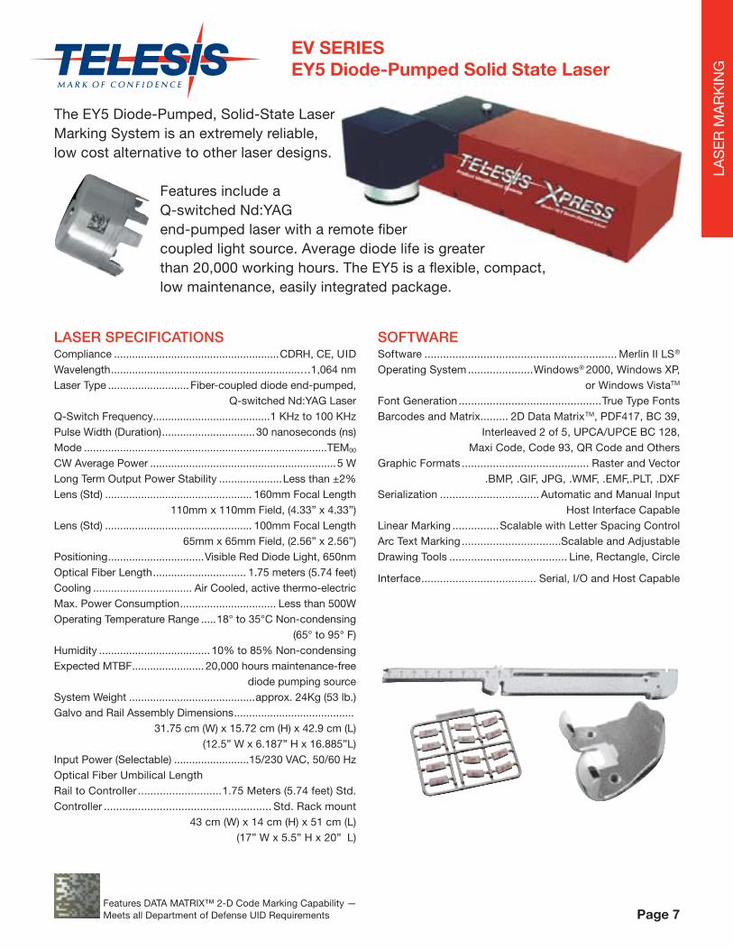
The EY5 Diode-Pumped, Solid-State Laser Marking System is an extremely reliable, low cost alternative to other laser designs.
Features include a Q-switched Nd:YAG end-pumped laser with a remote fi ber coupled light source. Average diode life is greater than 20,000 working hours. The EY5 is a fl exible, compact, low maintenance, easily integrated package.
LASER SPECIFICATIONSCompliance .......................................................CDRH, CE, UIDWavelength ...............................................................…1,064 nmLaser Type ........................... Fiber-coupled diode end-pumped, Q-switched Nd:YAG LaserQ-Switch Frequency .......................................1 KHz to 100 KHzPulse Width (Duration) ...............................30 nanoseconds (ns) Mode .................................................................................TEM00 CW Average Power ..............................................................5 WLong Term Output Power Stability .....................Less than ±2%Lens (Std) ................................................. 160mm Focal Length 110mm x 110mm Field, (4.33” x 4.33”)Lens (Std) ................................................. 100mm Focal Length 65mm x 65mm Field, (2.56” x 2.56”)Positioning ................................Visible Red Diode Light, 650nmOptical Fiber Length ............................... 1.75 meters (5.74 feet)Cooling ................................. Air Cooled, active thermo-electricMax. Power Consumption ................................ Less than 500WOperating Temperature Range .....18° to 35°C Non-condensing (65° to 95° F)Humidity ..................................... 10% to 85% Non-condensingExpected MTBF ........................ 20,000 hours maintenance-free
diode pumping sourceSystem Weight ..........................................approx. 24Kg (53 lb.)Galvo and Rail Assembly Dimensions ........................................
31.75 cm (W) x 15.72 cm (H) x 42.9 cm (L)(12.5” W x 6.187” H x 16.885”L)
Input Power (Selectable) .........................15/230 VAC, 50/60 HzOptical Fiber Umbilical LengthRail to Controller ...........................1.75 Meters (5.74 feet) Std.Controller ...................................................... Std. Rack mount
43 cm (W) x 14 cm (H) x 51 cm (L)(17” W x 5.5” H x 20” L)
SOFTWARESoftware .............................................................. Merlin II LS®
Operating System .....................Windows® 2000, Windows XP, or Windows VistaTM
Font Generation ..............................................True Type FontsBarcodes and Matrix......... 2D Data MatrixTM, PDF417, BC 39, Interleaved 2 of 5, UPCA/UPCE BC 128, Maxi Code, Code 93, QR Code and OthersGraphic Formats ......................................... Raster and Vector .BMP, .GIF, JPG, .WMF, .EMF,.PLT, .DXFSerialization ................................ Automatic and Manual Input Host Interface CapableLinear Marking ...............Scalable with Letter Spacing ControlArc Text Marking ................................Scalable and AdjustableDrawing Tools ...................................... Line, Rectangle, Circle
Interface ..................................... Serial, I/O and Host Capable
EV SERIESEY5 Diode-Pumped Solid State Laser
Page 7Features DATA MATRIX™ 2-D Code Marking Capability — Meets all Department of Defense UID Requirements
LAS
ER
MA
RK
ING

LASER SPECIFICATIONSCompliance .............................................................CDRH, CE, UIDWavelength .....................................................................…1,064 nm Laser Type .................................Fiber-coupled diode end-pumped, Q-switched Nd:YVO4 laserQ-Switch Frequency .............................................1 KHz to 100 KHzPulse Width (Duration) .....................................30 nanoseconds (ns) Mode ...................................................................................... TEM00 CW Average Power .....................................................................7WLong Term Output Power Stability ...........................Less than ±2%Lens (Std) ....................................................... 160mm Focal Length 110mm x 110mm Field, (4.33” x 4.33”)Lens (Std) ....................................................... 100mm Focal Length 65mm x 65mm Field, (2.56” x 2.56”)Positioning ......................................Visible Red Diode Light, 650nmOptical Fiber Length ..................................... 1.75 meters (5.74 feet)Cooling ....................................... Air Cooled, active thermo-electricMax. Power Consumption ...................................... Less than 500WOperating Temperature Range ..........18° to 35°C Non-condensing (65° to 95° F)Humidity ........................................... 10% to 85% Non-condensingExpected MTBF .............................. 20,000 hours maintenance-free
diode pumping sourceSystem Weight ................................................approx. 24Kg (53 lb.)Galvo and Rail Assembly Dimensions .............................................. 31.75 cm (W) x 15.72 cm (H) x 42.9 cm (L) (12.5” W x 6.187” H x 16.885”L)Input Power (selectable) ...............................115/230 VAC 50/60 Hz
SOFTWARESoftware ......................................................................Merlin II LS®
Operating System ............................ Windows® 2000, Windows XP,or Windows VistaTM
Font Generation ..................................................... True Type FontsBarcodes and Matrix ................2D Data MatrixTM, PDF417, BC 39,
Interleaved 2 of 5, UPCA/UPCE BC 128,Maxi Code, Code 93, QR Code and Others
Graphic Formats ................................................. Raster and Vector.BMP, .GIF, JPG, .WMF, .EMF, .PLT, .DXF
Serialization ....................................... Automatic and Manual InputHost Interface Capable
Linear Marking ...................... Scalable with Letter Spacing ControlArc Text Marking ....................................... Scalable and AdjustableDrawing Tools ................................. Line, Rectangle, Circle, EllipseInterface ............................................Serial, I/O and Host Capable
The EV7 is an advanced Nd:YVO4 , fi ber-coupled diode end-pumped laser marking system for applications requiring high beam quality and stability. The EV7 does an exceptional job of high speed marking on delicate and sensitive electronic components, thin metal foils and medical instruments. It’s also a very good choice for general purpose laser marking, scribing, trimming, and other material processing applications.
SYSTEM CONTROLLER
FEATURES• Reliable, long, maintenance-free performance• Compact size and modular construction• Remote, fi ber-coupled pumping diode• Exceptional beam quality and stable output power• Active (thermo-electrical) temperature control for the pumping diode and the laser crystal • Active AO Q-switching• Air cooling• Visible “red light” diode for dry run / part positioning• Large digital display for marker status, settings, and error condition monitoring• Standard 115/230VAC wall plug operation• DoD-compliant Unique Identifi cation (UID) marking
EV SERIESEV7 Diode-Pumped Solid State Laser
Page 8
The EV7 laser has an average diode life of greater than
20,000 working hours,
for outstanding reliability.
Features DATA MATRIX™ 2-D Code Marking Capability — Meets all Department of Defense UID Requirements
LAS
ER
MA
RK
ING
Optical Fiber Umbilical Length Rail to Controller .............................1.37 Meters (4.53 feet) Std.
Controller ............................................................Std. Rack mount43 cm (W) x 14 cm (H) x 51 cm (L), (17” W x 5.5” H x 20” L)

E-SERIESEV10/EV15 Vanadate Laser Marking Systems
DIMENSIONSEV10..........................75.9 cm (L) x 17.7 cm (W) x 18.0 cm (H) (29.9” L x 7.0” W x 7.1” H) EV15..........................68.0 cm (L) x 16.2 cm (W) x 19.1 cm (H) (26.8” L x 6.4” W x 7.5” H)Input Power (selectable).......................115/230 VAC 50/60 HzController Dimensions...................................Std. Rack Mount 42 cm (W) x 14 cm (H) x 50 cm (L) (16.5” W x 5.5” H x 19.5” L)Software................................................Merlin II LS® SoftwareOperating System........................Windows® 2000, XP, Vista™ Desktop PC (Std), Optional LaptopInterface.....................................Serial, I/O, and Host Capable
SPECIFICATIONSCompliance.....................................................CDRH, CE, UIDWavelength.................................................................1064 nmLaser Type.........................Fiber-coupled diode end-pumped, Q-switched Nd:YVO4 laserQ-Switch Frequency....................................10 kHz to 100 kHzPulse Width (Duration)...................................10 nanosecondsMode.............................................................................TEMooCW Average Power..........EV10 — 10 Watts EV15 — 15 WattsLong Term Output Power Stability...................Less than ± 2%Lens (Std)...............................................160mm Focal Length 110mm x 110mm Field (4.33” x 4.33”)Lens (Std)...............................................100mm Focal Length 65mm x 65mm Field (2.65” x 2.65”)Positioning............................Visible Red Diode Light (650 nm)Optical Fiber Length.............................1.75 meters (5.75 feet)Cooling................................Air-cooled, active thermo-electricMax. Power Consumption.......................Less than 500 WattsOperating Temperature Range..............................18° to 30° C Non-condensing (65° to 86° F)Humidity....................................10% to 85% Non-condensingExpected MTBF......................20,000 hours maintenance-free diode pumping sourceSystem Weight.....................................Approx. 30 kg (67 lbs.)
Page 9
The EV10 (10W) and EV15 (15W) vanadate laser marking systems are the latest advance in the E-series line of end pumped solid-state lasers from Telesis Technologies. While suitable for a wide range of general marking applications, the outstanding beam quality makes them uniquely capable among IR lasers for marking of high resolution graphics or fi ne text of 2D codes. With a short pulse width and high peak power these systems are ideal for challenging marking applications such as heat sensitive materials (including silicon), plastics, or thin foils. The narrow spot size and good depth of focus allow greater fl exibility, such as marking of curved surfaces, than achieved with fi ber lasers.
The EV10 and EV15 offer a diode MTBF of over 20,000 hours and essentially maintenance-free operation until diode replacement. The system is entirely air-cooled, avoiding the need for any external cooling system. The pumping diode is located in the controller and coupled by fi ber to the resonator and scanning head, allowing for a robust and compact design which is easy to integrate into a production environment.
Features DATA MATRIX™ 2-D Code Marking Capability — Meets all Department of Defense UID Requirements
LAS
ER
MA
RK
ING

LAS
ER
MA
RK
ING
The Telesis® EV4G is a fi ber-coupled, diode-pumped, solid state (DPSS), green wavelength laser marking system. The laser beam and Q-switched pulse characteristics are optimized for applications that require high beam quality and stability. In addition, the EV4G offers extra power and speed for precision marking and it is the ideal choice for laser marking, scribing, trimming, and other material processing applications. With average diode life of greater than 20,000 working hours, the EV4G offers the user “best-in-class” reliability. The robust mechanical and optical design of the Telesis EV4G enables operation in an industrial environment where shock, vibration, and dust are a concern.
EV4G Green Laser
FEATURES• Reliable, long-life, maintenance-free performance• Compact size and modular construction• Remote, fi ber-coupled pump diode• Exceptional beam quality and stable output power• Air cooling • Thermo-electrical temperature control of the laser
crystal and pump diode• Separate temperature controller for non-linear crystal • Active AO Q-switching • Large digital display for marker status, settings and
error condition monitoring• Standard 115/230VAC operation • DoD compliant Unique Identifi cation (UID) marking
Operation-enhancing options for the EV4G• Desktop computer or notebook computer with
powered cardbus-to-PCI expansion enclosure• Externally-mounted focus-fi nder diode• Tool post with manual hand crank for z-axis adjustment• Pushbutton station (start/abort)• I/O options:
– TTL via PCI-DIO24 card (kit #53920)– Opto-isolated via Merlin® DCIO module (kit #53928)– TMC090 controller (for auxiliary axes; additional I/O)
• Programmable X-, Y-, or Z-axis (auxiliary axis controller required)• Rotary drive fi xture (auxiliary axis controller required)• Vacuum system• Workstation/work area enclosures
Page 10
SPECIFICATIONS Compliance....................................................................CDRH Laser Type................................Fiber-coupled, diode pumped, Q-switched, Nd:YVO4Wavelength.............................................532 nanometers (nm)Average Power..............................................4 watts at 532nm Expected Diode Lifetime................Greater than 20,000 hoursLong Term Output Power Drift..........................Less than ±2%Maximum Power Consumption................Less than 600 wattsInput Power..........................................95 – 250 VAC, 6 amps, 50/60 Hz – single phaseSupply Voltage Fluctuation..........................±10%, maximum; clean ground lineOperating Temperature.......................18° – 30°C (65° – 86°F)Recommended Temperature...............20° – 25°C (68° – 77°F)Operating Relative Humidity.......10% – 85% non-condensingSpecifi cations measured at 20 kHz
LAS
ER
MA
RK
ING
EV4G Green Laser
LASER MARKING HEAD Dimensions (L x W x H)..............685.50 x 245.31 x 191.11mm (26.988 x 9.658 x 7.524”) Surrounding Envelope..............................840 x 305 x 250mm (33.0 x 12.0 x 10.0”)Mounting Weight Approximately........................25 kg (55 lbs.)Mounting Holes............................Six factory-tapped M5-0.80Field Resolution...............................16 bit (65535 data points)Galvanometer Repeatability............Less than 22 micro radianMarking Field Size..............Lens-dependent (see chart below)Fiber-Optic Cable Length.................................1.75m (5.73 ft.)Cooling........................ ........Air cooled, active thermo-electric
Page 11
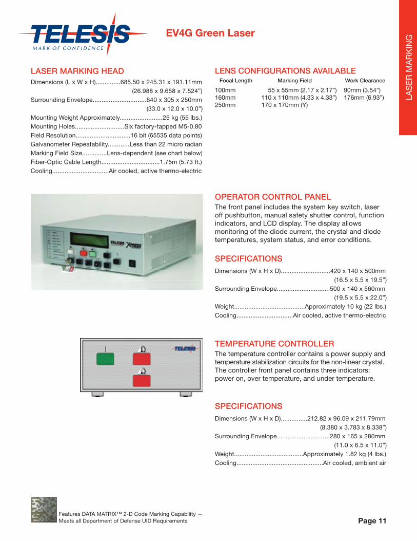
OPERATOR CONTROL PANELThe front panel includes the system key switch, laser off pushbutton, manual safety shutter control, function indicators, and LCD display. The display allows monitoring of the diode current, the crystal and diode temperatures, system status, and error conditions.
LENS CONFIGURATIONS AVAILABLE Focal Length Marking Field Work Clearance
100mm 55 x 55mm (2.17 x 2.17”) 90mm (3.54”)160mm 110 x 110mm (4.33 x 4.33”) 176mm (6.93”)250mm 170 x 170mm (Y)
SPECIFICATIONS Dimensions (W x H x D)............................420 x 140 x 500mm (16.5 x 5.5 x 19.5”)Surrounding Envelope..............................500 x 140 x 560mm (19.5 x 5.5 x 22.0”)Weight........................................Approximately 10 kg (22 lbs.)Cooling................................Air cooled, active thermo-electric
TEMPERATURE CONTROLLER The temperature controller contains a power supply and temperature stabilization circuits for the non-linear crystal. The controller front panel contains three indicators: power on, over temperature, and under temperature.
SPECIFICATIONS Dimensions (W x H x D)...............212.82 x 96.09 x 211.79mm (8.380 x 3.783 x 8.338”)Surrounding Envelope..............................280 x 165 x 280mm (11.0 x 6.5 x 11.0”)Weight.......................................Approximately 1.82 kg (4 lbs.)Cooling.................................................Air cooled, ambient air
Features DATA MATRIX™ 2-D Code Marking Capability — Meets all Department of Defense UID Requirements
LAS
ER
MA
RK
ING

LASER SPECIFICATIONSCompliance ..........................................................CDRH, CE, UID
Wavelength .....................................................................1,060nm
Laser Type ......................... Ytterbium Fiber Laser, Galvo Steered
Laser Source ..................... Diode-pumped, Fiber to Fiber, Pulsed
Pulse Repetition .............................................. 20 KHz to 125KHz
Average Power FQ10 ......................................................10 Watts
Average Power FQ20 .....................................................20 Watts
Long term Output Power ......................................<5% Instability
Peak Power FQ10 ...............................................................>4KW
Peak Power FQ20 ...............................................................>8KW
Beam Quality ..................................................................... M2 < 2
Fiber Length FQ10 ........................................ 5 Meters (16 ft) Std.
Fiber Length FQ20 ....................................... 3 Meters (9.8 ft) Std.
Optical Isolator FQ10 ..................................................... Standard
Optical Isolator FQ20 ..................................................... Standard
Positioning ..................................Visible Red Diode Light. 636nm
Innovative, compact and fl exible F-SERIES Fiber Lasers are perfectly suited for markingapplications that require 24/7 “set and forget”, unattended operation.
Select the 10W FQ10 for low to medium speed applications and the 20W FQ20 when higher power/faster process speeds are required. The FQ20 features upgraded power. Both lasers offer the additional long-term safeguard of built-in, polarization/optical isolators.
Marking Speed .........................Raster = 300 CPS; Vector>500 CPS (application dependent)
Input Power ........................ Selectable 115VAC / 230VAC, 50/60HZ
Cooling ............................................................Air Cooled, Fan/Filter (no water cooling required)
Operating Temperature Range ..........10o to 42 o C Non-Condensing (50 o F to 107 o F)
Expected MTTF (Diode) ........................Greater than 100,000 hours
Example — Laser markingon Coated Label Stock
Customized Part HandlingOptions Available
F-SERIES FQ10/FQ20 Fiber Lasers
Page 12Features DATA MATRIX™ 2-D Code Marking Capability — Meets all Department of Defense UID Requirements
LAS
ER
MA
RK
ING

DIMENSIONSFQ10 Marking Head ....................51.0 (L) x 12.7 (W) x 14.0 (H) cm
20.1” (L) x 5.0” (W) x 5.5” (H)Weight 6.82 kg (15 lbs.)
FQ10 Laser Controller ................................ Standard Rack Mount 42.5 (W) x 13.7 (H) x 50.8 (D) cm
16.7” (W) x 5.4” (H) x 20.0” (D)Weight 15 kg (33 lbs.)
FQ20 Marking Head ....................51.0 (L) x 12.7 (W) x 14.0 (H) cm 20.1” (L) x 5.0” (W) x 5.5” (H)
Weight 6.82 kg (15 lbs.)
FQ20 Laser Controller ................................ Standard Rack Mount 42.5 (W) x 13.7 (H) x 50.8 (D) cm
16.7” (W) x 5.4” (H) x 20.0” (D)Weight 15 kg (33 lbs.)
Powered by 110/230VAC with no water-cooling requirements, these F-Series units are extremely dependable over a long life, and are backed by a full TWO-YEAR factory warranty.
“All of your employees seem to be willing and able to give that “little bit extra” to make everything go right.The laser marking equipment you have supplied to us thus far has been totally reliable and continues to perform fl awlessly, helping Federal-Mogul Corporation reduce costs as it continues to improve product quality. I look forward to a continued relationship with the people I consider my “friends” at Telesis Technologies.”
Best Regards,
Ed Reinemeyer Process Engineer, Federal-Mogul Corporation
SOFTWARESoftware ....................................................................Merlin® II LS
Operating System ......................... Windows® 2000, Windows XP, or Windows VistaTM
Font Generation ...................................................True Type Fonts
Barcodes and Matrix........... 2D Data Matrix TM, PDF417, BC 39, Interleaved 2 of 5, UPCA/UPCE BC 128, Maxi Code, Code 93, QR Code and Others
Graphic Formats ..............................................Raster and Vector, BMP, .GIF, JPG, .WMF, .EMF,.PLT, .DXF
Serialization ............................ Automatic and Manual Input Host Interface Capable
Linear Marking ....................Scalable with Letter Spacing Control
Arc Text Marking .................................... Scalable and Adjustable
Drawing Tools ....................................Line, Rectangle, Arc, Circle
Interface ...........................................Serial, I/O and Host capable
Power Monitoring ....... Self-Calibrating, Output Power Feedback and Auto Adjustment
LENS CONFIGURATIONS AVAILABLE Focal Length Marking Field Work Clearance
100mm 45mm x 45mm (1.8” x 1.8”) 97mm (3.82”)
160mm 90mm x 90mm (3.5” x 3.5”) 176mm (6.93”)
163mm 110mm x 110mm (4.3” x 4.3”) 185mm (7.28”)
254mm 155mm x 155mm (6.1” x 6.1”) 296mm (11.65”)
* 330mm 215mm x 215mm (8.4” x 8.4”) 387mm (15.23”)
* 420mm 275mm x 275mm (10.8” x 10.8”) 493mm (19.40”)
* Application dependent
Example
Laser marking on Coated Label Stock
F-SERIES FQ10/FQ20 Fiber Lasers
Page 13Features DATA MATRIX™ 2-D Code Marking Capability — Meets all Department of Defense UID Requirements
LAS
ER
MA
RK
ING

FEATURES• Reliable, maintenance free performance
• Compact size and modular construction
• Requires a fraction of normal power consumption for optimum performance
• Exceptional beam quality and stable output power
• Active AO Q-Switching
• Output laser beam delivery via fi ber optic cable
• Sealed marking head prevents dust penetration into the optical compartment
• Two scan head confi guration for doubling marking throughput
• Two visible “red light” diodes for dry run / positioning for each scan head
• Air cooled
• Display monitors the actual laser power
• Display monitors worked hours
• Standard 115/230VAC wall plug operation
• DoD-compliant Unique Identifi cation (UID) marking
The FQ20DH from TELESIS features an advanced, dual-scan marking head, based on our successful Pulsed-Fiber Laser platform. Capable of extremely high-speed, high quality simultaneous, duplicate marking on two surfaces, it offers lower operation costs along with increased production and handling effi ciencies. In addition to marking, the FQ20D is an excellent choice for scribing, trimming and a variety of material processing applications.
LASER CONTROLLER SPECIFICATIONS
Dimensions (W x H x L) ...........................16.74” x 5.25” x 20.0”
Weight .................................................. approx. 15.5 kg (34 lbs)
Input Power (selectable) ..........................115/230VAC 50/60 Hz
GENERAL SPECIFICATIONSCompliance .......................................................CDRH, CE, UID
Wavelength ..................................................1,060 nm (+/-10nm)
Laser Type ...................ytterbium doped Q-Switched fi ber laser
Q-Switch Frequency ........................................ 20KHZ to 80KHz
Average power per scan head....................................................10 Watts (combined 20 Watts)
Beam quality ....................................................................M2 < 2
Long term power stability .................................... less than ±5%
Positioning .......................................................... two red diodes
Fiber optic cable length ................................. 3 meters (9.8 feet)
Cooling .......................................................................Air cooled
Max. Power Consumption ..................................less than 550W
Operating Range ................................10° to 35°C (50° to 95°F)
Humidity ......................................10% to 85% non-condensing
Expected MTBF (Diode) ................. Greater than 100,000 hours
Shipping weight(for 160mm lenses) .................................. approx. 35 kg (77 lbs)
LASER MARKING HEAD SPECIFICATIONS
Dimensions (L x W x H) ...........................20.0” x 13.9” x 5.486”
Mounting Weight(with 160mm lenses) ................................. approx. 16 kg (35lbs)
Mounting Holes ......................................................... six M5-0.8
FQ20DH Fiber Laser
Page 14Features DATA MATRIX™ 2-D Code Marking Capability — Meets all Department of Defense UID Requirements
LAS
ER
MA
RK
ING

SY50 Diode-Pumped Solid State Laser
LENS CONFIGURATIONS AVAILABLE
Focal Length Marking Field Work Clearance
100mm 45mm x 45mm (1.8” x 1.8”) 97mm (3.82”)
160mm 90mm x 90mm (3.5” x 3.5”) 176mm (6.93”)
163mm 110mm x 110mm (4.3” x 4.3”) 185mm (7.28”)
254mm 155mm x 155mm (6.1” x 6.1”) 296mm (11.65”)
* 330mm 215mm x 215mm (8.4” x 8.4”) 387mm (15.23”)
* 420mm 275mm x 275mm (10.8” x 10.8”) 493mm (19.40”)
* Application dependent
FEATURES• Unique, Three Rail Design for Easy Alignment, Increased Power and Thermal Stability• Lightweight, Dust Sealed Rail Cover • Fixed Beam Expander• Safety Shutter, Co-Axial Red Diode Pointer and Emission Light for Simple Operation
DIMENSIONSLaser ............................................... 8” W x 8” H x 33” L
Water Chiller System ......... 12.6” W x 23.5” H x 20.9” D
Umbilical Length ..............................6 Feet [detachable]
LASER CONTROLLER SYSTEM FEATURES• Self-Contained Remote DI Water System / DI and
Particle Filters (No External Chiller Required)
• Flow and Temperature Sensors
• Keyswitch and E-Stop with Manual Shutter Control
• 1st Pulse Suppression Circuitry
• System PC, Mounted directly in control cabinet
• Alternate electrical box for mounting/wiring peripheral components
The SY50 Diode-Pumped Solid State Laser is confi gured for high precision, high speed marking. Features include high quality beam performance and low maintenance. It’s an economical choice for marking titanium and other high strength alloys and medical implants.
SPECIFICATIONSCompliance ..................................................... CDRH, CE, UIDType .................................................. Nd: Diode-pumped YAGWavelength .............................................................. 1,064 NmAverage Power ...........................................................50 WattsMode .................................................................... Q-Switched Q-Switch Frequency ............................................. 2 to 50 KHzMarking Speed .............02 to 197 in/sec (.5 to 5000 mm/sec.)Marking Fields ............................................. Several AvailableElectrical ............................Single phase, 110V, 60Hz nominalTotal System Power Consumption ......2.2 kW input AC PowerInternal DI Water .......... Requires (1.5) gallons, steam distilledExternal Cooling Water ........................................ Not required
Page 15Features DATA MATRIX™ 2-D Code Marking Capability — Meets all Department of Defense UID Requirements
LAS
ER
MA
RK
ING

SPECIFICATIONSCompliance ..................................................... CDRH, CE, UIDType ...................................................Nd: Lamp-pumped YAGWavelength .............................................................. 1,064 NmAverage Power .........................................................100 WattsMode .......................... Q-Switched or CW (Continuous Wave)Q-Switch Frequency ...........................................0 to 100 KHzMarking Speed...................02 to 197 in/sec(.5 to 5000 mm/sec.)Marking Fields ............................................. Several AvailableElectrical ....................3 phase/3 wire, 230V, 50-60Hz nominalTotal System Power Consumption ..............................7.5 KVAInternal DI Water ............. Requires (5) gallons, steam distilledExternal Cooling Water ..............5 gallons/min. (19 liters/min.) 50º F - 65º F, (10º- 18º C)
LASER CONTROLLER/DI WATER CABINET FEATURES
• Compact, “All in One Design” Mounted on Casters
• Slide-out DI Water System / DI and Particle Filters
• Flow, Temperature and DI Sensors
• Keyswitch and E-Stop with Manual Shutter Control
• 1st Pulse Suppression Circuitry
DIMENSIONS
Laser .............................................. 8” W x 9” H x 56” L
Laser Power/DI Water Supply Cabinet .......................... 24” W x 27” H x 30” D
Umbilical Length ........................... 10 Feet [detachable]
All Marking Head Components and AssemblyWarranted for One Year
LENS CONFIGURATIONS AVAILABLE
Focal Length Marking Field Work Clearance
100mm 45mm x 45mm (1.8” x 1.8”) 97mm (3.82”)
160mm 90mm x 90mm (3.5” x 3.5”) 176mm (6.93”)
163mm 110mm x 110mm (4.3” x 4.3”) 185mm (7.28”)
254mm 155mm x 155mm (6.1” x 6.1”) 296mm (11.65”)
* 330mm 215mm x 215mm (8.4” x 8.4”) 387mm (15.23”)
* 420mm 275mm x 275mm (10.8” x 10.8”) 493mm (19.40”)
* Application dependent
FEATURES• Unique, Straight INVAR Rail Design for Easy Alignment, Increased Power and Thermal Stability
• Lightweight, Dust Sealed Rail Cover features “Hideaway Handles” for easy access
• Fixed Beam Expander
• Safety Shutter, Co-Axial Red Diode Pointer and Emission Light for Simple Operation
For the Ultimate in High Speed, High Quality Product Identifi cation, the Lamp-Pumped LY100 is designed for hard surface treatments. It’s the powerful, reliable choice for deep engraved, to shallow, annealed marking on titanium and other high strength alloys, medical implants and hard plastics.
LY100Lamp-Pumped Solid State Laser
Page 16Features DATA MATRIX™ 2-D Code Marking Capability — Meets all Department of Defense UID Requirements
LAS
ER
MA
RK
ING

The Telesis CO-Series Lasers are optimized to provide extremely high-speed operation, through the use of a reliable galvo scanner using self-diagnostic servo drivers. The reliable RF-excited CO2 tube assures a long life cycle and virtually maintenance-free operation. Due to its compact size and modular construction, the CO-Series Laser Marker can fi t where it’s needed on the plant fl oor.
FEATURES• The CO-Series lasers are perfect for
“Mark-on-the-fl y” linear and circular movements
• Standard 100 – 240VAC, 50 – 60Hz operation
• Easy-to-use Merlin® II Visual Design Software
• Support of linear and 2-D bar codes including the QR code
• DoD compliant Unique Identifi cation (UID) marking
• Multi-language support
• Available in 3 different power levels, 10W model CO10, 30W model CO30 and 50W model CO50
CO-SERIESCO2 Lasers
Flexibility and ease-of-use: CO-Series laser options
• Tool post with manual hand crank for Z-axis adjustment
• Pushbutton station (start/abort)
• I/O options:– TTL via PCI-DIO24 card (kit #53920)– Opto-isolated via Merlin® DCIO module (kit #53928)– Auxiliary controller (for auxiliary axes; additional I/O)
• Programmable X-, Y-, or Z-axis (auxiliary controller required)
• Rotary drive fi xture
• Vacuum system
• Workstation/work area enclosures
• Quadrature shaft encoder
• TTL level part position detector
SPECIFICATIONSLaser Type...........10W, 30W, 50W, air cooled RF-excited CO2 laser at 10,6µm wavelength (9.3µm option is available) Marking Head Size (H x W x L)................................................ 781.0 x 184.3 x 206.5mm (10W) (30.75 x 7.26 x 8.13”) 861.3 x 206.9 x 226.8mm (30W) (33.91 x 8.14 x 8.93”) 1143.5 x 141.6 x 207.8mm (50W) (45.02 x 5.75 x 8.18”)
Controller Size (H x W x L)........................ 570 x 419 x 176mm (22.4 x 16.5 x 6.9”)
Marking Head Weight.........................13.8 kg (30.4 lbs.)(10W) 26.3 kg (58 lbs.)(30W) 25.45 kg (56 lbs.)(50W)
Controller Weight .........................................14.3 kg (31.5 lbs.)Input................................................100 – 240 VAC, 50 – 60HzOperating Temperature.............................................16 – 35°C
LENS CONFIGURATIONS AVAILABLE Focal Length Marking Field Work Clearance
75mm 50 x 50mm (1.97 x 1.97”) 54mm (2.13”) 100mm 70 x 70mm (2.76 x 2.76”) 81mm (3.19”) 150mm 100 x 100mm (3.94 x 3.94”) 131mm (5.16”) 200mm 140 x 140mm (5.51 x 5.51”) 183mm (7.20”) Other lens sizes available
MARKING SPEED• Up to 152 m/minute (500 ft./minute) line speed for
“Mark-on-the-fl y” applications*• 400 characters/second (multiline marking is supported)*
* Character marking speeds and production line speeds depend on material, character size and the desired marking quality.
Page 17Features DATA MATRIX™ 2-D Code Marking Capability — Meets all Department of Defense UID Requirements
LAS
ER
MA
RK
ING

LASER SOFTWARE
This powerful Merlin® II Visual Design Software is capable of driving any of the core Telesis Laser Products. Each system is shipped with a fully functioning version of the Software (on CD), that allows off-line program development.
Main Programming Screen
TELESIS LASER SOFTWARE FEATURES:• Specially Designed by TELESIS – based on Windows® 2000,Windows XP, or Windows VistaTM
• Import a wide range of Graphic Formats including DXF from AutoCAD™, WINDOWS® Bitmaps, True Type Fonts as Vector or Raster Files
• Supports 4 Axis Movement (XYZ & Rotary)
• Highlight, click and mark!
COMPUTER REQUIREMENTS:• Pentium® III 128 Mb RAM (minimum)
• Multi-gigabyte HDD
• Video, Sound Card
• CD-ROM and 3.5” Floppy Disk Drive
• SVGA Monitor, Mouse and Keyboard
Bar Code Editor
Raster Profi le
Vector Profi le
On Line Help
Window Overview
Page 18
LAS
ER
MA
RK
ING

FQ20
1070nm wavelength, air-cooled, single phase, Q-switched, 20 Watt Yb
fi ber laser marker (Will provide shorter cycle
times than FQ10.)
Good choice for surface and deep marking
of some metals. (Sensitive to back refl ection.
Not recommended for copper, brass or any other highly
refl ective or polished metals.)
Good choice for marking many plastics and label
materials. (Some surface melting can occur due to
long pulse width.)
Capable of deep marking of silicon.
Cannot mark wood. Can mark some other
organic materials.
Can mark metals, glass and other materials using
chemical marking.
Can mark high quality graphics on some metals.
Optional
LASER SYSTEMS/APPLICATIONS
Marking metals
Marking plastics and label materials (3M, Tesa, etc.)
Marking silicon
Marking organic materials
Chemical marking
Marking high quality graphics
Workstation
FQ10
1070nm wavelength, air-cooled, single phase, Q-switched, 10 Watt Yb
fi ber laser marker
Good choice for surface and deep marking
of some metals. (Sensitive to back refl ection.
Not recommended for copper, brass or any other highly
refl ective or polished metals.)
Good choice for marking many plastics and label
materials. (Some surface melting can occur due to
long pulse width.)
Capable of deep marking of silicon.
Cannot mark wood. Can mark some other
organic materials.
Can mark metals, glass and other materials using
chemical marking.
Can mark high quality graphics on some metals.
Optional
FQ20DH
1070nm wavelength, air-cooled, single phase,
Q-switched, dual scan head, 10 Watt per scanhead, Yb fi ber laser marker
Good choice for surface and deep marking
of some metals. (Sensitive to back refl ection.
Not recommended for copper, brass or any other highly
refl ective or polished metals.)
Good choice for marking many plastics and label
materials. (Some surface melting can occur due to
long pulse width.)
Capable of deep marking of silicon.
Cannot mark wood. Can mark some other
organic materials.
Can mark metals, glass and other materials using
chemical marking.
Can mark high quality graphics on some metals.
Optional
LASER MARKING SYSTEMSELECTION GUIDE
Page 19
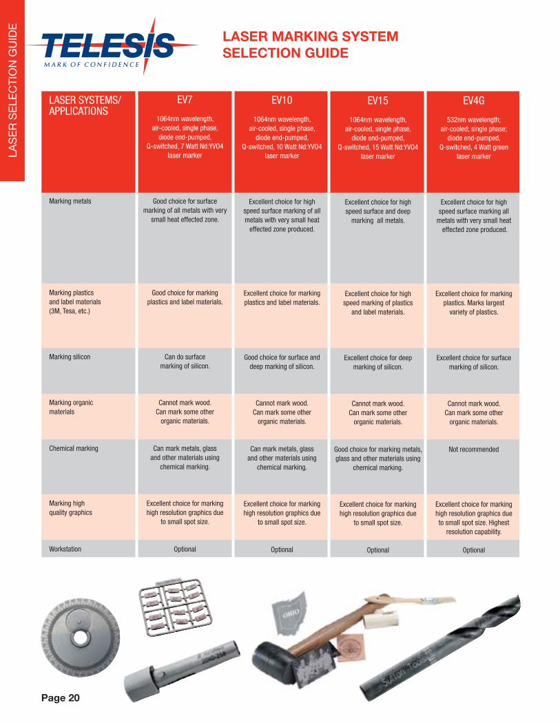
EY5
1064nm wavelength, air-cooled, single phase,
diode end-pumped, Q-switched, 5 Watt Nd:YAG
laser marker
Good choice for surface and deep marking all metals.
Good choice for marking plastics and label materials.
Capable of deep marking of silicon.
Cannot mark wood. Can mark some other
organic materials.
Can mark metals, glass and other materials using
chemical marking.
Excellent choice for marking high resolution graphics due
to small spot size.
OptionalLA
SE
R S
ELE
CTI
ON
GU
IDE
Page 20
EV10
1064nm wavelength, air-cooled, single phase,
diode end-pumped, Q-switched, 10 Watt Nd:YVO4
laser marker
Excellent choice for high speed surface marking of all metals with very small heat
effected zone produced.
Excellent choice for marking plastics and label materials.
Good choice for surface and deep marking of silicon.
Cannot mark wood. Can mark some other
organic materials.
Can mark metals, glass and other materials using
chemical marking.
Excellent choice for marking high resolution graphics due
to small spot size.
Optional
EV7
1064nm wavelength, air-cooled, single phase,
diode end-pumped, Q-switched, 7 Watt Nd:YVO4
laser marker
Good choice for surface marking of all metals with very
small heat effected zone.
Good choice for marking plastics and label materials.
Can do surface marking of silicon.
Cannot mark wood. Can mark some other
organic materials.
Can mark metals, glass and other materials using
chemical marking.
Excellent choice for marking high resolution graphics due
to small spot size.
Optional
EV15
1064nm wavelength, air-cooled, single phase,
diode end-pumped, Q-switched, 15 Watt Nd:YVO4
laser marker
Excellent choice for high speed surface and deep
marking all metals.
Excellent choice for high speed marking of plastics
and label materials.
Excellent choice for deep marking of silicon.
Cannot mark wood. Can mark some other
organic materials.
Good choice for marking metals, glass and other materials using
chemical marking.
Excellent choice for marking high resolution graphics due
to small spot size.
Optional
EV4G
532nm wavelength; air-cooled; single phase;
diode end-pumped, Q-switched, 4 Watt green
laser marker
Excellent choice for high speed surface marking all
metals with very small heat effected zone produced.
Excellent choice for marking plastics. Marks largest
variety of plastics.
Excellent choice for surface marking of silicon.
Cannot mark wood. Can mark some other
organic materials.
Not recommended
Excellent choice for marking high resolution graphics due to small spot size. Highest
resolution capability.
Optional
LAS
ER
SE
LEC
TIO
N G
UID
E
LASER SYSTEMS/APPLICATIONS
Marking metals
Marking plastics and label materials (3M, Tesa, etc.)
Marking silicon
Marking organic materials
Chemical marking
Marking high quality graphics
Workstation
LASER MARKING SYSTEMSELECTION GUIDE

For all applications, it is highly recommended
that samples be sent to Telesis for
qualifi cation and testing purposes.
Page 21
CO10
10,600nm wavelength, air- cooled, single phase,
RF excited, 10W CO2 laser marker
Can mark some anodized metal surfaces.
Excellent choice for high speed marking plastics and
some label materials.
Not recommended
Excellent choice for marking wood and other
organic materials.
Good choice for marking metals, glass
and other materials using chemical marking
Can mark high quality graphics on plastics and
on some anodized metal surfaces.
Optional
LY100
1064nm wavelength, water-cooled, three phase,
lamp pumped, Q-switched, 90W Nd:YAG
laser marker
Good choice for high speed surface and deep
marking of metals. Provides the shortest cycle times
for deep marking.
Good choice for marking plastics and label materials.
Can do deep marking and cutting of silicon.
Cannot mark wood. Can mark some other
organic materials.
Good choice for marking metals, glass
and other materials using chemical marking
Can mark high quality graphics on some metals.
Optional
CO30
10,600nm wavelength, air-cooled, single phase,
RF excited, 30W CO2 laser marker
(Will provide shorter cycle times than CO10.)
Can mark anodized metal surfaces. With short focal
length lenses, can mark some non-plated metal surfaces.
Excellent choice for high speed marking of plastics and
some label materials.
Not recommended
Excellent choice for marking wood and other
organic materials.
Excellent choice for marking metals, glass
and other materials using chemical marking.
Can mark high quality graphics on plastics and
on some anodized metal surfaces.
Optional
CO50
10,600nm wavelength, air-cooled, single phase,
RF excited, 50W CO2 laser marker
(Will provide shorter cycle times than CO30.)
Can mark anodized metal surfaces. With short focal
length lenses, can mark some non-plated metal surfaces.
Excellent choice for high speed marking plastics and
some label materials.
Not recommended
Excellent choice for marking wood and other
organic materials.
Excellent choice for marking metals, glass
and other materials using chemical marking.
Can mark high quality graphics on plastics and
on some anodized metal surfaces.
Optional LA
SE
R S
ELE
CTI
ON
GU
IDE
SY50
1064nm wavelength, water-cooled, single phase,
diode side pumped,Q-switched, 50W Nd:YAG
laser marker
Good choice for high speed surface and deep
marking of metals.
Good choice for marking plastics and label materials.
Can do deep marking and cutting of silicon.
Cannot mark wood. Can mark some other
organic materials.
Good choice for marking metals, glass
and other materials using chemical marking.
Not recommended
Optional

FEATURES• Large 6” x 12” (152 x 304mm) marking window
• Unique rigid positioning drive features robotic technology
• Marks a wide range of materials from soft plastics to hardened steel — up to Rc60
• Dot density up to 200 dots per inch (79 per centimeter)
• Choice of Interchangable Marking Pin Types for depths from .001” – .018” (.02 – .45mm)
• Pin travel accommodates surface irregularities to .25” (6mm)
• Compact, self-contained TMC470 Controller with integral display and keyboard – no PC required
• RS232 or TCPIP Host interface to download text to individual fi elds or call up entire patterns
• Automatically generates serial numbers, time, date and shift codes
• Easily interfaced to PLCs (Programmable Logic Controllers)
• Pattern backup via USB port
• Stores up to 200 marking patterns (fi les)
TMP6100/470PINSTAMP® SINGLE PIN MARKING SYSTEM
The TMP6100 is the most versatile PINSTAMP® Marking Head. It is easily integrated into either on or off-line
applications. Since the marking pin can be positioned anywhere in the generous 6” x 12” (152 x 304mm)
marking window, the TMP6100 can mark any character height, style or number of lines desired. Its robotic
design allows clear access to the marking window for loading and unloading of parts.
OPTIONAL ACCESSORIES• Rotary fi xtures for marking circumferences
of cylindrical parts
• Marking head mounting posts, including programmable Z-axis version
• Logo/Font design Software Package for design of custom fonts or simple logos
• Powerful Windows-based Merlin® III software(available in early 2009)
“We recommend Telesis hardware to our clients because we believe it is the best marking equipment available. The success of our software business depends on high quality 2D Data MatrixTM dot peen marks and Telesis consistently delivers quality marks – every day – every time!”
Chuck Stewart, Stewart Technologies Inc.
The TMP6100/470 contains Data Matrix® 2-D code marking capability, meeting all US Department of Defense UID requirements and other industry standards.Page 22
PIN
STA
MP
® M
AR
KIIN
G

TMC470MARKING SYSTEM CONTROLLER
VISUAL DESIGN SOFTWARE
Telesis’ pow-erful WIN 32 Merlin®III Visual Design Software with its state-of-the ar t graphical user in-interface, makes marking pattern design quick and easy.
“WYSIWYG” (what you see is what you get)interface providesa to-scale image of the pattern as it’s created. Just “click & drag” for immediate adjustment to fi eld size, location or orientation. Pattern Wizard Mode makes simple pattern design a snap even for the computer novice.
Marking “tools” available include
text (at any angle), arc text,
rectangles, circles, ellipses and lines.
Multiple fi elds can be grouped and saved as ablock to form a logo, or import logos via DXF
CAD fi les.Non-printable
fi elds clearly show the graphical
representation of the part being marked. Use the convenient, “GO TO” command to avoid
obstacles within the marking window.
FEATURES• Fully self-contained – no PC required
• Easy-to-use menu design for pattern design and access
• Ethernet port for TCP/IP commmunications
• Durable membrane keyboard
• Pattern backup via USB port
• Stores up to 200 marking patterns locally
• One RS232/485 and one RS232 serial port and discrete I/O capabilities with spare I/O available for customer-specifi c needs
• Optional internal board to control third and fourth axis (Z and rotary) – no seperate driver required
• Optional panel-mount kit for panel mounting in NEMA/IP rated enclosures
• Conforms to all European Community (CE) norms• Operates on 100 – 130 VAC or 200 – 250 VAC,
50 – 60 Hz power
Page 23
PIN
STA
MP
® M
AR
KIIN
G

The TMP1700/420 is the lowest cost PINSTAMP® Marking System. The rugged TMP1700 marking head features a compact, 1-1/2” x 2-1/2” (38.1 x 63.5mm)
window, and marking speeds up to six characters per second. It’s an excellent choice for many factory-automated or on-line processes. The TMP1700/090
includes the TMP1700 Marking Head, but features our WIN 32 Merlin®II Visual Design Software, providing a state-of-the-art graphical user interface.
Page 24
TMP1700/420 and TMP1700/090PINSTAMP® SINGLE PIN MARKING SYSTEMS
A protective shutter assembly shields the TMP1700 marking head from
liquid and solid contaminants.
FEATURES• 1-1/2” x 2-1/2” (38.1 x 63.5mm) Marking Window
• Rugged, low-maintenance X/Y platform
• Compact Marking Head — approximately 6.6” x 6.2” x 4.7” (168 x 158 x 120mm)
• Marks a wide range of materials from soft plastics to hardened steel — up to Rc60
• Shutter assembly protects marking head from solid and liquid contaminants
• Compact, convenient TMC420 Controller with rubber keyboard and 4-line LED Display — no PC required (see page 27)
• Dot density up to 200 dots per inch (79 per centimeter)
• Choice of Interchangeable Marking Pin Types for depths from .001” - .018” (.03 - .45mm)
• Pin travel accommodates surface irregularities to .25” (6mm)
• Automatically generates serial numbers, time, date and shift codes
• Stores up to 75 marking patterns
• Easily interfaced to PLCs (Programmable Logic Controllers) and Host Computers
OPTIONALACCESSORIES• TMP1700/090 System includes the TMC090 Controller and Merlin®II Visual Design Software in lieu of TMC420 Controller (see page 23)
• Rotary fi xtures for marking circumferences of cylindrical parts
• Marking head mounting post including programmable Z-axis version
• Panel-mount and IP/NEMA Rated Controllers (see page 27)
• Logo/Font design software package for design of custom fonts or logos
• PC-Based Upgrade Utility available FREE from www.telesis.com for easy software upgrade
• PC-Based Pattern Back-up Utility available FREE from www.telesis.com
Compact TMC420 Controllerfeatures 4-line LCD Display —
no PC required.
The TMP1700/420 contains Data Matrix® 2-D code marking capability, meeting all US Department of Defense UID requirements and other industry standards.
PIN
STA
MP
® M
AR
KIIN
G

Page 25
The TMP4210/420 is an extremely lightweight, hand-held, single pin marker satisfying a wide range of portable marking applications. Its robust rack-and-pinion design and compact envelope also make it the right choice for many high production, on-line applications.
OPTIONAL ACCESSORIES
• Cable Balancer Attachment Bracket
• Marking Head Standoff V-Blocks for Marking the Circumference of Cylindrical Parts
• Bar Code Scanner for automatic data entry
• Logo-Font design software package for design of custom fonts or logos
• PC-Based Upgrade Utility available FREE from www.telesis.com for easy software upgrade
• PC-Based Pattern (marking fi le) Back-up Utility available FREE from www.telesis.com
FEATURES
• Simple, Easy to Use Single Pin Design
• Compact and Ergonomic; Weighs about 2.0kg (4.4 pounds)
• Available with 25S or 150SA Marking Pin
• 50 x 13mm (2” x .5”) Marking Window
• Economically Priced
• Marks up to 3.5 3mm (1/8”) High Characters per Second
• Utilizes Same Rugged Rack-and-Pinion X/Y Platform as Field-Proven TMM4200
• Detachable Electronics Cable for Improved Serviceability
• Teamed with Reliable, Self-Contained TMC420 Controller (see page 27)
• Also Available Without Handle and Stand-Off for Fixtured Applications
TMP4210/420PINSTAMP® SINGLE PIN MARKING SYSTEM
Compact TMC420 Controller features4-line LCD Display — no PC required.
The TMP4210/420 contains Data Matrix® 2-D code marking capability, meeting all US Department of Defense UID requirements and other industry standards.
PIN
STA
MP
® M
AR
KIIN
G

Page 26
TMP3200/420 and TMP3200/090PINSTAMP® SINGLE PIN MARKING SYSTEMS
OPTIONAL ACCESSORIES• TMP3200/090 System includes the TMC090 Controller and Merlin®II Visual Design Software in lieu of TMC420 Controller (see page 23)
• Rotary fi xtures for marking circumferences of cylindrical parts
• Marking head mounting post including programmable Z-axis version
• Panel-mount and IP/NEMA-Rated Controllers (see page 27)
• Logo/Font design software package for design of custom fonts or logos
• PC-Based Upgrade Utility available FREE from www.telesis.com for easy software upgrade
• PC-Based Pattern Back-up Utility available FREE from www.telesis.com
FEATURES• 4” x 6” (100 x 150mm) Marking Window
• Belt-driven, dual rail X/Y mechanism with superior wear characteristics
• Patented fl oating pin technology accommo- dates surface irregularities of up to .25” (6mm)
• Marks a wide range of materials from soft plastics to hardened steel — up to Rc60
• Choice of pin sizes for marking depths from .001” - .018” (.03 - .45mm)
• Compact, convenient TMC420 controller with rubber keyboard and 4-line LCD display — no PC required (see page 27)
• Automatically generates serial numbers, date, time and shift codes
• Stores up to 75 marking patterns
• Easily interfaced to PLCs (Programmable Logic Controllers) and Host Computers
• Dot density up to 200 dots per inch (79 per centimeter)
The TMP3200/420 Single Pin Marking System features a large 4” x 6” (100 x 150mm) markingwindow, and marking speeds up to six characters per second. Well suited for both bench top and factory-automated applications, its simple, yet robust belt-driven dual rail, X/Y platform yields high quality characters and low maintenance operation. The TMP3200/090 includes the TMP3200 Marking Head, plus our WIN 32 Merlin®II Visual Design Software, with state-of-the-art graphical user interface.
A protective shutter assembly shields the TMP3200 marking head from liquid and solid contaminants.
Compact TMC420 Controller features4-line LCD Display —no PC required.
The TMP3200/420 contains Data Matrix® 2-D code marking capability, meeting all US Department of Defense UID requirements and other industry standards.
PIN
STA
MP
® M
AR
KIIN
G

Page 27
TMC420MARKING SYSTEM CONTROLLER
The TMC420 is a versatile, compact system controller that can be used with a wide range of Telesis Marking
Heads. The TMC420 is fully self-contained and requires no Personal Computer. Other features include a
4-line LCD display and rugged membrane keyboard. With an RS232/485 serial port and eight discrete inputs/
outputs, the TMC420 is easily integrated with factory automated applications.
The TMC420P is a panel-mount version designed specifi cally for
mounting in industrial enclosures.
The TMC420N is a NEMA 12 (IP55) rated version for wall mounting or table top use.
FEATURES• No PC required
• Three standard character fonts
• Automatic serialization, date coding and shift coding
• Four-line LCD display and rugged, sealed keyboard
• User-friendly pattern design software and prompted, interactive data entry
• Stores up to 75 marking patterns
• Extremely compact 12-1/2” W x 8” D x 2.8” H (317 x 203 x 71mm) envelope
• 12-24 VDC “Start Print,” “Abort,”, “Ready” and “Done” I/O signals
• Up to 15 different marking patterns remotely selectable via 12-24 VDC discrete inputs
• RS232 Host/Scanner Interface to download text to individual fi elds or call up entire patterns
• Up to 31 controllers can be networked to a single host
• “Start Print” and “Abort Print” signals from a simple contact closure
• Operates on 100-130 VAC or 200-250 VAC, 50-60 Hz power
• Conforms to all European Community (CE) norms
• Flash memory and PC-based software utility provide for software upgrades without Eprom change
• Optional PC-based Logo-Font Design Softwareallows user-defi ned fonts or logos to be created in a PC, then downloaded to the TMC420
• Available with TMP1700, TMP3200, TMM4200,TMM4250, TMP4210, TMM4215, TMM5100, TMM5400, TMM7200, SC3500, and SC5000
Marking Heads.
PIN
STA
MP
® M
AR
KIIN
G

The TMM5400/420 contains Data Matrix® 2-D code marking capability, meeting all US Department of Defense UID requirements and other industry standards.Page 28
FEATURES• Marks up to 16 Characters per Second
• Marking windows as large as .5” x 3.78” (13 x 96mm)
• Two marking pin cartridge confi gurations available to optimize marking window size/cycle time combinations
• Extremely compact marking head for easy integration into factory-automated applications
• Marks a wide range of materials from soft plastics to hardened steel — up to Rc60
• Telesis’ patented “Floating Pin” technology accom- modates surface irregularities up to .25” (6mm)
• Compact, convenient TMC420 Controller with rubber keyboard and 4-line LCD display — no PC required (see page 27)
• Automatically generates serial numbers, date, time and shift codes
• Easily interfaced to PLCs (Programmable Logic Controllers) and Host Computers
• Stores up to 75 marking patterns
TMM5400/420PINSTAMP® MULTIPLE PIN MARKING SYSTEM
Equipped with eight marking pins, the TMM5400/420 is the fastest dot peen marker available. Its speed and its compact envelope make it the perfect solution for many on-line, high-speed marking applications.
Compact TMC420 Controller features4-line LCD Display
— no PC required.
OPTIONAL ACCESSORIES• Panel-mount and IP/NEMA-Rated Controllers (see page 27)
• Logo/Font design software package for design of custom fonts or logos
• PC-Based Upgrade Utility available FREE from www.telesis.com for easy software upgrade
• PC-Based Pattern Back-up Utility available FREE from www.telesis.com
PIN
STA
MP
® M
AR
KIIN
G

Page 29
TMM4200/420PINSTAMP® MULTIPLE PIN MARKING SYSTEM
The unique TMM4200 Multiple Pin Marking Head can be equipped with up to four marking pins for very high speed marking, yet weighs only 4.5 pounds (2.0kg). Its light weight, compact ergonomic design, plus optional pistol-grip handle make the TMM4200 the ultimate hand-held permanent marker.
FEATURES• Compact, Ergonomic Design
• Weighs 4.5 pounds (2.0kg)
• Available with four 25S or two 150SA Marking Pins
• Marks up to eight .125” (3mm) high Charac- ters per Second
• Marking Windows up to 0.5” x 2” (13 x 50mm)
• Depths up to 0.013” (.33mm) in Mild Steel
• Rugged Rack-and-Pinion X/Y Platform for low maintenance operation
• Simple Shutter Plate Protects Head from Solid and Liquid Contaminants
• Detachable Electronics Cable for Improved Serviceability
• Compact, convenient TMC420 Controller with rubber keyboard and 4-line LCD display — no PC required (see page 27)
• Also Available Without Handle and Stand-Off for Fixtured Applications
• Automatically generates serial numbers, date, time and shift codes
• Easily interfaced to PLCs (Programmable Logic Controllers) and Host Computers
OPTIONAL ACCESSORIES• Panel-mount and IP/NEMA-Rated Controllers (see page 27)
• Logo/Font design software package for design of custom fonts or logos
• PC-Based Upgrade Utility available FREE from www.telesis.com for easy software upgrade
• PC-Based Pattern Back-up Utility available FREE from www.telesis.com
Compact TMC420 Controller features
4-line LCD Display — no PC required.
The TMM4200/420 contains Data Matrix® 2-D code marking capability, meeting all US Department of Defense UID requirements and other industry standards.
PIN
STA
MP
® M
AR
KIIN
G

Page 30
FEATURESThe TMM4215 is available in two confi gurations
Handheld design• The compact and ergonomic package weighs
only 2.0 kg (4.4 lbs.)
• Allows for all-day use with minimal operator fatigue, resulting in fewer mis-marks and higher productivity
• The optional quick-disconnect tool post creates a fl exible marking workstation
Fixtured design• The slim envelope is ideal for integration into
production lines
• Takes up minimal space while reaching hard-to-mark areas
The TMM4215 is built around Telesis’s patented “fl oating pin” pneumatic design
• Accommodates surface irregularities up to 6.5mm (0.25”)
• Available with the high-speed 25S pin or the deep-marking 150SA pin
The TMC420 controller creates a self-contained system
With PC-free operation, the TMC420 is designed for ease of integration, programming, and communications
TMM4215/420 PinStamp® SystemsPINSTAMP® DUAL PIN MARKING SYSTEM
The innovative dual-pin TMM4215 has a 100 x 13mm (4 x 0.5”) marking window which doubles the marking window length of the popular TMP4210 system — expanding the capabilities of this proven performer. The use of two pins also increases the speed of marking, making the marker even more suitable for handheld marking applications or integration into high-speed production lines.
OPTIONAL ACCESSORIES• Quick-disconnect tool post
• Standoff V-blocks for marking along the length of cylindrical parts
• Cable balancer and attachment bracket
• Debris shield kit for protection from solid contaminants
• Start-print footswitch and pushbutton station
• Marking head extension cables
• Bar code scanner kit for data entry
• PC-based logo/font design, pattern backup, and upgrade software
• Panel-mount (TMC420P) and NEMA enclosure (TMC420N) controllers (see page 27)
The TMM4215/420 contains Data Matrix® 2-D code marking capability, meeting all US Department of Defense UID requirements and other industry standards.
PIN
STA
MP
® M
AR
KIIN
G

Page 31
OPTIONALACCESSORIES
• Panel-mount and IP/NEMA-Rated Controllers (see page 27)
• Logo/Font design software package for design of custom fonts or logos
• PC-Based Upgrade Utility available FREE from www.telesis.com for easy software upgrade
• PC-Based Pattern Back-up Utility available FREE from www.telesis.com
TMM4250/420PINSTAMP® MULTIPLE PIN MARKING SYSTEM
The TMM4250/420 Multiple Pin Marking System can mark up to eight characters per second.It is ideal for many on-line applications with severe spatial constraints — or in wet or dirtyenvironments. The TMM4250 Marking Head features an extremely compact envelope andprovides marking windows up to 0.5” x 2” (13 x 50mm). It can be easily integrated within a wide range of manufacturing settings. A NEMA 12 (IP55) enclosure with industrial grade, protective rubber “boot” makes it highly resistant to both solid and liquid contaminants, including machine tool coolants. FEATURES
• NEMA 12-Rated (IP55) with Rubber Boot for Protection Against Solid and Liquid Contaminants
• Extremely Compact for Ease of Integration
• Available with four 25S or two 150SA Marking Pins
• Marks up to eight .125” (3mm) high Characters per Second
• Marking Windows up to 0.5” x 2” (13 x 50mm)
• Depths up to 0.013” (.33mm) in Mild Steel
• Rugged Rack-and-Pinion X/Y Platform for low maintenance operation
• Detachable Electronics Cable for Improved Serviceability
• Compact, convenient TMC420 Controller with rubber keyboard and 4-line LCD display — no PC required) (see page 27)
• Automatically generates serial numbers, date, time and shift codes
• Easily interfaced to PLCs (Programmable Logic Controllers) and Host Computers
Compact TMC420 Controller features
4-line LCD Display — no PC required.
The TMM4250/420 contains Data Matrix® 2-D code marking capability, meeting all US Department of Defense UID requirements and other industry standards.
PIN
STA
MP
® M
AR
KIIN
G

Page 32
TMM5100/420PINSTAMP® MULTIPLE PIN MARKING SYSTEM
FEATURES• High speed — up to six pins marking simultaneously
• Marking windows up to .625” x 4.5” (16 x 114mm)
• Marks a wide range of materials from soft plastics to hardened steel — up to Rc60
• Available with a variety of marking pin cartridge confi gurations for optimal combination of character size, marking depth, marking window size and cycle time
• Compact, rugged X/Y positioning mechanism
• The right choice for many VIN (Vehicle Identifi cation Number) Marking Applications
• Compact, convenient TMC420 Controller with rubber keyboard and 4-line LCD display — no PC required (see page 27)
• Automatically generates serial numbers, time, date and shift codes
• Stores up to 75 marking patterns
• Easily interfaced to PLCs (Programmable Logic Controllers) and Host Computers
• Pin travel accommodates surface irregularities to .25” (6mm)
Mark up to six characters/second with the TMM5100/420 Multiple Pin Marking System. Its light-weight, compact design and minimal footprint are ideal for hand-held, stand-alone or completely integrated, factory automated operations. A variety of pin sizes/confi gurations are available to mark character heights from .04” - .63” (1 - 16mm) on a wide range of materials.
Compact TMC420 Controller features 4-line LCD Display — no PC required.
OPTIONAL ACCESSORIES• Panel-mount and IP/NEMA-Rated Controllers (see page 27)
• Marking head support tooling and balancers
• Logo/Font design software package for design of custom fonts or logos
• PC-Based Upgrade Utility available FREE from www.telesis.com for easy software upgrade
• PC-Based Pattern Back-up Utility available FREE from www.telesis.com
PIN
STA
MP
® M
AR
KIIN
G

Page 33
TMM7200PINSTAMP® MULTIPLE PIN MARKING SYSTEM
The TMM7200 is an extremely heavy duty multiple pin marking system confi gured on a “per project” basis to provide optimum solutions for individual applications. The TMM7200 is the right choice for the deep penetration marking required for large character sizes, or when marking especially rough surfaces. The fl exible TMM7200 can be equipped with up to 21 marking pins, allowing it to print 21 characters in 1.5 seconds. In addition, marking pins can be located on varying horizontal and vertical center distances from .25” (6mm) to 1.75” (44.5mm) to provide a wide range of very large marking windows.
The TMM7200 is easily adapted to customdesigns and fi xturing options.
PIN
STA
MP
® M
AR
KIIN
G

Page 34
Virtually silent, the economical SC3500/420 inscribes high quality, continuous line characters in most metals and plastics. It is well suited for a wide range of automated on-line and stand-alone bench top applications.
FEATURES• Extremely low noise marking
• Durable, heavy duty marking head provides large 4” x 6” (100 x 150mm) marking window
• Economically priced Scribe Marker, well suited for a wide range of automated on-line and stand-alone Bench Top applications
• Compact, convenient TMC420 Controller with rubber keyboard and 4-line LCD display — no PC required (see page 27)
• Automatically generates serial numbers, date, time and shift codes
• Easily interfaced to PLCs (Programmable Logic Controllers) and Host Computers
• Marks a wide range of materials from soft plastics up to hardened steel
• Stores up to 75 marking patternsOPTIONAL ACCESSORIES
• Marking head mounting post with base
• Panel-mount and IP/NEMA-Rated Controllers (see page 27)
• Marking head support tooling and balancers
• Logo/Font design software package for design of custom fonts or logos
• PC-Based Upgrade Utility available FREE from www.telesis.com for easy software upgrade
• PC-Based Pattern Back-up Utility available FREE from www.telesis.com
Compact TMC420 Controller features 4-line LCD Display — no PC required.
SC3500
SC3500/420MARKING SYSTEM
TELE
SC
RIB
E®

Page 35
The powerful, extremely heavy-duty SC5000/420 is the right choice when deep, low noise marking is required. It is especially well-suited for VIN (Vehicle Identifi cation Number) Marking applications.
• Easily interfaced to PLCs (Programmable Logic Controllers) and Host Computers
• Marks a wide range of materials from soft plastics up to hardened steel
• Stores up to 75 marking patternsOPTIONAL ACCESSORIES• Marking head support tooling and balancers
• Panel-mount and IP/NEMA-Rated Controllers (see page 27)
• Logo/Font design software package for design of custom fonts or logos
• PC-Based Upgrade Utility available FREE from www.telesis.com for easy software upgrade
• PC-Based Pattern Back-up Utility available FREE from www.telesis.com
• Optional SS5500/420 Servo Motor Driven Versions Available For High Speed Applications
Compact TMC420 Controllerfeatures 4-line LCD Display — no PC required.
SC5000
SC5000/420MARKING SYSTEM
FEATURES• Extremely low noise marking
• Powerful, rugged marking head drive mechanism for deep scribe marking
• 2½” x 7½” (63.5 x 190.5mm) marking window
• Especially well suited for VIN (Vehicle Identifi cation Number) applications
• Compact, convenient TMC420 Controller with rubber keyboard and 4-line LCD display — no PC required (see page 27)
• Automatically generates serial numbers, date, time and shift codes
TELE
SC
RIB
E®

Page 36
BENCHTOP MARKING SYSTEM
The BenchMark® 320 is an economical, fully programmable alternative to old-fashioned permanent marking
techniques. This complete system, with self-contained controller and extruded aluminum marking head
mounting post and base, is the right choice for many stand-alone bench top marking applications. An
ELECTROMECHANICAL marking pin eliminates the need for any air supply, making it easy to move the
BenchMark® 320 from one work area to another.
FEATURES• Extremely affordable
• High quality, permanent, programmable marking on a wide range of materials — from soft plastics to hard metals up to Rc60
• Large 4” x 6” (100 x 150mm) marking window
• Unique marking arm design allows clear access for loading and unloading of parts
• Electromechanical marking pin eliminates the need for air supply
• Marks up to 5 characters per second
• Automatically generates serial numbers, as well as date, time and shift codes
• Compact, convenient controller with rubber keyboard and 4-line LCD display — no PC required (see page 27)
OPTIONAL ACCESSORIES• Rotary fi xture for marking circumferences of cylindrical parts
• Bar Code Scanner for automatic data entry
• Start-Print footswitch and pushbutton station
• Logo/Font design software package for design of custom fonts or logos
• PC-Based Upgrade Utility available FREE from www.telesis.com for easy software upgrade
• PC-Based Pattern Back-up Utility available FREE from www.telesis.com
“I want to thank Telesis for manufacturing a product that performs as well in real life as it states in your literature. Our new BenchMark® 320 Marking System from Telesis has performed above our expectations since putting it into service. The BenchMark® 320 greatly simplifi ed our identifi cation tag printing process and provided Krispy Kreme with “just in time” tag production capabilities. If you are looking for high quality, fl exibility and reliability in permanent marking equipment, Telesis has the solution.”
Jeff Renz, Krispy Kreme
Features DATA MATRIX™ 2-D Code Marking Capability — Meets all Department of Defense UID Requirements
BE
NC
HM
AR
K®

Page 37
HAND-HELD MARKING SYSTEM
The BenchMark® 460 is a fully programmable, cost effective alternative to old-fashioned permanent marking techniques for parts too large or heavy to be carried to a marking station. Its hand-held marking head is lightweight and ergonomically designed, while providing a generous 25 x 100mm (1” x 4”) marking window. An electromechanical marking pin eliminates the need for any air supply, making the BenchMark® 460 truly portable.
OPTIONAL ACCESSORIES• Bar Code Scanner for automatic data entry
• Logo-Font design software package for design of custom fonts or logos
• PC-Based Upgrade Utility available FREE from www.telesis.com for easy software upgrade
• PC-Based Pattern (marking fi le) Back-up Utility available FREE from www.telesis.com
FEATURES• Compact, ergonomic marking head weighs only 1.7 kg (3.75 pounds)
• Generous 25 x 100mm (1” x 4”) marking window
• High quality, permanent, programmable marking on a wide range of materials — from soft plastics to hard metals up to Rc60
• No consumables
• Electromechanical marking pin eliminates the need for air supply
• Marks up to 5 characters per second
• Automatically generates serial numbers, as well as date, time and shift codes
Compact, BenchMark® Controller with rubber keyboard features 4-line LCD Display — no PC
required
Features DATA MATRIX™ 2-D Code Marking Capability — Meets all Department of Defense UID Requirements
BE
NC
HM
AR
K®

2-D
and
UID
CO
DE
2-D
and
UID
CO
DE
Page 38
2-D and UID CODEMARKING AND VERIFICATION
Manufacturers are increasingly turning to the use of 2-D code direct part marking (DPM) and reading technologies. DPM reduces costs, improves quality, and satisfi es a number of industry-specifi c and government mandates, including U.S. Department of Defense UID (UniversalIdentifi cation) requirements. Successful implementation requires the integration of robust,industrial marking systems with 2-D code verifi ers located at the marking station. Together,they insure the ability to easily read and track the 2-D code.
COMPLIANCE
All TELESIS LASERS and all PINSTAMP® Markers except for the TMM5100/420 and TMM7200 comply with all major 2-D code DPM standards, including:
• SAE AS9132 (as adopted by the International Aerospace Quality Group)
• AIAG B-4
• AIAG B-17
• NASA-STD-6002
• NASA-STD-HDBK-6003
• Department of Defense Guide to Uniquely Identifying Items (UID)
• MIL-STD-130L
Telesis’ extensive experience in the automotive, aerospace and fi rearms industries makes us uniquely qualifi ed to provide, completely integrated, “mark-read” solutions. We offer the following products and services to satisfy a wide range of 2-D code applications:
• Telesis’ PINSTAMP® Dot Peen Marking Systems
• Telesis’ PROSCRIPT® Laser Marking Systems
• Expert integration of these Telesis products, as well as the integration of 2-D code verifi ers marketed by a number of suppliers
PINSTAMP® Markers provide an effective but extremely economical solution to many 2-D code DPM applications on materials as diverse as plastics and hardened steel. Telesis’ patented PINSTAMP® Marking Technology provides highly accurate dot placement at specifi c X/Y locations. This process makes PINSTAMP® Markers far superior to conventional “oscillating stylus” dot peen markers, especially in 2-D code applications, where accurately marked codes are the key to readability.
TELESIS Lasers are truly “state-of-the-art”,producing almost perfectly formed 2-D codes nearly instantly on a wide range of materials, including virtually all plastics and metals. These qualities make PROSCRIPT® Lasers the perfect choice for applications requiring extremely high throughput or very small 2-D codes.
2-D
and
UID
CO
DE

Page 39
PRODUCT OPTIONS
Telesis is the leader in custom engineered/factory integrated marking technology. Whether it’s a fully automated on-line application or a stand-alone
manual work-station, Telesis Applications Engineers will work with you to solve your parts handling and custom software needs.
They can integrate any of our standard marking products with your specifi c application. You can expect a responsive, cost-effective, quality design solution to meet your unique requirements.
Rotary FixturesFor easy circumferential marking
Bar Code Scanners and WandsEliminates manual data entry
Desktop and Notebook ComputersFor systems requiring computers
Four Wheeled Carts
For portable applications
Marking HeadMounting Posts
With manual,pneumatic or
steppermotor-driven
head positioningmechanisms
Manual Push Button Stations andFoot Switches
For manual control of on-lineautomated marking stations and
remote start control
Marquee DisplaysIncrease production and avoiderrors with quick verifi cation of downloaded messages
Marking Head Gimbals, Stand-offs and Cable BalancersFor fl exible, virtually weightless,hand-held marking
A variety of Industrial Controller Enclosures
are AvailableProtect control
components fromharsh environments.
Several wall andfl oor-mount styles/
colors available
CUSTOM ENGINEERED SOLUTIONS
Choose from a variety of options to enhance your Telesis Marking System. All are tested for compatibility
and carry a one-year limited warranty. Ask your Telesis Sales Representative about the options best suited
for your application.
Laser Carts
Just call 800.654.5696. Our Engineering Group will capably assist you.
PR
OD
UC
T O
PTI
ON
S

*Carbide = Tungsten Carbide (Hardness approximately 92 Rockwell A), Powdered Metal (Hardness 63 – 65 Rockwell C).**Varies with material hardness, cone angle and marking head utilized.
Page 40
IMPACT PIN SELECTION GUIDE
PIN STYLE
10MP
25S
25L
25XL
25XLE
101
150S
150SA
150
CONE ANGLES
30º45º
22º30º45º60º
22.5º30º45º60º
22.5º30º45º60º
30º45º
30º45º60º
30º45º60º
30º45º
30º45º
MATERIALS*
Carbide
Carbide, Powdered Metal
Carbide, Powdered Metal
Carbide, Powdered Metal
Carbide
Carbide, Powdered Metal
Powdered Metal, Carbide-Tipped
Carbide-Tipped
Powdered Metal
LENGTH
0.62”16mm
1.8”45mm
2.2”55mm
2.5”64mm
1.8”46mm
3.9”99mm
2.75”70mm
2.75”70mm
5.25”133.4mm
MAJOR DIAMETER
0.09”2.3mm
0.19”4.8mm
0.19”4.7mm
0.19”4.7mm
0.16”4.0mm
0.31”7.9mm
0.62”15.7mm
0.62”15.7mm
0.62”15.7mm
MINOR DIAMETER
0.04”1.0mm
0.09”2.4mm
0.09”2.4mm
0.09”2.4mm
0.09”2.4mm
0.15”3.9mm
0.37”9.5mm
0.37”9.5mm
0.37”9.5mm
SGP0708V1 ©2008 TELESIS TECHNOLOGIES INC.
PIN
SE
LEC
TIO
N G
UID
E

Major Diameter Cone Angle
Minor Diameter
Length Page 41
IMPACT PIN SELECTION GUIDE
MARKERS
TMP1700, TMM4200, TMM5400
TMP4210, TMM5400, TMP3200, TMM4200, TMM4215, TMM4250
TMP6100, TMM5100, TMP1700, TMP3200, TMM7200
TMP6100, TMM5100, TMM7200, TMP1700, TMP3200, DPP2000
TMP1700, TMP3200, TMP6100, Benchmark® 320, Benchmark® 460
TMM5100, TMM7200
TMP6100, TMM5100, TMM7200,TMP1700, DPP2000
TMP6100, TMP3200, TMM4200,TMM4215 , TMP4210, TMM4250, TMM7200, TMP1700
TMM7200, TMP7000
NOMINAL STROKE LENGTH
0.14”3.5mm
0.38”9.6mm
0.50”12.7mm
0.50”12.7mm
0.15”3.8mm
0.75”19mm
0.25”6.35mm
0.75”19mm
1.00”25.4mm
TYPICAL MAX DEPTH OF MARK**
0.001 – 0.003”0.02mm
0.0025 – 0.011”0.06 – 0.28mm
0.0025 – 0.016”0.06 – 0.40mm
0.0025 – 0.016”0.06 – 0.40mm
0.0025 – 0.011”0.06 – 0.28mm
0.006 – 0.022”0.15 – 0.56mm
0.006 – 0.022”0.15 – 0.56mm
0.006 – 0.022”0.15 – 0.56mm
0.020 – 0.030”0.51 – 0.76mm
APPLICATIONS
Great for high resolution graphics and 2-D codes with multi-pixel cells. Pneumatically driven. Light marking in plastic or soft metals. Extremely fast marking, especially in multi-pin markers.
Very fast, limited penetration marking. For marking small characters on relatively smooth surfaces. Pneumatically driven.
Fast, limited penetration marking. For marking small characters on relatively smooth surfaces. Pneumatically driven.
Similar to 25L. Extra length for recessed or hard to reach marking surfaces. Pneumatically driven.
Fast, limited penetration marking. For marking small characters on relatively smooth surfaces. Electrically driven.
For deep marks, large dots and characters, and/or rough surfaces. Pneumatically driven.
Similar to 101. High speed marking. Pneumatically driven.
Similar to 150S.
Very heavy duty, deep penetration, large character marking; and/or very rough surfaces such as castings and mill surfaces. Pneumatically driven.
PIN
SE
LEC
TIO
N G
UID
E

FEATURES TMP6100 TMM5100 TMP3200 TMM7200 TMM4200 TMM4215 TMP4210
VersatileTabletop Rapid, On-Line, Cost-Effective Heavy-Duty, Large High Speed High Speed Hand-Held Marking Marker for Batch Hand-Held, or On-Line High Character, Deep Lightweight, Hand- Lightweight, Hand- or Fixtured Processes/Job Lots Automated Marking, Speed Marking Penetration Marking Held Marking or Held Marking or Applications with or On-Line VIN Numbers Fixtured Applications Fixtured Applications Severe Spatial Processes with Severe Spatial with Severe Spatial Constraints Constraints Constraints
Controller TMC470/TMC090 TMC420 TMC420/TMC090 Various TMC420 TMC420 TMC420
Hand-Held Applications • Consult Factory Consult Factory • • Yes
Mark Depth 0.001-0.013 in. 0.001-0.013 in. 0.001-0.013 in. 0.001-0.022 in. 0.001-0.010 in. 0.001-0.010 in. 0.001-0.013 in.(Based on Rb53 Material Hardness)
(.03-.33mm) (.03-.33mm) (.03-.33mm) (.03-.56mm) (.03-.25mm) (.03-.25mm) (.03-.33mm)
Noise Level Moderate Moderate Moderate Moderate Moderate Moderate Moderate
Computer Required Yes No No/Yes No No No No
PS-OCR Readable Fonts • • • • • • •
Marking Speed - MAX Up to 3 Char./Sec. Up to 6 Char./Sec. Up to 6 Char./Sec. Up to 21 Char. Up to 8 Char./Sec. Up to 4 Char./Sec. Up to 8 Char./Sec. in 1.5 Seconds
Maximum Marking 6 x 12 in. 0.625 x 4.5 in. 4 x 6 in. 64 sq. in. 0.50 x 2.00 in. 0.50 x 4.00 in. 0.50 x 2.00 in.Window Size (152 x 304mm) (16 x 114mm) (100 x 150mm) (413cm2) (13x 50mm) (13x 100mm) (13x 50mm)
Maximum Character 6.0 in. 0.63 in. 4 in. 1.75 in. 0.50 in. 0.50 in. 0.50 in.Height (152mm) (16mm) (100mm) (44.5mm) 13mm 13mm 13mm
Programmable “Z” Axis Optional Optional
Maximum No. of Pins 1 6 1 21 4 2 1
Multiple Line Marking • • • • • • •
Arc Text Yes Yes Yes Custom Software No No No
Continuous Characters • • • • •
Logos Yes Optional Software Optional S.W./Yes Custom Software Optional Software Optional Software Optional Software
2-D Codes Yes Yes Yes Yes Yes
Serialization • • • • • • •
Date Codes • • • • • • •
Surface Irregularities Up to 0.25” (6mm) Up to 0.25” (6mm) Up to 0.25” (6mm) Up to 0.25” (6mm) Up to 0.25” (6mm) Up to 0.25” (6mm) Up to 0.25” (6mm)
Number of Std. Fonts 3 3 3 3 3 3 3
User Defi nedCustom Fonts Optional Software Optional Software Optional Software Optional Software Optional Software Optional Software Optional Software
Host Interface Yes Yes Yes Yes Yes Yes Yes
Resolution Up to 200 dpi Up to 200 dpi Up to 200 dpi Up to 200 dpi Up to 200 dpi Up to 200 dpi Up to 200 dpi (79 d/cm) (79 d/cm) (79 d/cm) (79 d/cm) (79 d/cm) (79 d/cm) (79 d/cm)
Power 115 or 220 VAC 115 or 220 VAC 115 or 220 VAC 115 or 220 VAC 115 or 220 VAC 115 or 220 VAC 115 or 220 VAC
Air Supply 60-100 PSIG 60-100 PSIG 60-100 PSIG 60-100 PSIG 60-100 PSIG 60-100 PSIG 60-100 PSIG (4.1-6.9 Bars) (4.1-6.9 Bars) (4.1-6.9 Bars) (4.1-6.9 Bars) (4.1-6.9 Bars) (4.1-6.9 Bars) (4.1-6.9 Bars)
CircumferentialMarking
Optional Optional
Page 42
Pin Marking System Selection Guide
PIN
SY
STE
M G
UID
E

Page 43
TMM4250 TMP1700 TMM5400 SC3500 SC5000 BenchMark®320 BenchMark®460
Fixtured Applications Extremely 8-Pin Marking Head Nearly Silent, Nearly Silent, Stand-Alone Stand-Alone in Wet or Dirty Cost-Effective for Extremely Moderate Penetration Deep Penetration Benchtop Hand-Held Environments On-Line, High Speed High Speed Scribe Marking Scribe Marking Applications Applications Marking On-Line Applications
TMC420 TMC420/TMC090 TMC420 TMC420 TMC420 BenchMark® BenchMark®
Consult Factory Consult Factory Consult Factory Consult Factory Yes
0.001-0.013 in. 0.001-0.013 in 0.001-0.010 in. Varies Varies 0.001-0.010 in. 0.001-0.010 in. (.03-.33mm) (.03-.33mm) (.03-.25mm) (.03-.25mm) (.03-.25mm)
Moderate Moderate Moderate Very Low Very Low Moderate Moderate
No No/Yes No No No No No
• • • • • • •
Up to 8 Char./Sec. Up to 6 Char./Sec. Up to 32 Char. Up to 2 Char./Sec. Up to 2 Char./Sec. Up to 4 Char./Sec. Up to 5 Char./Sec. in 2 Seconds
0.50 x 2.00 in. 1.50 x 2.50 in. 0.5 x 3.78 in. 4 x 6 in 2.5 x 7.5 in. 4 x 6 in. 1 x 4 in. (13 x 50mm) (38.1 x 63.5mm) (12.7 x 96mm) (100 x 150mm) (63.5 x 190.5mm) (100 x 150mm) (25 x 100mm)
0.50 in. 1.50 in. 0.5 in. 4 in. 2.5 in. 4 in. 1 in. (13mm) (38.1mm) (12.7mm) (100mm) (63.5mm) (100mm) (25mm)
Optional
4 1 8 1 1 1 1
• • • • • • •
No Yes No Yes Yes Yes Yes
• • • • • • •
Optional Software Optional S.W./Yes Optional Software Optional Software Optional Software Optional Software Optional Software
Yes Yes Yes Yes Yes
• • • • • • •
• • • • • • •
Up to 0.25” (6mm) Up to 0.25” (6mm) Up to 0.25” (6mm) Up to 0.3” (7mm) Up to 0.5” (12mm) Up to 0.10” (2.5mm) Up to 0.10” (2.5mm)
3 3 3 2 2 3 3
Optional Software Optional Software Optional Software Optional Software Optional Software Optional Software Optional Software
Yes Yes Yes Yes Yes No No
Up to 200 dpi Up to 200 dpi Up to 200 dpi Continuous Continuous Up to 200 dpi Up to 200 dpi (79 d/cm) (79 d/cm) (79 d/cm) (79 d/cm) (79 d/cm)
115 or 220 VAC 115 or 220 VAC 115 or 220 VAC 115 or 220 VAC 115 or 220 VAC 115 or 220 VAC 115 or 220 VAC
60-100 PSIG 60-100 PSIG 60-100 PSIG 60-100 PSIG 60-100 PSIG None None (4.1-6.9 Bars) (4.1-6.9 Bars) (4.1-6.9 Bars) (4.1-6.9 Bars) (4.1-6.9 Bars)
Optional Optional
PIN
SY
STE
M G
UID
E

C O R P O R AT E H E A D Q U A R T E R S
Telesis Technologies, Inc.28181 River Drive, Circleville, Ohio 43113Tel 800-654-5696Fax +1-740-477-5001Sales 800-654-5696Customer Service 800-867-8670www.telesis.com
W O R L D W I D E L O C AT I O N S
Telesis Systèmes de MarquageParc International d'Entreprises Arlington, 4 Bd Michael Faraday,F-77716 Marne La Vallée Cedex 4 – SERRIS Tél +33 (0)1 60.42.88.19Fax +33 (0)1 60.42.87.80
TelesisEagle Ltd. Dolphin Street, Colyton,Devon, UK, EX24 6LU Tel +44 (0) 1297 551313Fax +44 (0) 1297 [email protected]
Telesis Europe B.V.Innsbruckweg 104, 3047 AH Rotterdam, The NetherlandsTel +31 (0)10 462 2136Fax +31 (0)10 462 3863
Telesis MarkierSysteme GmbHWülfingstrasse 6, D-42477 Radevormwald, GermanyTel +49 (0) 2191 60908-0Fax +49 (0) 2191 60908-88
Telesis Taiwan1F, No. 175, Dexiang Rd., Nanzi DistrictKaohsiung City 811, TaiwanTel +886-7-3686678Fax +886-7-3680289
Telesis ChinaBuilding #1, 1st Floor, 180 Zhangheng RoadZhangjiang Hi-Tech Park, Pudong New DistrictShanghai 201204, ChinaTel +86-021-33933851Fax +86-021-33933852
For more information on the entire line of
flexible and programmable permanent marking systems,
please call 800-867-8670 or visit www.telesis.com
pg0209v1 ©2009 TELESIS TECHNOLOGIES INC.


![Air lift. Diseño. ubc_2004-0178[1].pdf](https://static.documents.pub/doc/80x56/577cd37f1a28ab9e789718a6/air-lift-diseno-ubc2004-01781pdf.jpg)


