Page 1
9600000
All Jobs
9600000 Post-Tensioning Components
COMMENTS FROM INTERNAL/INDUSTRY REVIEW
Steven Plotkin, P.E
[email protected]
Comments: (5-8-12) I have begun reviewing these specs and I have observed that the word “the”
is not used as it normally would be. In fact, it has obviously been deliberately left out of the text
wherever possible. As far as I know, this is not the spec writing convention that all other specs
conform to and it is not a standard contact language convention. In order to continue to provide
specifications that are written with consistent usage conventions, please consult with your
supervisors regarding this unilateral change by the authors of the attached specifications. Do we
want to start writing all revisions and new specs with this convention or not? My personal
opinion is that eliminating “the” is inconsequential considering that it disrupts the flow of the
text and with the advent of electronic specifications just around the corner the savings is even
less consequential since the amount of electronic storage saved is minuscule.
Response: It was not the author’s intent to enact a unilateral change regarding language
convention but was rather a matter of style. The word “the” has been selectively added where
deemed appropriate.
******************************************************************************
Ghulam Mujtaba, M.S.,
(352) 955-6685
[email protected]
Comments: (5-15-12) I reviewed the proposed changes in Specifications, Sections 462, 933, and
960. I have only one editorial comment. In 960-1, third line- the acronym SDO should be
defined.
Response: Correction Made, Spec’s Office.
******************************************************************************
Karen Byram
[email protected]
Comments: (5-24-12) I have several suggestions for clarifications and consistency within the
specification and with other specifications.
1. There are several grout types on the QPL. To prevent confusion and for consistency, in
Section 960-1.1 Material Reference: “Grout” should be reworded to “Post-tensioning Grout”.
Response: Agreed. Incorporated changes as proposed.
2. Additionally, in the same section, “Epoxy Compounds…S926” needs to be added because the
material is referenced in the specification. Additionally, throughout the document, changes need
to be made in the wording from ‘epoxy’ to ‘epoxy compound’ for consistency.
Page 2
9600000
All Jobs
Response: Agreed. Incorporated changes as proposed.
3. In the same Section, for consistency with other specifications, the materials S926 and S938
need to be asterisked (*) and the reference added “Use products listed on the Department’s
Qualified Products List (QPL).”
Response: Agreed. Incorporated changes as proposed.
4. The definition of a certified laboratory could be further defined for clarity. In section 960-1,
after the phrase, ‘certified independent laboratory (or laboratories), I suggest that you add “as
defined in Section 960-3.1.2”.
Response: Agreed. Incorporated changes as proposed.
5. In 960-3.6 (d) (1) after the phrase “appropriately accredited independent laboratory (or
laboratories)”, deleted the word ‘appropriately’ and change ‘accredited’ to ‘certified’ for
consistency. I again suggest that you add “as defined in Section 960-3.1.2” for clarification.
Response: Agreed. Incorporated changes as proposed.
6. In section 960-3.6 (e) change the wording to ‘Provide all material and component
certifications required throughout this Section.’
Response: Agreed. Incorporated changes as proposed.
7. In section 960-3.1 (c) the word ‘Conform’ should be changed to ‘Confirm’.
Response: No change necessary. Intent is to direct testing to “conform” to the specified testing
methodology.
8. In section 960-3.1.1 and 960-3.1.2 the phrase ’Testing Lab’ should be change to ‘Laboratory’
for consistency with other specification language.
Response: Agreed. Incorporated changes as proposed.
9. In section 960-3.2 (b) if you want to the largest and smallest assembly, then state that. Do not
use i.e. Rephrase to ‘960-3.2.1 (b) Perform tests on the largest and smallest assembles for each
family of PT systems.’
Response: Agreed. Incorporated changes as proposed.
******************************************************************************
Womble, Steve
Comments: (5-29-12) Below are my comments on the proposed modifications to the 9600000 PT
component specs.
Page 3
9600000
All Jobs
1. At numerous locations in the proposed modifications, the expression "Approved Post
Tensioning Systems" has been lined thru, only to the duplicated without any changes. So, it is
not clear why this shows up frequently.
Response: Agreed. No changes required. Strike-throughs are cleaned up in final version.
2. Sections 960-2(a) and (b) could be improved with better wording, for clarity.
Response: Slight changes made as shown herein. Suggestions for how to reword for clarity are
welcome.
3. Section 960-2(e) says that strand or strand-tendon couplers are not permitted, but 960-2(g)
appears to approve them. There may not be a problem here, but a clarification would be helpful.
Response: Agreed. Incorporated change as proposed.
4. Section 960-2.2.2 (and other locations) makes frequent use of the expression "Grout
Anchorage Caps," but the proposed modification drops the word "grout." I think the word
"grout" should be included.
Response: No change necessary. The anchorage cap is included as a component in the ‘grout
containment assembly,’ so ‘grout’ is implied and probably superfluous if repeated throughout.
Furthermore, the name was changed in anticipation of at least a partial shift in the future from the
use of grout to the use of grease to protect tendons.
5. Section 960-2.2.2 includes much discussion on grout inlets, outlets, valves, caps and
plugs. You may want to consider including the option of these items being easily removable.
We're planning on doing some Magnetic Flux testing on the Skyway stays, and some (most?)
such extensions off of the surface of the stay pipes may pose a problem, and require removal.
Response: The development of 960 and the associated proposed revisions to 462 and 933 are for
the most part only a reorganization of existing spec requirements and not a rewrite for technical
content. We will take these comments under advisement for future consideration. No changes to
the proposed 462, 933 and 960 are required at this time based on this comment. No changes
made.
6. Section 960-2.4.1, Nylon, says "Use one of the following cell classes..." There are three
such classes and it is not clear why only one of the three should be used.
Response: The nylons are categorized into different cell classes based on their characteristics
and these three cell classes were determined to be acceptable when the original 462 spec was
written.
7. Section 960-3.1(c) says "Conform all testing procedures used...to..." This would be better
worded by a change in word order, "All testing procedures used...shall conform..."
Page 4
9600000
All Jobs
Response: This wording is an attempt at Active Voice-Imperative Mood, with “shalls” being
eliminated.
8. Section 960-3.2 seems to be referring to a "mock-up" test, but does not use this term. If this
is describing such a test(s), why not use that term? We have done a number of such mock-up
tests on various Skyway projects that involved lengthy grout installation of PT bars.
Response: The intent is not necessarily to require a “mock-up” of an actual project specific
installation, but rather to have test performed on the entire pre-approved system with all possible
subcomponents assembled, anchorage cap to anchorage cap.
9. Section 960-3.3(b) says that "Standard bar sizes consist from..." This could read "Standard
bar sizes range (or vary) from..."
Response: Agree. Incorporated change as proposed.
Cheryl Hudson
Comments: (6-27-12) Cheryl’s comments are incorporated into the spec following this page.
Response: Cheryl’s responses are also incorporated into the spec below.
Page 5
9600000
All Jobs
POST-TENSIONING COMPONENTS.
(REV 5-14-12)
PAGE 913: The following new section is added after Section 955:
SECTION 960
POST-TENSIONING COMPONENTS
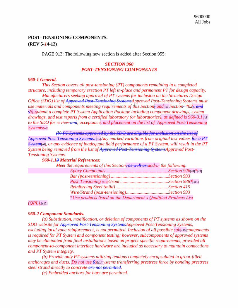
960-1 General.
This Section covers all post-tensioning (PT) components remaining in a completed
structure, including temporary erection PT left in-place and permanent PT for design capacity.
Manufacturers seeking approval of PT systems for inclusion on the Structures Design
Office (SDO) list of Approved Post-Tensioning SystemsApproved Post-Tensioning Systems must
use materials and components meeting requirements of this Section, and [s1]Section 462,. and
sS[s2]ubmit a complete PT System Application Package including component drawings, system
drawings, and test reports from a certified laboratory (or laboratories), as defined is 960-3.1,[s3]
to the SDO for review and, acceptance, and placement on the list of Approved Post-Tensioning
Systems[s4].
(b) PT Systems approved by the SDO are eligible for inclusion on the list of
Approved Post-Tensioning Systems. [s5]Any marked variations from original test values for a PT
System[s6], or any evidence of inadequate field performance of a PT System, will result in the PT
System being removed from the list of Approved Post-Tensioning SystemsApproved Post-
Tensioning Systems.
960-1.13 Material References:
Meet the requirements of this Section, as well as,and[s7] the following:
Epoxy Compounds .....................................................Section 926[s8]*[s9]
Bar (post-tensioning) .................................................Section 933
Post-Tensioning [s10]Grout .........................................Section 938*[s11]
Reinforcing Steel (mild) .............................................Section 415
Wire/Strand (post-tensioning) ....................................Section 933
*Use products listed on the Department’s Qualified Products List
(QPL).[s12]
960-2 Component Standards.
(a) Substitution, modification, or deletion of components of PT systems as shown on the
SDO website for Approved Post-Tensioning SystemsApproved Post-Tensioning Systems,
excluding local zone reinforcement, is not permitted. Inclusion of all possible sub[s13]components
is required for PT System and component testing; however, subcomponents of approved systems
may be eliminated from final installations based on project-specific requirements, provided all
component-to-component interface hardware are included as necessary to maintain connections
and PT System integrity.
(b) Provide only PT systems utilizing tendons completely encapsulated in grout-filled
anchorages and ducts. Do not use Ss[s14]ystems transferring prestress force by bonding prestress
steel strand directly to concrete are not permitted.
(c) Embedded anchors for bars are permitted.
Page 6
9600000
All Jobs
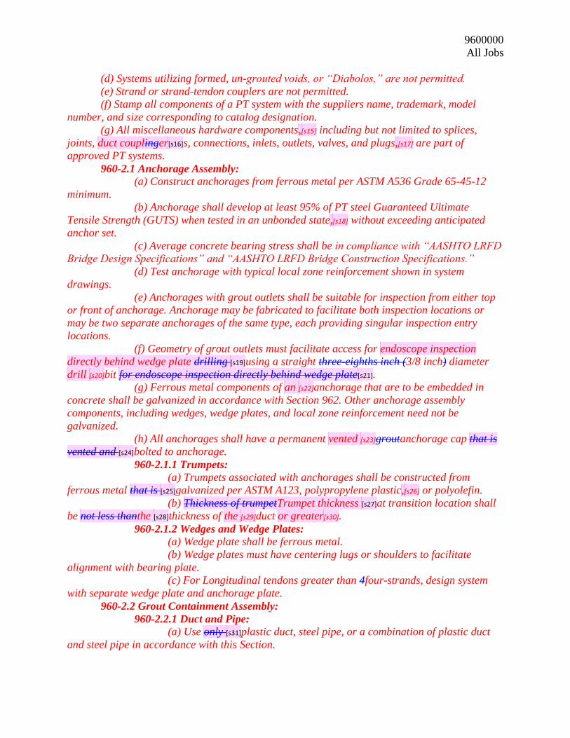
(d) Systems utilizing formed, un-grouted voids, or “Diabolos,” are not permitted.
(e) Strand or strand-tendon couplers are not permitted.
(f) Stamp all components of a PT system with the suppliers name, trademark, model
number, and size corresponding to catalog designation.
(g) All miscellaneous hardware components,[s15] including but not limited to splices,
joints, duct couplinger[s16]s, connections, inlets, outlets, valves, and plugs,[s17] are part of
approved PT systems.
960-2.1 Anchorage Assembly:
(a) Construct anchorages from ferrous metal per ASTM A536 Grade 65-45-12
minimum.
(b) Anchorage shall develop at least 95% of PT steel Guaranteed Ultimate
Tensile Strength (GUTS) when tested in an unbonded state,[s18] without exceeding anticipated
anchor set.
(c) Average concrete bearing stress shall be in compliance with “AASHTO LRFD
Bridge Design Specifications” and “AASHTO LRFD Bridge Construction Specifications.”
(d) Test anchorage with typical local zone reinforcement shown in system
drawings.
(e) Anchorages with grout outlets shall be suitable for inspection from either top
or front of anchorage. Anchorage may be fabricated to facilitate both inspection locations or
may be two separate anchorages of the same type, each providing singular inspection entry
locations.
(f) Geometry of grout outlets must facilitate access for endoscope inspection
directly behind wedge plate drilling [s19]using a straight three-eighths inch (3/8 inch) diameter
drill [s20]bit for endoscope inspection directly behind wedge plate[s21].
(g) Ferrous metal components of an [s22]anchorage that are to be embedded in
concrete shall be galvanized in accordance with Section 962. Other anchorage assembly
components, including wedges, wedge plates, and local zone reinforcement need not be
galvanized.
(h) All anchorages shall have a permanent vented [s23]groutanchorage cap that is
vented and [s24]bolted to anchorage.
960-2.1.1 Trumpets:
(a) Trumpets associated with anchorages shall be constructed from
ferrous metal that is [s25]galvanized per ASTM A123, polypropylene plastic,[s26] or polyolefin.
(b) Thickness of trumpetTrumpet thickness [s27]at transition location shall
be not less thanthe [s28]thickness of the [s29]duct or greater[s30].
960-2.1.2 Wedges and Wedge Plates:
(a) Wedge plate shall be ferrous metal.
(b) Wedge plates must have centering lugs or shoulders to facilitate
alignment with bearing plate.
(c) For Longitudinal tendons greater than 4four-strands, design system
with separate wedge plate and anchorage plate.
960-2.2 Grout Containment Assembly:
960-2.2.1 Duct and Pipe:
(a) Use only [s31]plastic duct, steel pipe, or a combination of plastic duct
and steel pipe in accordance with this Section.
Page 7
9600000
All Jobs
(b) Ducts shall be manufactured by a seamless fabrication method.
Fabricate all duct splices to prevent kinks during all phases of construction.
(c) Do not alter the natural duct color that results from UV protected
polymer.
(d) Corrugated ferrous metal ducts are prohibited.
960-2.2.1.1 Internal Duct (Corrugated Plastic):
(a) PT systems used for tendons internal to concrete shall use
corrugated polypropylene plastic material except where steel pipe is required.
(b) Furnish ducts with minimum wall thickness as follows:
Table 2.2.1.1-1: Corrugated Plastic Duct Minimum Wall Thicknesses
Duct Shape Duct Diameter Duct Thickness
Flat Any Size 0.08 inch
Round 0.9 inch 0.08 inch
Round 2.375 inch 0.08 inch
Round 3.0 inch 0.10 inch
Round 3.35 inch 0.10 inch
Round 4.0 inch 0.12 inch
Round 4.5 inch 0.14 inch
Round 5.125 inch 0.16 inch
Round 5.71 inch 0.16 inch
960-2.2.1.2 External Duct (Smooth Plastic):
(a) PT systems for tendons external to concrete shall use smooth
plastic duct.
(b) External PT system duct shall be polyethylene resin material.
(c) Duct shall have a maximum [s32]dimension ratio (DR) of
seventeen (17) or less [s33]as established by either ASTM D3035 or ASTM F714, as
appropriate,[s34] for manufacturing process used.
(d) Smooth duct shall have a minimum pressure rating of one
hundred pounds per square inch (100 psi.
960-2.2.1.3 Steel Pipe:
Where specified in the Contract Documents and in all deviation
blocks, steel pipes shall be schedule 40 and galvanized in accordance with Section 962.
960-2.2.1.4 Minimum Internal Diameter:
(a) For prestressing bars, duct shall have a minimum internal
diameter of at least [s35]one-half inch (1/2 inch) larger than bar outside diameter, measured
across deformations.
(b) For prestressing bars with couplers, duct shall have a
minimum internal diameter of at least [s36]one-half inch (1/2 inch) larger than largest dimension
of the largest enclosed element.
(c) For multi-strand tendons, ducts must have a minimum cross-
sectional area two-and-a-half (2-1/2) times PT steel cross-sectional area.
960-2.2.1.5 Connections, Fittings, and Tolerance:
(a) Corrugated plastic duct connections shall be from polyolefin
material [s37]or polypropylene material.
Page 8
9600000
All Jobs
(b) All duct connections (e.g., splices, joints, couplings, connection
to anchorage) shall be of such dDevices or methods (e.g., mechanical duct couplers, plastic heat
shrink sleeves), that for all duct connections (e.g., splices, joints, couplings, connection to
anchorage), shall produce a [s38]smooth interior alignment with no lips or kinks.
(c) Use of tape is not permitted to join or repair duct, connections,
or for any other purpose.
(d) Heat welding techniques to make splices between sections of
smooth plastic duct or to make connections with electrofusion duct couplers or other mechanical
duct couplers is permitted.
(e) For external tendons, mechanical duct coupler or a circular
sleeve made of Ethylene Propylene Diene Monomer (EPDM) material shall be used to make all
connections between plastic duct and steel pipe.
(f) Use a reducer Wwhen adjacent sections of duct are directly
connected directly to each other, and the outside diameters shall not vary more than plus or
minus eight-hundredths of an inch (± 0.08 inch). Use a reducer when the variation in diameters
exceeds this tolerance.[s39]
(g) All connections must have a minimum pressure rating of one
hundred pounds per square inch (100 psi).Provide all connections with a minimum pressure
rating of 100 psi.[s40]
(h) Provide EPDM sleeves shall havewith [s41]a minimum wall
thickness of three-eighths inch (3/8 inch) and reinforced with a minimum of four ply polyester
reinforcement.
(i) To connect EPDM duct couplers, use a three-eighths inch
(3/8 inch) wide stainless steel [s42]power seated band and clamps constructed from stainless steel
[s43]on each end of the [s44]EPDM duct couplers and circular sleeves. Band capacity at
installation must withstand one hundred and twenty pounds (120 lbs) seating force.
960-2.2.1.6 Segmental Duct Couplers:
(a) Include segmental duct couplers at joints of permanent internal
PT systems.
(b) Mechanical internal duct couplers shall be stainless steel,
plastic, or a combination of these materials.
(c) Plastic duct couplers shall be polyolefin material [s45]or
polypropylene material.
(d) Metallic components must be stainless steel per
960-2.4.3960-2.4.3.
(e) Segmental duct couplers shall mount perpendicular to the
[s46]bulkhead at segment joints.
(f) Segmental duct couplers shall have the abilitybe able [s47]to
receive duct at an angle of six degrees (6 degree) deviation from perpendicular.
(g) Segmental duct couplers must be able to accommodate angular
deviation of duct without tendon strands touching duct or coupler on either side of segment joint.
(h) Ducts for prestressing,[s48] used exclusively for temporary
erection PT that is to be removed from structure,[s49] are not required to be coupled across
segment joints.
960-2.2.1.7 “O”-Rings:
Page 9
9600000
All Jobs
(a) “O”-ring duct coupler assemblies and segment seal mounting
assemblies shall be polyolefin materials or polypropylene material.
(b) Standard “O”-ring material, for diameters less than or equal
to one-quarter inch (≤ 0.25 inch), shall conform to the requirements of the following table:
Table 2.2.1.7-1 "O"-Ring Material Properties (diameter ≤ 0.25 in)
Mechanical Properties
Shore hardness, ASTM D2240 50-75
Ultimate elongation %, ASTM D412 250% Min.
Tensile strength, ASTM D412 1400 psi Min.
Accelerated Testing
Thermal Deterioration 70 hours @ 257° F, ASTM D573
Change in tensile strength ± 30%
Change of elongation -50%
Change of hardness ± 15 points
Compression Set Method B 22 hours @ 257° F,
ASTM D395 50%
Volume change due to absorption of H2O,
Method D, for 70 hours @ 212°F, ASTM D 471
+ 10%
Environmental Resistance
Ozone Resistance Exposure Method B,
ASTM D1171 Pass
Low Temp. Non-brittle after 3 Min. @ -40°F,
ASTM D2137 Pass
(c) Segment seal assemblies for large diameter [s50]compression
seals, with[s51] diameters greater than one-quarter inch (> 0.25 inch), used to couple ducts at
segment joints, shall conform withto [s52]the requirements in Table 2.2.1.7-1Table 2.2.1.7-1 with
the additions and modifications in the following table:
Table 2.2.1.7-2 Large Diameter Compression Seals (diameter > 0.25 in)
Mechanical Properties
Shore hardness, ASTM D2240 30-60
Tensile strength, ASTM D412 600 psi Min.
Compression Set Method B 22 hours @ 257° F,
ASTM D395 60%
(d) Compression Force - Maximum force to compress “O”-ring to
its final compressed position shall not be greater than twenty-five pounds per square inch
(25 psi) times the area encircled by “O”-ring.
(e) Voided Area - Seal must accommodate material flow within its
own cross sectional area by using a hollow or voided design.
(f) Mounting Assemblies - Assemblies holding “O”-ring must
mount to form bulkhead and provide for duct alignment.
960-2.2.1.8 Heat Shrink Sleeves:
Page 10
9600000
All Jobs
(a) Heat shrink sleeves shall have unidirectional circumferential
recovery and be sized specifically for duct size being coupled.
(b) Use irradiated and cross linked high density polyethylene
backing for external applications and linear-density polyethylene for internal applications.
(c) Use Aadhesives havingwith the same bond value to steel and
polyolefin plastic materials shall be specified[s53].
(d) Heat shrink sleeves shall have an adhesive layer that meets the
requirements of the following table:
Table 2.2.1.8-1 Heat Shrink Sleeve Adhesive Layer Minimum Requirements
Property Test Method Minimum Requirements
Internal Application External Application
Minimum Fully
Recovered Thickness 92 to 126 mils 111 mils
Peel Strength ASTM D 1000 29 pli 46 pli
Softening Point ASTM E 28 162oF 216ºF
Lap Shear DIN 30 672M 87 psi 58 psi
Tensile Strength ASTM D 638 2,900 to 3,480 psi 3,480 psi
Hardness ASTM D 2240 46 to 48 Shore D 52 Shore D
Water Absorption ASTM D 570 Less than 0.05% Less than 0.05%
Color Yellow or Black Black
Minimum Recovery Heat Recovery Test 33% to 58% 23%
Operating Temperature 125°F 150°F
(ef) Install Hheat shrink sleeves shall be installed using procedures
and methods in accordance withspecified in the[s54] manufacturer’s instructions.
960-2.2.2 Attachments:
960-2.2.2.1 Anchorage Caps: (a) Provide permanent groutanchorage caps made of stainless
steel, nylon, polyester, or Acrylonitrile Butadiene Styrene (ABS).
(b) Seal CAnchorage cap shall seal [s55]with “O”-ring seals or
precision fitted flat gaskets placed against the [s56]bearing plate.
(c) Place a grout vent suitable for grout venting and inspection of
the content inside the anchorage cap from either the top or front of the groutanchorage cap as
appropriate (e.g. anchorage caps not accessible after grouting must have a vent at the top of the
cap). GroutAnchorage caps may be fabricated to facilitate both inspection locations or may be
two separate caps of the same type each providing singular inspection entry locations.
(d) AnchorageGrout caps shall have a minimum pressure rating of
one hundred and fifty pounds per square inch (150 psi).
(e) Stainless steel bolts shall be used to attach cap to anchorage.
(f) Certified test reports documenting steel chemical analysis shall
be provided when stainless steel anchorage caps are used.
960-2.2.2.2 Inlets, Outlets, Valves, and Plugs: (a) Provide Ppermanent grout inlets, outlets, valves, and threaded
plugs shall be [s57]made of nylon, polyolefin materials, or stainless steel.
Page 11
9600000
All Jobs
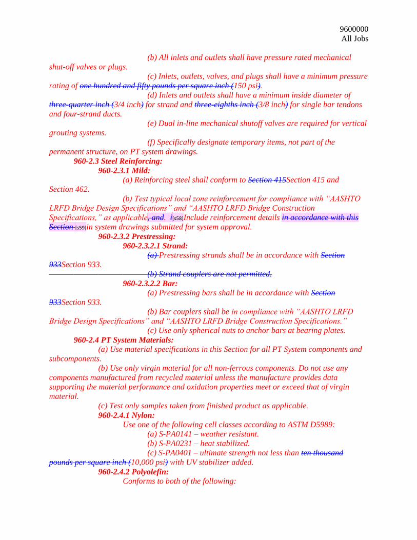
(b) All inlets and outlets shall have pressure rated mechanical
shut-off valves or plugs.
(c) Inlets, outlets, valves, and plugs shall have a minimum pressure
rating of one hundred and fifty pounds per square inch (150 psi).
(d) Inlets and outlets shall have a minimum inside diameter of
three-quarter inch (3/4 inch) for strand and three-eighths inch (3/8 inch) for single bar tendons
and four-strand ducts.
(e) Dual in-line mechanical shutoff valves are required for vertical
grouting systems.
(f) Specifically designate temporary items, not part of the
permanent structure, on PT system drawings.
960-2.3 Steel Reinforcing:
960-2.3.1 Mild: (a) Reinforcing steel shall conform to Section 415Section 415 and
Section 462.
(b) Test typical local zone reinforcement for compliance with “AASHTO
LRFD Bridge Design Specifications” and “AASHTO LRFD Bridge Construction
Specifications,” as applicable, and. i[s58]Include reinforcement details in accordance with this
Section [s59]in system drawings submitted for system approval.
960-2.3.2 Prestressing:
960-2.3.2.1 Strand: (a) Prestressing strands shall be in accordance with Section
933Section 933.
(b) Strand couplers are not permitted.
960-2.3.2.2 Bar: (a) Prestressing bars shall be in accordance with Section
933Section 933.
(b) Bar couplers shall be in compliance with “AASHTO LRFD
Bridge Design Specifications” and “AASHTO LRFD Bridge Construction Specifications.”
(c) Use only spherical nuts to anchor bars at bearing plates.
960-2.4 PT System Materials: (a) Use material specifications in this Section for all PT System components and
subcomponents.
(b) Use only virgin material for all non-ferrous components. Do not use any
components manufactured from recycled material unless the manufacture provides data
supporting the material performance and oxidation properties meet or exceed that of virgin
material.
(c) Test only samples taken from finished product as applicable.
960-2.4.1 Nylon: Use one of the following cell classes according to ASTM D5989:
(a) S-PA0141 – weather resistant.
(b) S-PA0231 – heat stabilized.
(c) S-PA0401 – ultimate strength not less than ten thousand
pounds per square inch (10,000 psi) with UV stabilizer added.
960-2.4.2 Polyolefin: Conforms to both of the following:
Page 12
9600000
All Jobs
(a) Contains antioxidant(s) with a minimum Oxidation Induction
Time (OIT) according to ASTM D3895 of not less than 20 minutes.
(b) Remolded finished material has a minimum failure time of
three (3) hours when tested for stress crack resistance using ASTM F2136 at an applied stress
of three hundred and forty-eight pounds per square inch (348 psi).
960-2.4.3 Stainless Steel: Conforms to the following:
(a) ASTM A240 Type 316 - for metallic components other than
bolts.
(b) ASTM A193 Grade B8M Type 316 - for bolts.
960-2.4.5 Polypropylene: Conforms to all of the following:
(a) Non-colored, unfilled polypropylene according to ASTM
D4101 with a cell class range of PP0340B44541 to PP0340B67884.
(b) Contains antioxidant(s) with a minimum Oxidation Induction
Time (OIT) according to ASTM D3895 of not less than 20 minutes.
(c) Contains a non-yellowing light stabilizer.
960-2.4.6 Polyethylene Resin: Conforms to all of the following:
(a) Meets requirements of ASTM D3350 with a minimum cell class
of 344464C.
(b) Contains antioxidant(s) with a minimum Oxidation Induction
Time (OIT) according to ASTM D3895 of 40 minutes.
960-2.4.7 Ethylene Propylene Diene Monomer (EPDM): Meets requirements of ASTM D1171 using Ozone Chamber Exposure
Method B (no cracks permitted under 2X magnification).
960-3 System Pre-Approval Requirements.
960-3.1 Independent Testing: (a) Use independent laboratories meeting the credentials described in this Section
to perform all testing and to provide certified test reports for material(s) and component(s).
(b) Certification may be performed by a qualified independent laboratory outside
of the United States, only if the facility is pre-approved by the State Materials Office.
(c) Conform all testing procedures used for materials or components to
applicable American Society of Testing and Materials (ASTM) and International Federation of
Structural Concrete (fibp) specifications or as modified in this Section.
960-3.1.1 Material Testing LabLaboratory[s60]: Test plastic components in a certified independent laboratory accredited
through the laboratory accreditation program of the Geosynthetic Accreditation Institute (GAI)
or the American Association for Laboratory Accreditation (A2LA).
960-3.1.2 Component and System Testing LabLaboratory[s61]: Test individual components and the PT system as a whole witnessed by
and/or in a certified independent laboratory audited by AASHTO Materials Reference
Laboratory (AMRL).
960-3.2 Testing Requirements:
960-3.2.1 System Pressure Test:
Page 13
9600000
All Jobs
(a) For each Family of PT Systems, assemble system as detailed on the
System Drawings and perform pressure tests defined in this Article. A Family of PT Systems is a
group of PT tendon/bar assemblies of various sizes using common anchorage devices and
design.
(b) Perform tests on twothe largest [s62]assembliesy and the smallest
assembly (i.e., largest and smallest)[s63] for each family of PT systems.
(c) Include in system test at least one of each component required to
makeinstall [s64]a tendon from groutanchorage cap to groutanchorage cap.
(d) Include plastic duct to steel pipe connections and segment duct
couplers, if applicable.
960-3.2.1.1 Grout Containment Assembly Pressure Test: (a) Assemble anchorage and groutanchorage cap with all required
grouting attachments (e.g., grout tube, valves, plugs, etc.).
(b) Seal opening in anchorage where duct connects.
(c) Condition assembly by maintaining a pressure of one hundred
and fifty pounds per square inch (150 psi) in system for three hours (3 hrs).
(d) After conditioning, assembly must sustain one hundred and fifty
pounds per square inch (150 psi) internal pressure for five minutes (5 min) with no more than
fifteen pounds per square inch (15 psi), or ten percent (10%), reduction in pressure.
(e) Grout Containment Assembly Pressure Test requirement will be
considered satisfied for systems using same anchorages, groutanchorage caps, and grouting
attachments as a previously approved system as long as appropriate documentation from the
previous submittal and written certification is provided by system Supplier stating that identical
components are used in both assemblies.
960-3.2.1.2 External (Smooth) Duct Systems: System testing for external (smooth) duct assemblies requires two
additional tests beyond the Grout Containment Assembly Pressure Test requirements:
(a) Anchorage and its connection to duct/pipe assembly must be
tested in accordance with and satisfy requirements for thethe Internal (Corrugated) Duct
Systems, where duct/pipe assembly consists of all components internal to concrete. Test assembly
at one and five tenths pounds per square inch (1.5 psi).
(b) Duct/pipe assembly consisting of all external duct connections
(e.g., welded duct splices, duct-to-pipe connections, etc.) and grout vent must meet the following:
(1) Use 15 feet of pipe length for test pipe assembly.
(12) Condition assembly by maintaining a pressure of one
hundred and fifty pounds per square inch (150 psi) in system for three hours (3 hrs).
(23) After conditioning, assembly must sustain one hundred
and fifty pounds per square inch (150 psi) internal pressure for five minutes (5 min) with no
more than fifteen pounds per square inch (15 psi), or ten percent (10%), reduction in pressure.
(3) Use fifteen feet (15 feet) of pipe length for test pipe
assembly.[s65]
960-3.2.1.3 Internal (Corrugated) Duct Systems: (a) Perform system test of assembly for compliance with
requirements of Chapter 4, Article 4.2, Stage 1 and Stage 2 Testing contained in fibp
[s66]Technical Report, Bulletin 7 titled, “Corrugated Plastic Duct for Internal Bonded Post-
Tensioning”.
Page 14
9600000
All Jobs
(b) For bar systems, modify system test length to fifteen feet
(15 feet).
(c) For systems being tested for use in precast segmental
construction, modify this test to include one duct coupler or “O”-ring assembly intended for use
at segment joint:
(1) Test duct coupler for proper function by casting it into a
two part concrete test block using match cast techniques. Use blocks that are at least twelve
inches (12 inches) x twelve inches (12 inches) x twelve inches (12 inches).
(2) After concrete has hardened, pull blocks apart and
clean surface of any bond breaker materials.
(3) Using an external apparatus, clamp blocks together and
maintain forty pounds per square inch (40 psi) pressure on block cross-section during pressure
test. Do not apply epoxy compound [s67]between blocks for this portion of test.
(4) Pressurize duct within test block to five pounds per
square inch (5 psi) and lock off outside air source.
(5) Assembly must sustain a five pounds per square inch
(5 psi) internal pressure for five minutes (5 min) with no more than a five-tenths pounds per
square inch (0.5 psi), or ten percent (10%), reduction in pressure.
(d) Remove clamping device, separate duct coupler blocks from
duct system, and place a one-sixteenth inch (1/16 inch) layer of epoxy compound [s68](Type B per
Section 926) on face of both blocks, clamp blocks together, and maintain a pressure of forty
pounds per square inch (40 psi) on block cross-section for twenty-four hours (24 hrs). Upon
removal of clamping force, demolish blocks. Duct coupler and attached ducts should be intact
and free of epoxy compound [s69]and properly attached without crushing, tearing, or other signs
of failure.
960-3.2.2 Minimum Bending Radius: Establish bending radius for duct through testing. Test consists of a
modified duct wear test as described in Chapter 4, Article 4.1.7 of FIBfip[s70] Technical Report,
Bulletin 7 titled, “Corrugated Plastic Duct for Internal Bonded Post-Tensioning”. Use identical
test apparatus as that used for wear test with same clamping force as a function of number of
strands in a duct.
(a) Modify procedure as follows: After the specimen has reached
its final position, remove the specimen and confirm that the residual thickness is adequate. With
confirmation that the residual thickness is acceptable, immediately (within 30 minutes) reapply
the original clamping force for fourteen (14) days.
(b) Upon completion of test, remove duct and measure wall
thickness along strand path. Wall thickness must not be less than three hundredths inch (≥
0.03 inch) for duct up to three and thirty-five hundredths inches (≤ 3.35 inch) diameter and not
less than four hundredths inch (≥ 0.04 inch) for duct greater than three and thirty-five
hundredths inches (> 3.35 inch) diameter.
960-3.2.3 Additional Material Tests: Ensure internal duct system components and accessories meet
requirements of Chapter 4, Articles 4.1.1 through 4.1.8 of International Federation of Structural
Concrete (fibp[s71]) Technical Report, Bulletin 7 titled, “Corrugated Plastic Duct for Internal
Bonded Post-Tensioning” as modified below:
Page 15
9600000
All Jobs
(a) Conduct lateral load resistance test (fibp[s72] 4.1.4) without use
of a duct stiffener plate using a one hundred and fifty pound (150 lb) load for all sizes.
(b) Wear resistance of duct (fibp[s73] 4.1.7) as modified above.
(c) Bond length test (FIBfip [s74]4.1.8) must achieve 40% of GUTS
in a maximum length of 16 duct diameters.
960-3.3 Required Sizes: Develop and test PT systems for both internal (corrugated duct) and external
(smooth duct) applications for the following:
(a) Department standard tendon sizes for designing and detailing consist
of six-tenth inch (0.6 inch) diameter strand in anchorages containing four4, seven7, twelve12,
fifteen15, nineteen19, twenty-seven27, and thirty-one31 strands.
(b) Standard bar sizes consistrange[s75] from five-eighths inch (5/8 inch) to
two-and-a-half inch (2-1/2 inch) diameter.
(c) Systems using alternate anchorage sizes and/or strands utilizing one-
half inch (1/2 inch) strand and providing equivalent force to these standard sizes may be
submitted for approval.
960-3.4 System Modifications: (a) Contact the SDO for direction before attempting to change pre-approved PT
system materials or components.
(b) Repeat all appropriate material, component, and entire system tests if any
component of a pre-approved PT system is modified or replaced, excluding local zone
reinforcement.
(c) Submit an updated application to the SDO containing test reports and revised
system drawings for proposed modified systems.
960-3.5 Component Samples:
At no cost to the Department, furnish all required material samples to laboratory
for testing and to the Department as requested.
960-3.6 Calculations, Drawings, and Certification: (a) Show fully detailed drawings of all component configurations, connections,
anchorages, inlets, outlets, high point outlet inspection details, anchorage inspection details,
permanent groutanchorage caps and application limits of the PT system for approval and
posting on the SDO’s website for Approved Post-Tensioning SystemsApproved Post-Tensioning
Systems.
(b) Submit details of typical local zone reinforcement in system drawings signed
and sealed by a Specialty Engineer.
(c) Indicate that all PT system components are stamped with (1) Manufacturer’s
name, (2) trademark model number, and (3) size corresponding to catalog description on PT
System drawings.
(d) Provide an application package cover letter signed by an officer of the PT
System Vendor certifying that the submitted PT system,[s76] as a whole and all of its individual
components,[s77] meet or exceed all material and component/system requirements of this Section,
as demonstrated by the submittal.
(1) Indicate in this certification that all testing required by this Section
was performed by an appropriately accredited certified[s78] independent laboratory (or
laboratories), as defined in 960-3.1,[s79] and that all tests were performed to applicable American
Page 16
9600000
All Jobs
Society of Testing and Materials (ASTM) and International Federation of Structural Concrete
(FIBfip[s80]) specifications.
(2) Provide proof of current laboratory accreditation specifically
indicating applicable accreditation categories related to PT Systems.
(e) Provide Ensure [s81]all material and component certifications required
throughout this Section are provided[s82].